Table of Contents
Advertisement
Available languages
Available languages
Quick Links
Advertisement
Table of Contents

Subscribe to Our Youtube Channel
Related Manuals for Schuller ASPAS 316545


Summary of Contents for Schuller ASPAS 316545
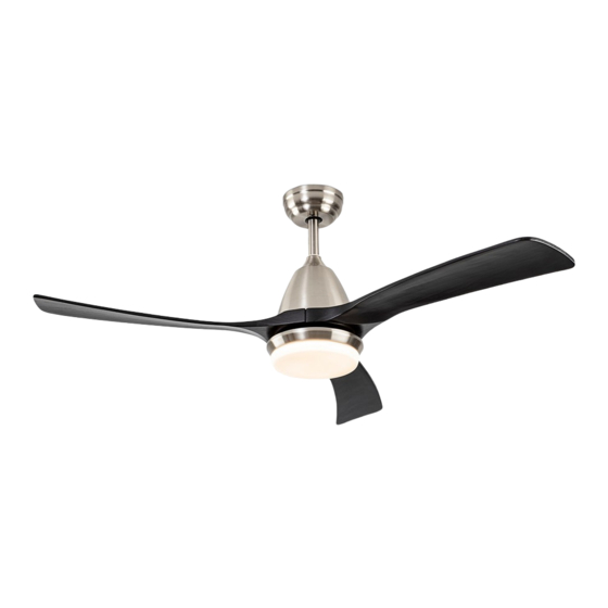
- Page 1 ASPAS VENTILADOR DE TECHO 316545 GUÍA DE INSTALACIÓN Rev.03.21...
-
Page 2: Recomendaciones De Seguridad
LISTADO DE COMPONENTES INCLUIDOS. Abra con cuidado el embalaje. Retire los elementos de las inserciones de espuma de poliestireno. Retire la carcasa del motor y colóquela sobre una alfombra o espuma de poliestireno para evitar dañar el acabado. Nota: Verifique con el inventario de piezas que se hayan incluido todas las piezas antes de iniciar la instalación. -
Page 3: Guia De Instalación
Para reducir el riesgo de incendio, descarga eléctrica o daño al motor, no use reguladores de velocidad de pared con este ventilador. Use solo el control de velocidad del mando a distancia. NOTA: Las precauciones e instrucciones de seguridad importantes que aparecen en el manual no están destinadas a cubrir todas las condiciones posibles, y situaciones que pueden ocurrir. - Page 4 INSTALACIÓN EN TECHO DE CEMENTO Montaje de los componentes del ventilador: 1- Selección de la altura del ventilador: Dispone de dos tubos de instalación ( corto 15 cm y largo 25 cm). Recibirá el tubo corto ya premontado junto al anclaje antibalanceo. Esto proporciona una altura total de 45 cm al ventilador una vez montado. Si desea una altura mayor (55 cm ) deberá...
- Page 5 3- Montaje a techo. -Retirar los 4 tornillos del Anclaje anti-balanceo - Colgar el conjunto en el Soporte a techo, insertando el Anclaje anti-balanceo en la posición indicada en el esquema. Volver a fijar los tornillos para inmovilizar el conjunto. 4- Conexión a corriente.
- Page 6 -Una vez conectado, subir el canopí hasta el techo cubriendo el anclaje, módulo y cableado. Bloquear con los tornillos. 5- Montaje de las palas Instalar las palas, mediante los tornillos proporcionados.
- Page 7 6- Montaje de la placa iluminación. Montar el plafón metálico fijándolo bajo las aspas. -Conectar la Placa LED a los cables que salen de la cara inferior del motor, mediante la ficha de conexión rápida. Después fijar la placa LED, mediante sus imanes, en el plafón metálico. 7- Colocar el difusor de cristal.
-
Page 8: Manual De Uso
Función INVERTER ( INVIERNO / VERANO) cambio de sentido de giro. TEMPORIZADOR: 1 hora / 2 horas / 4 horas / 8 horas. SCHULLER RECOMIENDA LA COLOCACIÓN DE PROTECTORES DE SOBRETENSIÓN PARA EVITAR LOS DAÑOS EN LOS COMPONENTES ELECTRÓNICOS DE LA LUMINARIA LED.Disponibles en nuestro catálogo. -
Page 9: Ceiling Fan
ASPAS CEILING FAN 316545 INSTALLATION GUIDE Rev.03.21... -
Page 10: Safety Recommendations
LIST OF INCLUDED COMPONENTS. Carefully open the packaging. Remove the elements from the Styrofoam inserts. Remove the motor housing and place it on a carpet or on some Styrofoam to avoid damaging the finish. Note: Check the parts inventory to ensure that all parts have been included before commencing installation. SAFETY RECOMMENDATIONS. - Page 11 • To reduce the risk of a fire, electric shock, or motor damage, do not use wall speed regulators with this fan. Only use the speed regulator on the remote control. • NOTE: The important safety instructions and precautions included in the manual are not intended to cover all possible circumstances or situations.
- Page 12 INSTALLATION ON A CEMENT CEILING Mounting the fan components: 1- Choosing the fan height: Two downrods are included (short 15 cm and long 25 cm). The short downrod will already be pre- assembled to the anti-wobble bracket. This gives a total height of 45 cm to the fan once mounted. If you want the fan to hang lower (55 cm), you must replace the short downrod with the long one.
- Page 13 3- Ceiling mounting. -Remove the 4 screws from the Anti-wobble bracket - Hang the assembly on the ceiling mounting bracket, inserting the anti-wobblebracket in the position indicated in the diagram. Secure the screws to fix the assembly firmly in place. 4- Connecting to the power supply -Insert the control module into its allocated slot in the anti-wobble bracket (as per the diagram) and connect the cables from the fan body following the colour guide and numbers indicated on the module.
- Page 14 -Once connected, raise the canopy until it is in place and covering the bracket, module and wiring. Fix in place using the screws provided. 5- Assembling the blades Install the blades, using the screws provided.
- Page 15 6- Fitting the ceiling light. Fit the metal light ring by fixing it in place under the blades -Connect the LED Board to the cables from the lower end of the motor, using the quick splice connector. Then fix the LED board in place onto the metal ring, by means of the magnets. 7- Fitting the glass shade .
- Page 16 • INVERTER function (WINTER / SUMMER) change of direction of rotation. TIMER: 1 hour / 2 hours / 4 hours / 8 hours. SCHULLER RECOMMENDS TO PLACE SURGE PROTECTORS TO AVOID DAMAGES TO THE ELECTRONIC COMPONENTS OF THE LED LUMINAIRE. Available in our catalogue If you have any technical questions, please do not hesitate to contact our technical Department.
Need help?
Do you have a question about the ASPAS 316545 and is the answer not in the manual?
Questions and answers