Advertisement
Quick Links
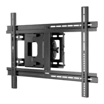
ALF109
(6904-002009<00>)
Wood
13mm
5.5mm
.)
(1/2 in.)
(7/32 in
Sanus Systems
2221 Hwy 36 West
Saint Paul, MN 55113 USA
Customer Service
Americas: 800-359-5520 • 651-484-7988 • info@sanus.com
Europe, Middle East, and Africa: + 31 40 2324700 • europe.sanus@milestone.com
Asia Pacifi c: 86 755 8996 9226 • sanus.ap@milestone.com
accents.sanus.com
©2010 Milestone AV Technologies, a Duchossois Group Company.
All rights reserved. Accents is a Milestone brand.
All other brand names or marks are used for identifi cation purposes and are trademarks of their respective owners.
Advertisement

Related Manuals for Sanus ALF109


Summary of Contents for Sanus ALF109
- Page 1 Saint Paul, MN 55113 USA Customer Service Americas: 800-359-5520 • 651-484-7988 • info@sanus.com Europe, Middle East, and Africa: + 31 40 2324700 • europe.sanus@milestone.com Asia Pacifi c: 86 755 8996 9226 • sanus.ap@milestone.com accents.sanus.com ©2010 Milestone AV Technologies, a Duchossois Group Company.
- Page 2 CAUTION: IMPORTANT SAFETY INSTRUCTIONS – SAVE THESE INSTRUCTIONS – PLEASE READ ENTIRE MANUAL BEFORE USING THIS PRODUCT Specifi cations Weight capacity-DO NOT EXCEED: 58.9 kg (130 lbs) includes TV and any accessories Tilt: +11° / -10° CAUTION: Avoid potential personal injuries and property damage! ...
- Page 3 10° 11° 10° 11° 72.7 mm 2.86 in. 225.1 mm 8.86 in. 100mm to 710mm 431.8 mm 17.0 in. 223.5 mm 165.1 mm 500 mm 475 mm 8.8 in. 6.5 in. 19.7 in. 18.7 in. 472.4 mm 18.6 in. 775 mm 30.5 in.
- Page 4 Supplied Parts and Hardware Before starting assembly, verify all parts are included and undamaged. If any parts are missing or damaged, do not return the damaged item to your dealer; contact Sanus Systems Customer Service. Never use damaged parts! Hardware and procedures for multiple mounting confi gurations are included. When you see this symbol , choose the correct confi guration to suit your needs.
- Page 5 M4 x 12mm M4 x 30mm [07] x 4 [08] x 4 [09] x 4 M5 x 12mm M5 x 30mm [10] x 4 [11] x 4 [12] x 4 M6 x 20mm M6 x 12mm M6 x 35mm [13] x 4 [14] x 4 [15] x 4 [16] x 4...
- Page 6 CAUTION: Install TV Brackets Before you begin, hand thread screws into the threaded inserts on the back of your TV to determine the correct screw diameter (M4, M6, or M8). Verify that there are adequate threads to secure the brackets to the monitor. If you encounter resistance, stop immediately and contact customer service. CAUTION: Avoid potential personal injuries and property damage! Use the shortest screw and spacer combination to accommodate your needs.
- Page 7 For TVs with a fl at/unobstructed back. Ensure that the [05] brackets are level and equally spaced top and bottom on the back of the TV. Standard confi gurations are shown. If you need extra space to accommodate cables, recesses, or protrusions, see installation option 1-2 that uses spacers.
- Page 8 For TVs with an irregular/obstructed back. Ensure that [06] the brackets are level and equally spaced top and bot- tom on the back of the TV. Standard confi gurations are shown. For special applications, or if you are uncertain about your hardware selection, contact Customer Service.
- Page 9 Slide the horizontal brackets [03] and [04] onto the vertical brackets [05] and [06]. Make sure that they are evenly spaced left to right. Install screws [27] to lock horizontal brackets [03] and [04] in position. [03] [06] [05] [04] [03] [27] 6904-002009 <00>...
- Page 10 CAUTION: Wall Mounting 2-1: Wood Stud Mounting CAUTION: Improper use could reduce the holding power of the lag bolt. To avoid potential injuries or property damage: Pilot holes MUST be drilled to a depth of 75 mm (3 in.), using a 5.5 mm (7/32 in.) diameter drill bit. ...
- Page 11 13mm 5.5mm (1/2 in.) (7/32 in. Wood Stud Wall Mounting – See Cautions in Step 2. Locate studs. Verify the center of the stud with an awl or thin nail or use an edge to edge stud fi nder. Level the wall plate [01] and mark the hole locations. <...
- Page 12 CAUTION: HANG THE SWING ARM [02] ONTO THE WALL PLATE [01] Install the saftey bolts [30] using the 3/16 in. hex key [25]. CAUTION: Avoid potential injuries or property damage! Ensure the safety bolts [30] are secure. Periodic tightening may be required. [02] [01] [30]...
- Page 13 CAUTION: HANG THE TV/BRACKET ASSEMBLY ONTO THE SWING ARM HEAVY! You will need assistance with this step. Level the TV/bracket assembly and install the retaining screw [26]. CAUTION: Avoid potential injuries or property damage! Be sure to install the retaining screw [26] securely.
-
Page 14: Cable Management
CABLE MANAGEMENT NOTE: Be sure to leave enough slack in the cables to allow the monitor to move freely. Use the cable ties [33] and cable tie holders [32] to secure the cables to the arm [02]. [02] [33] [32] 6904-002009 <00>... -
Page 15: Tension Adjustment
MAINTENANCE: TENSION ADJUSTMENT NOTE: [A] Adjust arm extension and swivel tension. [B] Adjust up/down tilt tension. [31] [25] 6904-002009 <00>... - Page 16 Milestone AV Technologies and its affi liated corporations and subsidiaries (collectively, “Milestone”), intend to make this manual accurate and complete. However, Milestone makes no claim that the information contained herein covers all details, conditions, or variations. Nor does it provide for every possible contingency in connection with the installation or use of this product.
Need help?
Do you have a question about the ALF109 and is the answer not in the manual?
Questions and answers