Viessmann MatriX Service Instructions Manual
Hide thumbs
Also See for MatriX:
- Service instructions manual (52 pages) ,
- Service instructions for contractors (52 pages) ,
- Service instructions for contractors (44 pages)
Table of Contents
Advertisement
Quick Links
Advertisement
Table of Contents

Related Manuals for Viessmann MatriX


Summary of Contents for Viessmann MatriX
- Page 1 VIESMANN Service instructions for contractors MatriX radiant burner Type VMIII Pressure-jet gas burner for the Vitocrossal 300, type CM3 Rated output 80 to 130 (87 to 142) kW For applicability, see the last page MatriX radiant burner Please keep safe.
- Page 2 Safety instructions Safety instructions Please follow these safety instructions closely to prevent accidents and mate- rial losses. Safety instructions explained ■ all current safety regulations as defined by DIN, EN, DVGW, TRGI, Danger TRF, VDE and all locally applicable This symbol warns against the standards, risk of injury.
- Page 3 ■ When using gas as fuel, also close the For replacements, use only orig- main gas shut-off valve and safeguard inal spare parts from Viessmann against unauthorised reopening. or those which are approved by ■ Isolate the system from the power sup- Viessmann.
-
Page 4: Table Of Contents
Index Index Commissioning, inspection, maintenance Steps – commissioning, inspection and maintenance.......... Further details regarding the individual steps............Air pressure switch.................... 21 Burner control unit Burner control unit MPA 51.................. 22 Troubleshooting Diagnosis......................29 Burner control unit flow chart................35 Burner control unit connection diagram............37 Component overview.................. -
Page 5: Commissioning, Inspection, Maintenance
Commissioning, inspection, maintenance Steps – commissioning, inspection and maintenance For further information regarding the individual steps, see the page indicated Commissioning steps Inspection steps Maintenance steps Page • • • 1. Commissioning the system........... • 2. Checking the gas type............ •... -
Page 6: Further Details Regarding The Individual Steps
Commissioning, inspection, maintenance Further details regarding the individual steps Commissioning the system Danger Note CO formation as a result of an An examination of the burner setting with incorrect burner setting can have the boiler heated up (min. 40 ºC) is serious health implications. -
Page 7: Checking The Gas Type
Commissioning, inspection, maintenance Further details regarding the individual steps (cont.) Checking the gas type 1. Determine the gas type and Wobbe 2. In the delivered condition, the burner index (Wo) from your gas supply util- is set up for natural gas E. If required, ity. -
Page 8: Checking The Static And The Supply Pressure
Commissioning, inspection, maintenance Further details regarding the individual steps (cont.) 08. Refit the gas pipe. Insert gaskets into fittings A and C. Danger Escaping gas leads to a risk of explosion. Check all fittings for gas tightness. 09. Secure the gas train cables to the gas pipe. - Page 9 Commissioning, inspection, maintenance Further details regarding the individual steps (cont.) Supply pressure 1. Start the burner. Note For commissioning, see page 6. Switch the burner to maximum out- put. To do so, activate the emissions test switch on the control unit. 2.
-
Page 10: Checking The Nozzle Pressure
Commissioning, inspection, maintenance Further details regarding the individual steps (cont.) Checking the nozzle pressure Preparing the test 1. Undo the screw inside test nipple A, but do not remove. 2. Connect the pressure tester at test nipple A. 3. Open the gas shut-off valve. 4. - Page 11 Commissioning, inspection, maintenance Further details regarding the individual steps (cont.) Note 5. Press "S" D and "-" C simultane- During the adjustment, also check ously. The burner is now in operating the gas throughput by means of a mode. volumetric test. 6.
-
Page 12: Checking The Co 2 Content
Commissioning, inspection, maintenance Further details regarding the individual steps (cont.) Note The gas pressure must not be altered The nozzle pressures apply to 15 ºC, from these values because of the factory 1013 mbar, dry. setting to natural gas E or LL. Checking the CO content Preparing the test... - Page 13 Commissioning, inspection, maintenance Further details regarding the individual steps (cont.) Burner output Permissible CO 4. Record the actual value in the report (on page 45). in kW content in % 9.0 to 9.5 105 to 130 8.7 to 9.2 3. If the CO content has to be adjus- ted: Turn adjusting screw "V"...
-
Page 14: Checking The Ionisation Current
Commissioning, inspection, maintenance Further details regarding the individual steps (cont.) 4. Record the actual value in the report (on page 45). Rechecking the values Ramp up and down to the upper and lower outputs again using the pro- gramming unit in the burner control unit. -
Page 15: Shutting Down The System
Commissioning, inspection, maintenance Further details regarding the individual steps (cont.) 04. Switch OFF the main isolator. 09. Record the actual value in the report (on page 45). Note Test cable no.1 is required when 10. Switch the main isolator OFF, checking with the Testomatik-Gas. -
Page 16: Checking The Burner Gauze Assembly
Commissioning, inspection, maintenance Further details regarding the individual steps (cont.) Checking the burner gauze assembly 1. Remove the gas supply pipe; to do so, release the control cables and plug from the gas train. 2. Undo the screws on the boiler door and open the door. -
Page 17: Checking The Ignition And Ionisation Electrodes
Commissioning, inspection, maintenance Further details regarding the individual steps (cont.) Checking the ignition and ionisation electrodes 1. Check the ignition electrodes and the Ignition electrodes ionisation electrode for the correct gap to the burner gauze assembly, and for damage (replace if required). -
Page 18: Cleaning The Burner
Commissioning, inspection, maintenance Further details regarding the individual steps (cont.) Cleaning the burner 1. Remove the connecting cables from fan B. 2. Remove the fan. 3. Clean the fan casing and impeller. 4. For severe fan contamination (dust, fluff), remove the ignition, ionisation and control cables from the burner door, then remove and clean air col- lector casing A. -
Page 19: Checking Both Gas Train Valves For Tightness
5 min, then the gas train is tight. Otherwise there is a leak. If this is the case, return the gas train to Viessmann Werke for testing. 1. Close the gas shut-off valve. 7. After the test, close both test nipples by tightening the relevant screws. -
Page 20: Final Testing
Commissioning, inspection, maintenance Further details regarding the individual steps (cont.) Final testing 1. Carry out the final tests according to 2. Record the actual values in the report the information on pages 12 to 14. (on page 45). Operating and service documents 1. -
Page 21: Air Pressure Switch
Air pressure switch Air pressure switch Function The signal from air pressure switch A is assessed under the following operating conditions: ■ prior to the fan start (idle state check) ■ in the pre-purge phase ■ in control mode, subject to at least a starting output being produced. -
Page 22: Burner Control Unit
Burner control unit Burner control unit MPA 51 Display and programming unit Function A display and programming unit is integrated into the burner control unit. The display indicates the relevant operating conditions, the service and parameter conditions as well as all fault and error messages. The display comprises three elements of Status Service seven segments each. - Page 23 Burner control unit Burner control unit MPA 51 (cont.) Idle state check Status Service Fan ramp-up Pre-purge Status Service Pre-ignition Status Service Safety time Status Service Flame established Status Service Operation with flame Status Service Post-purge Status Service Standby Status Service...
- Page 24 Burner control unit Burner control unit MPA 51 (cont.) Display Status Service (single digit) (two digits) Operating display in Current operating Display "FL" if a flame Page 23 standard mode state; see pages 22 signal is present and 23 Operating display for Message code "A"...
- Page 25 Burner control unit Burner control unit MPA 51 (cont.) Note If another parameter set is selected, this must be acknowledged (see page 25). Setting Setting Rated burner output Reduced burner output Parameter set 0 Parameter set 5 ≙ 80 (87) kW ≙...
- Page 26 Burner control unit Burner control unit MPA 51 (cont.) Status Service 1. Check the DIP switch setting; if 3. Press the reset button. required, change it in accordance Then the operating display will be with page 24. shown again. 2. Press b and a simultaneously for approx.
- Page 27 Burner control unit Burner control unit MPA 51 (cont.) Status Service A Fault code of the most recent fault 1. Press a. Status Service As long as this key is held down, the operating phase under which the fault occurred is displayed under "Service".
- Page 28 Burner control unit Burner control unit MPA 51 (cont.) 2. Press S to scan the penultimate to Status Service the sixth most recent fault. Display under Fault "Status" Most recent fault Sixth most recent fault The relevant fault code is displayed under "Service".
-
Page 29: Troubleshooting
Troubleshooting Diagnosis Faults with fault indication on the display and programming unit Message codes Message System characteris- Cause Measures code tics Burner not working Gas pressure Check gas pressure switch fault switch Burner not working Lack of gas Notify gas supply utility Burner in fault state See fault code See fault code steps... - Page 30 Troubleshooting Diagnosis (cont.) Fault code System characteris- Cause Measures tics No flame signal after Ionisation elec- Adjust ionisation elec- the safety time; the trode incorrectly trode (see page 17). ionisation flame mon- adjusted itor reports no flame signal No flame signal after Ignition electrodes Adjust ignition electrodes safety time;...
- Page 31 Troubleshooting Diagnosis (cont.) Fault code System characteris- Cause Measures tics Ionisation flame mon- Gas train leaks Replace gas train itor reports external light ingress during start-up or after post- purge Ionisation flame mon- Incorrect parame- Adjust the parameter set itor reports external ter set selected (see page 24 to 25) light ingress during...
- Page 32 Troubleshooting Diagnosis (cont.) Fault code System characteris- Cause Measures tics Burner control unit Error in feedback Replace burner control fault from gas safety unit valves; output relay does not respond Burner control unit Error in feedback Replace burner control fault from easy start unit valve;...
- Page 33 Troubleshooting Diagnosis (cont.) Internal system fault Internal system faults are created if a perfect program sequence can no longer be guaranteed. Fault code System characteris- Cause Measures tics 01 and 02, Fault in burner con- Internal system Replace burner control 04 to 15, trol unit area fault...
- Page 34 Troubleshooting Diagnosis (cont.) Fault Cause Measures Excessive flue gas Excessive gas Adjust gas throughput in accord- temperature throughput ance with rated boiler output. Check condition of boiler secondary heating surfaces; clean if required. Whining noises Incorrect CO set- Adjust burner in accordance with the details on page 12 tings...
-
Page 35: Burner Control Unit Flow Chart
Burner control unit flow chart Burner control unit flow chart... - Page 36 Burner control unit flow chart Burner control unit flow chart (cont.) After the controller issues a heat demand, the following program will run: Phase Duration Test for heat demand Check of the idle state of the air pressure switch and the 1 to 30 s Fan ramps up to speed (if the air pressure switch does 1 to 30 s...
-
Page 37: Burner Control Unit Connection Diagram
Burner control unit connection diagram Burner control unit connection diagram Ignition Speed 6.3 A (slow) A1 Burner control unit MPA 51 F4 Minimum pressure, gas pressure A2 Display unit with reset function switch B1 Flame monitoring via ionisation cur- F6 Air pressure switch rent H1 Hours run meter, total B2 Safety chain jumper... - Page 38 Burner control unit connection diagram Burner control unit connection diagram (cont.) K1 Relay contact T1 Ignition unit M1 Fan motor with PWM control and Y1 Gas fuel safety valve feedback Y2 Easy start valve/air-control-pres- S1 ON/OFF switch (inside control unit) sure (option) S2 Temperature controller S3 Output controller (inside control...
-
Page 39: Component Overview
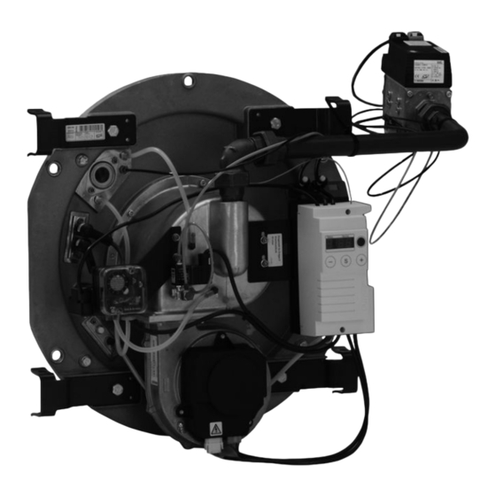
Component overview Component overview A Boiler door G Fan B Sight glass H Display and programming unit C Ignition electrodes K Burner control unit D Air pressure switch L Gas train E Ignition transformer M Gas supply pipe F Ionisation electrode N Air collector casing... - Page 40 Component overview Component overview (cont.) K Burner control unit N Air collector casing L Gas train O Thermal insulation block M Gas supply pipe P Burner gauze assembly...
-
Page 41: Control Unit
Adjusting codes at the control unit Vitotronic service instructions In conjunction with the following control units: ■ Vitotronic 100, type GC1 ■ Vitotronic 200, type GW1 ■ Vitotronic 300, type GW2 Coding address Rated output of the MatriX radiant burner in kW... -
Page 42: Parts List
Parts list Parts list Information for spare parts orders 014 Ionisation cable Quote the type and serial numbers (see 015 Ignition unit connecting cable type plate) and the position number of 016 Fan motor connecting cables the required part (as per this parts list). 018 Gas train connecting cables Obtain standard parts from your local 019 Connecting cable 3/2-way solenoid... - Page 43 Parts list Parts list (cont.) 030 039...
- Page 44 Parts list Parts list (cont.)
-
Page 45: Report
Report Report Setting and test values Commission- Maintenance/ service Static pressure mbar Supply pressure (flow pressure) = for natural gas E mbar = for natural gas LL mbar Tick gas type Nozzle pressure actual mbar adjusted mbar Carbon dioxide content CO ■... -
Page 46: Specification
Specification Specification Rated boiler output = 50/30 °C = 80/60 °C CE designation CE-0085 BL 0403 Burner type VMIII-1 VMIII-2 VMIII-3 Voltage Frequency Power consumption Motor speed 1504-4736 1344-4320 1470-4740 Modulation range 33-100 Dimensions – restrictor and mixing pipe Rated boiler output Gas holes in the mixing pipe a 7 mm 8 x 4.0... -
Page 47: Keyword Index
Keyword index Keyword index Air pressure switch......21 Fault code..........29 Applicability........48 Fault display........26 Fault memory........27 Faults Burner ■ With fault indication......29 ■ Cleaning.........18 ■ Without fault display.......33 ■ Fitting..........18 Final testing........20 Burner control unit Flow chart..........35 ■ Connection diagram.......37 Flow pressure........9 ■... - Page 48 Applicability Serial no.: 7141875 7141876 7141877 Viessmann Werke GmbH&Co KG Viessmann Limited D-35107 Allendorf Hortonwood 30, Telford Telephone: +49 6452 70-0 Shropshire, TF1 7YP, GB Fax: +49 6452 70-2780 Telephone: +44 1952 675000 www.viessmann.com Fax: +44 1952 675040 E-mail: info-uk@viessmann.com...
Need help?
Do you have a question about the MatriX and is the answer not in the manual?
Questions and answers