Table of Contents
Advertisement
Quick Links
Advertisement
Table of Contents

Summary of Contents for abi SENTRY
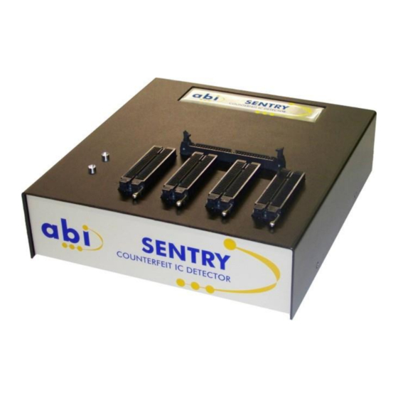
- Page 1 SENTRY Counterfeit IC Detector OPERATOR’S MANUAL ABI Electronics Ltd Dodworth Business Park Barnsley S75 3SP United Kingdom +44 (0)1226 207420 +44 (0)1226 207620 sales@abielectronics.co.uk www.abielectronics.co.uk Copyright © 2012 – 2017 ABI Electronics Ltd...
-
Page 2: Table Of Contents
Editing a package ......................13 e) Viewing a package ......................13 f) Deleting a package ......................14 g) Exporting a package ......................14 h) Importing a package ......................14 Copyright © 2012 - 2017 ABI Electronics Ltd Page 1... - Page 3 Comparison point tolerance ....................25 b) Pin comparison tolerance ....................25 c) Overall result tolerance ..................... 25 d) Results ..........................26 8.7 Reports ............................26 8.8 Keeping your software up to date ..................... 26 Copyright © 2012 - 2017 ABI Electronics Ltd Page 2...
-
Page 4: How To Use This Manual
I- Preface Thank you for purchasing the ABI SENTRY Counterfeit IC Detector. Please refer to this manual before attempting to turn on or operate the equipment. 1.1 How to use this manual This manual is divided into sections describing all aspects of the SENTRY operation. There is a getting started guide (also available from the welcome screen in the software), designed to get you up and working quickly, followed by more detailed instructions on the various operating modes and functions. -
Page 5: Ii- Introduction
IC with data for a suspect IC. The SENTRY contains a blank library of devices which you can expand by adding the devices you need to check. Any electronic device can be added, provided there is a physical means of contacting the device available (for example, an IC socket). Each device can have documents associated with it, such as photos of device markings, data sheets and other documents. -
Page 6: D) Sentry Software Operation
The SENTRY connects to a standard PC via a high speed USB interface. The SENTRY operating software on your PC controls all system operations and functions, and provides full database facilities for storage and reporting of... -
Page 7: Iii- Getting Started
USB driver installation Connect the SENTRY unit to a suitable mains supply and switch on, then connect the unit to a spare high speed USB 2.0 port Found New Hardware – “ABI SENTRY on your PC with the cable supplied. After a few seconds you will see the message “... -
Page 8: Quick Start Guide
Notes field can be used for any purposes. Step 2 : Place the component in the SENTRY unit. By default for DIL packages, this should be on the left ZIF (Zero Insertion Force) socket, at the top (see picture below). -
Page 9: Iv- Library Management
The device text filter. By typing part or all of a component name or manufacturer for a device the SENTRY software will search through your device library and return only devices which match your criteria. This can also be used in conjunction with the device type filter to further refine a search for a specific device. -
Page 10: A) Adding A Device To The Library
Manual Ground Pins reference mode, all pins which are should be indicated here so that SENTRY can accurately scan the device. You have now completed adding a new device. Click to save the device into your library. -
Page 11: F) Importing A Device
USB memory stick to transfer the library. On a separate PC, navigate once again to the SENTRY Data folder and overwrite all the folders with the previously saved data. Note: this action will completely overwrite the database on the PC the data is being transferred to. It is therefore not possible to transfer and merge a library with an existing one using this option. -
Page 12: V- Package Management
V- Package management The SENTRY software is supplied with a comprehensive set of package definition files for the most common packages in use today. However, there will be times when you may wish to design your own. This could be for new devices in unusual packages, discrete devices, or even for entire modules which you may want to check using SENTRY. -
Page 13: A) Adding A New Package
In addition, the mouse wheel (if available) can also be used to zoom in and out. Copyright © 2012 - 2017 ABI Electronics Ltd Page 12... -
Page 14: B) Tips On Package Editor Shortcuts
Start/Programs/ABI SENTRY Counterfeit IC Detector/SENTRY Data Folder You can open the folder by clicking from your computer desktop. -
Page 15: F) Deleting A Package
Click OK. Note: If some imported packages have the same name as existing packages in the library, a window will appear asking for these devices to be renamed. Copyright © 2012 - 2017 ABI Electronics Ltd Page 14... -
Page 16: Vi- Adapter Management
48 pin DIL ZIF sockets. However, often you will wish to design your own. This could be for new devices in unusual packages, discrete devices, or even for entire modules which you may want to check using the SENTRY. You may also... - Page 17 IC under test. It contains one or more packages, and also contains a mapping table which tells the SENTRY software which channel of the test hardware connects to which pin of the IC under test.
-
Page 18: A) Adding A New Adapter
Add Scan Steps if required. If the device you wish to test contains more pins than the number of test channels on your SENTRY, you can test the device in stages. For example, if your device has 256 pins and your SENTRY has 128 pins, you may still be able to test all the pins on the device by rotating it in its socket and testing again. -
Page 19: B) Tips On Adapter Editor Shortcuts
Click OK. Note: If some imported adapters have the same name as existing adapters in the library, a window will appear asking for these devices to be renamed. Copyright © 2012 - 2017 ABI Electronics Ltd Page 18... -
Page 20: G) Exporting An Adapter
Adapter overwritten anyway the next time you edit an Start/Programs/ABI SENTRY Counterfeit IC Detector/SENTRY Data Folder You can open the folder by clicking from your computer desktop. -
Page 21: Vii- Scan Profiles
. The user defined name for this profile. Base Voltage Range : This is controlled by the SENTRY hardware, and is a symmetrical voltage range used in conjunction with the peak voltages (see below) during the scan. Low Peak Voltage . -
Page 22: A) Adding A Scan Profile
To delete a profile select the profile in the profile list and click the Delete button. This will remove the profile from the list. A scan profile cannot be deleted if at least one device in the library is using it. Note that the profile is not permanently removed until the button is clicked. Copyright © 2012 - 2017 ABI Electronics Ltd Page 21... -
Page 23: Viii- Other Functions
8.1 Choosing reference mode The SENTRY works by performing a scan on each pin of the IC under test. This consists of applying waveforms to each pin and measuring the results. The results are recorded in the form of a curve called a PinPrint. By comparing PinPrints between a known genuine IC and a suspect one, the SENTRY can verify the integrity of a suspect IC. -
Page 24: Configuration
8.3 Configuration The SENTRY can be configured to work as you like, depending on your working environment and the people using it. In particular, you can setup your SENTRY to work with different users, so that your scan results can be protected from unauthorised or unintended modification. -
Page 25: Calibration
SENTRY unit at this point the SENTRY is automatically reset and should be ready for use immediately. If you experience problems after calibration, power down the SENTRY, wait 5 seconds and power up again, after which normal operation should resume. -
Page 26: Comparison Tolerances
Comparison Point Tolerances, for a genuine and suspect device and produces a percentage match figure for the pin. Once the SENTRY has evaluated the comparison result for each pin, it then derives an overall result for the device by checking the number of FAIL and SUSPECT pins. Note that both FAIL and SUSPECT pins can cause both FAIL and SUSPECT results, depending on how many there are. -
Page 27: D) Results
(provided you have an internet connection) to check whether you are running the latest software. SENTRY will also check for updates automatically on start up. Users are able to Never change how often these automatic checks are carried out and can switch them off completely by selecting .
Need help?
Do you have a question about the SENTRY and is the answer not in the manual?
Questions and answers