Arcomed Volumed uVP7000 Premium Service Manual
Hide thumbs
Also See for Volumed uVP7000 Premium:
- User manual (59 pages) ,
- Maintenance manual (44 pages)
Table of Contents
Advertisement
Advertisement
Table of Contents

Related Manuals for Arcomed Volumed uVP7000 Premium


Summary of Contents for Arcomed Volumed uVP7000 Premium
- Page 1 Edition 04/16...
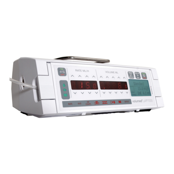
- Page 2 Displays and control elements Volumed® µVP7000 front view Volumed® µVP7000 rear view...
- Page 3 Index numbers Keys: On/Off Start/Stop Bolus / ESC Menu / Select Rate Volume Display elements: Rate window Volume window Information window Alarm window Important mechanical parts: Door Door handle Tube guides Stop flow mechanism (here: Robson clamp, the other option is internal) Air in line detector Pressure sensor Peristaltic mechanism...
-
Page 4: Table Of Contents
Table of Contents 1 TECHNICAL DESCRIPTION ....................4 Control: ............................ 4 Power Supply: .......................... 4 Software: ..........................5 Specifications, instructions for use, warranty, performance data, EMC behaviour: ....5 2 SETUP MODE: ..........................6 2.1 S ..................6 TARTING THE PUMP IN ETUP 2.2 D . -
Page 5: Technical Description
1 Technical description Control: The microprocessor controlled Volumed® µVP7000 is a peristaltic driven infusion pump and intelligent software monitoring of all critical functions. The stepper motor transfers movement to a drive belt, which is directly connected to the finger peristaltic mechanism. All important infusion parameter are displayed on very well readable LCD and LED displays. -
Page 6: Software
There is no physical damage done to the pumps, but the processors need to be reinitialized. Only arcomed ag may carry out the task of re- initialisation. Furthermore are updates only to be carried out by trained personnel. -
Page 7: Setup Mode
With the optional settings the LCD contrast or the language etc. can be changed. Manual changes on the option settings are only possible when address 50 = 0. The optional setting for each configuration can only be changed with arcomed ag own PremiumLink™ software. For the usage of PremiumLink™ separate trainings are highly recommended. -
Page 8: Basic Settings
PCA, 4: TCI, 5: RAM, 6: TOC, 7: PIB, confirm with select. Step2: send the upgrade code, update ID and displayed code to Arcomed, do not switch off device until step 3 is completed. Step 3: enter the ugrade password supplied from Arcomed and confirm with select. -
Page 9: Optional Settings
2.4 Optional Settings This settings can be adjusted over PremiumLink™. For quick checks, the values on address 50 = 0 can be changed. NOTE: Do not forget to put back the default-settings. Address Description Default Backlight on mains, 4099 = 40% night 21h-7h, 99% day 4099 Backlight on battery, 4070 = 40% night 21h-7h, 70% day 4070... - Page 10 How to apply Optional Settings: Optional settings are adjusted via PremiumLink™ where options can be easily selected. Further the configuration via PremiumLink™ ensures a configuration consistency thus increasing patient safety. SH-7000-Pre-E-04/16...
-
Page 11: Trouble Shooting
3 Trouble shooting Fault Cause Action Incorrect giving set Use Arcomed approved set Speed tuning requires adjustment Adjust Speed tuning (address 10) Wrong set selection (in VP7000 Select correct IV brand (address Over Infusion silicone is PVC selected) Worn peristaltic cover... - Page 12 Ultrasonic faces of detector dirty or Clean with soft tissue or cotton bud scratched Faulty detector plates. Replace detector Fluids containing excessive Contact Arcomed representative amounts of air Frequent Air-in Line alarm AIL adapter not positioned properly Replace and realign AIL adapter Display cable defect...
- Page 13 Fault Cause Action Incorrect giving set Use Arcomed approved set Pressure gain (address 15) Adjust Pressure gain adjustment required Constant Worn Peristaltic cover Replace cover occlusion error Pressure transducer not connected Plug in pressure sensor during running Pressure Transducer requires...
- Page 14 Fault Cause Action Replace motor axis, tighten screws Thread in motor axis defect motor axis Bearing next to motor axis defect Replace bearing Pump makes Drive belt too long Replace drive belt clicking noise (also in combination with F-3 error) Drive belt worn out Replace drive belt Ramping...
-
Page 15: Defect Alarms
LCD will display the error code. In such cases the pump must not be used any more until the cause has been checked. If the device cannot be repaired the pump should be sent to technical department or to arcomed ag. Note: On the LITE pumps the defect codes can be viewed in the history file. -
Page 16: Meaning Of Error Codes
4.1 Meaning of error codes: Code Meaning Cause Measure Different Software on Display PCB and Complete SW update Communication Main PCB F-00 error between Main PCB defect Replace Main PCB processors Display PCB defect Replace Display PCB Display cable loose Fix display cable Air detector plate Replace air detector plate... - Page 17 Code Meaning Cause Measure 1min. The Microprocessor detected the key as defect and will give a “Defect”-Alarm. Display PCB is not Mount Display PCB properly mounted properly SW not loaded F-09 CRC - Error Make SW update correctly If persistent, check cable main Internal F-10 Transmit check...
-
Page 18: Watch-Dog On Mainpcb
4.2 watch-dog on MainPCB: On the MainPCB (Version 150305/mvo or later) arcomed implemented a watch-dog to recognize a loss of the battery (during operation on battery-mode) or an unlikely error in the main-processor on the MainPCB. In the rare case of one of these situations, there will be an alarm. -
Page 19: Repairs
5 Repairs The Volumed® µVP7000 Premium may only be serviced by arcomed ag or through arcomed ag trained and licensed personnel. In warranty cases please refer to chapter 6 in the user manual. Please check also chapter 5.11 for additional options that might be installed in your device. - Page 20 Remove four 2.5 mm Hex screws Remove connectors of: Stepper motor (1), DC motor (2), Display print (door) (3), Battery (4) and Front PCB (5). Fitting new main PCB Reassemble pump in reverse order Note: Plug in connector correctly, (see connector pin and hole on the main board) Update the pump following the instructions on chapter 6.4 SH-7000-Pre-E-04/16...
-
Page 21: Dismantling The Door
5.2 Dismantling the Door Tools & recommended spare parts: - Antistatic Work place - 2,5 mm Hex driver - 1 mm Philips screw driver - Door Complete (76390 PVC/EN, 76370 Silicone/EN)) Procedure: Remove the main PCB. Unplug the display ribbon cable from main PCB. Loosen the two screws indicated and carefully remove door from metal rod. - Page 22 Remove the remaining door screws and carefully separate the two halves of the door without damaging the sealing gasket and the Air In Line Detector cables. When reassembling the door, the order of the screws must be observed. The shortest screws must be used at the indicated position. Also pay attention to the positions of the door latches.
-
Page 23: Changing Display Pcb And Front Foil
5.3 Changing Display PCB and Front Foil Tools & recommended spare parts: - Antistatic work place - Phillips screw driver - Display PCB programmed µVP7000 Premium (76290) - Front Foil DATA µVP7000 Premium (76160) - LCD (73165) Procedure: Dismantle door Loosen screws on display PCB Lift off display PCB from front housing. - Page 24 In case the front foil must be changed, take off the old foil with a sharp device. Be careful not to damage the White plastic part. Remove remaining glue and clean the housing. To prevent the LEDs from shining through the front foil, protecting foils are placed underneath the pictograms.
-
Page 25: Dismantle The Pump Block
5.4 Dismantle the Pump Block Tools & recommended spare parts: - Antistatic work place - 2.5 mm Hex driver - 5.5 mm socket wrench - Philips screw driver No. 1 - Pump Block Assembly (76695 PVC, 76685 Silicone) Procedure: Turn off pump and dismantle main PCB Remove Main PCB and store in antistatic environment. -
Page 26: Replacement Of Pressure Sensor
5.5 Replacement of Pressure Sensor Tools & recommended spare parts: - Antistatic work place - 2.5 mm Hex driver - 5.5 mm socket wrench - Philips screw driver No. 1 - Pressure Sensor Kit (75521) Procedure: Dismantle Main PCB Dismantle pump block Unplug pressure sensor cable from Front PCB Front PCB Pressure sensor connector... -
Page 27: Replacement Of Upstream Occlusion Pressure Sensor
5.6 Replacement of Upstream Occlusion Pressure Sensor Tools & recommended spare parts: - Antistatic work place - 2.5 mm Hex driver - 5.5 mm socket wrench - Philips screw driver No. 1 - Pressure sensor Upstream kit µVP7000 (98702) Procedure: Dismantle Main PCB Dismantle pump block Unplug pressure sensor cable from Front PCB... - Page 28 Remove old pressure sensor and place new one Connect pressure sensor cable, built in pump block Adjust upstream occlusion pressure sensor, close housing SH-7000-Pre-E-04/16...
-
Page 29: Replacement Of Stop-Flow Mechanism
5.7 Replacement of Stop-Flow mechanism The Stop-Flow mechanism opens and closes the tubing automatically to prevent free flow if the door is opened by accident. Its function is self-checked every time an infusion is started. Tools & recommended spare parts: - Antistatic work place - 2.5 mm Hex driver - 5.5 mm socket wrench... - Page 30 Carefully remove the 2.5 mm Hex screws as well as the self-tapping screw. Lift the front PCB slightly; be careful not to damage the Hall sensor. 2.5 mm Hex Screws Self Tapping Screw Hall PCB Carefully remove the Stop flow Assembly (Note: tab under front PCB) Loosen the fixing screws of the DC Motor Mount DC Motor to new Stop Flow Housing SH-7000-Pre-E-04/16...
- Page 31 Make sure the Actuator is turned all the way clockwise Correct Wrong Lift the Front PCB slightly and let the tab slide under it. Tighten the Hex screw and Self Tapping screw SH-7000-Pre-E-04/16...
- Page 32 Hold Stop Flow from rear whilst firmly pushing the front part of the Stop Flow Mechanism into the housing. Note: Slide top part up behind actuator first, then push bottom edge back into front housing. Assemble pump in reverse order SH-7000-Pre-E-04/16...
-
Page 33: Replacing The Peristaltic Cover
5.8 Replacing the Peristaltic Cover The peristaltic cover protects the inner part of the pump from dust and liquids and has a great influence on the precision of the pump. By disinfecting the cover with cleaning agents the rubber loses its flexibility, which causes the damage of the cover. Therefore it is necessary to replace the cover when worn. - Page 34 Place new cover in Front Housing Apply a small amount of EP grease to the pump block fingers. Mount pump block and reassemble pump in reverse order. SH-7000-Pre-E-04/16...
-
Page 35: Replacement Of Pb Back Plate And Springs
5.9 Replacement of PB Back Plate and Springs Tools & recommended spare parts: - Antistatic Work place - 5,5 mm Hex driver - 2,5 mm Hex driver - 1,5 mm Hex driver - Phillips screw driver - PB Back plate and Springs are included in Door pressure kit (76331) Procedure: Dismantle main PCB Dismantle pump block... -
Page 36: Changing The Air Detector Plates
5.10 Changing the Air Detector Plates 5.10.1 Part A: Door Air Detector Plate: Tools & recommended spare parts: - Antistatic Work place - Phillips screw driver - Air in Line Detector Kit (76046) Procedure: Dismantling the door Remove transparent foil over the Air detector plate. Loosen and remove the fixing screws of the air detector plate. -
Page 37: Part B: Front Housing Air Detector Plate
5.10.2 Part B: Front Housing Air Detector Plate Tools & recommended spare parts: - Antistatic Work place - Phillips screw driver - 5,5 mm Hex driver - 2,5 mm Hex driver - 1,5 mm Hex driver Procedure: Dismantle Main PCB Dismantle pump block Dismantle Stop Flow Mechanism Remove AIL adaptor and transparent foil over air in line detector plate... -
Page 38: Additional Options And Amendments
5.11 Additional options and amendments 5.11.1 Stop flow counter plate arcomed pumps are fitted with a counter plate to improve the strength of the shafts of the stop flow. During disassembly and assembly the screw holding the counter plate the fixation to the main housing have to be removed and reassembled: Pumps without the stop flow counter plate can be fitted with the counter plate at any time. -
Page 39: Initialisation And Updates
6.1 Release Note PremiumLink™ is arcomed ag own pump update software tool. This program undergoes constant improvements and has different releases. New releases are announced with arcomed ag’s TecUpdate bulletin or can be requested at support@arcomed.com... -
Page 40: Sw Update
6.2 SW Update !!WARNING!!: Pump must be on mains! Turn pump off and connected to mains power Connect USB interface to PC, start PremiumLink™, open set or import .BIN file Select “Update SW”, “Pump Text” and “Auto” in the download to pump section Position IR windows of interface and pump over each other. -
Page 41: Sw Update After Replacement Of Display Pcb
6.3 SW Update after replacement of Display pcb. !!WARNING!!: Pump must be on mains power! Turn pump off and connected to mains power. Connect USB interface to PC, start PremiumLink™, open setStandard. Select “Update SW”, “Pump Text”, “Auto” and “Auto-save config” in the download to pump section Position IR windows of interface and pump over each other. -
Page 42: Sw Update After Replacement Of Main Pcb
18. Select address 52, enter the serial nr. of the device, confirm with “SELECT” 19. Go through all pump calibrations. Go to chapter 7. 20. In order to ensure the proper operation of the pump, perform your operation and safety tests. 21. - Page 43 11. Select address 1 in RATE display, enter the value 9999 in DATA display. In your screen will appear “dàm 9999” confirm with “SELECT” button. Then your calibration data will be transfer from MAIN pcb to DISPLAY pcb. It will take a couple of seconds.
-
Page 44: Calibration
7 Calibration The pump must calibrated with the final user IV set. Only one brand of IV set is allowed. All calibrations must be done with the pump on configuration 0. To start up the pump in Setup Mode, please refer to chapter 2. 7.1 Pressure Sensor The built in pressure sensor of the Volumed®... - Page 45 Using the 0.89 Hex Driver, loosen the adjustment screw a few turns Fixing screw Adjustment screw 0.89mm Hex driver How to position 0.89 mm hex driver to gain access to adjustment screw After reversing the adjustment screw a few turns, the rubber cab of pressure sensor must be pushed in with a piece of metal according to next picture.
- Page 46 Select address 18 Internal stop flow set 18 = 15, Robson set 18 = 115, press Menu and check if actuator makes a full turn (with set/Robson inserted) and doesn’t crash when reaches the stroke end position. Increase or decrease parameter 18 for optimum setting (14 - 18 resp.
- Page 47 7.2 Upstream Occlusion Pressure Sensor The built in upstream occlusion pressure sensor of the Volumed® µVP7000 Chroma has to be adjusted first mechanically and then by means of software. The mechanical adjustment is necessary after replacement or if the software adjustment is not sufficient. Used tools: - 2.5 mm Hex driver - 0,89 mm Hex driver...
-
Page 48: Door Pressure
(up to ± 2% measuring error). Infusion sets have also deviations in the diameter. Both effects influence the calibration of the IV set. If possible work with precision scales and with referenced sets. If in doubt please contact the Arcomed support team. SH-7000-Pre-E-04/16... -
Page 49: Maintenance
Worn or defective parts must be replaced. However, the pumps do not need any regular replacement of specific items. arcomed ag provides service kits and it might be more efficient to use all parts provided in the kits to avoid additional repairs. It is however not mandatory to use all parts in the kits. - Page 50 Functional test Check for Result Open door, insert primed infusion set. Close the door and turn on the pump. An automatic test of the Stop flow mechanism will start. After 10 1 Stop-flow-mechanism seconds the pump must ask for entering the rate and VTBI.
- Page 51 During security check the battery must be checked. If any other than arcomed ag recommended batteries are used, the correct function of the pump cannot be guaranteed. Old batteries must be disposed according to national guidelines.
-
Page 52: Drawings And Layouts
9 Drawings and Layouts Note: Arcomed AG delivers spare part kits rather than individual spare parts. Contact Arcomed AG for the spare parts kits catalogue to determine what ordering number to use. SH-7000-Pre-E-04/16... -
Page 53: History
10 History Version 0416: New Optional settings table in Setup Mode. Battery failure Beep Alarm. New metal Gear wheels on the Drive assy. Sw update procedure. Main and Display pcbs replacement procedure. Calibration procedure. . Includes recommended spare parts on Repair chapter. Chapter 8 Maintenance. Version 0415: Added chapter 5.11 with stop flow counter plate.
Need help?
Do you have a question about the Volumed uVP7000 Premium and is the answer not in the manual?
Questions and answers