
Subscribe to Our Youtube Channel
Related Manuals for NHP ATYSC55CIP


Summary of Contents for NHP ATYSC55CIP
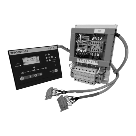
- Page 1 INSTALLATION MANUAL Cat No: ATYSCxxCIP For NHP MCCB BTS up to 3200A Product Specifications ATYSC55CIP ATyS C55 Transfer Switch Control Interface for NHP TB2 and TBP BTS ATYSC65CIP ATyS C65 Transfer Switch Control Interface for NHP TB2 and TBP BTS...
- Page 2 Risk of electrocution, burns or injury to persons and / or damage to equipment. This Installation Manual is intended for personnel trained in the installation and commissioning of this product. For further details refer to the product instruction manual for the C55 & C65 and refer NHP documentation. ATTENTION: This product must always be installed and commissioned by qualified and approved personnel.
-
Page 3: Supplied Items
1 each Loom ATYSC65CIP 16090001 Looms are prewired to CIP Not available separately and controller plugs Required Items Not Supplied Part Number BTSxxxxxxx TemBreak PRO NHP Manufactured Basic Transfer Switch TB2/TBP up to 3200A Scan QR Code for more information... - Page 4 Dimensions ATyS C55/65 Controller 240 mm 63.90 mm 48.10 mm 220 mm Control Interface Panel Dimensions not to scale...
- Page 5 Mounting Panel Remove all connectors then place the ATS controller inside the door cut-out and clip the door mounting screws into the side of the controller (2 screws on each side). It is important to respect the tightening torque indicated below and follow good engineering practise when installing the ATS controller. 220 +/-1 mm Insert the 4 door mounting screws in the designated slot...
- Page 6 Clearances Controller 10 mm 10 mm Cable must be more than 10mm away from the RTC battery cover and USB. Do not drill holes above the controller after it has been mounted, to avoid swarf in terminals Control Interface Panel The below clearance are recommendations to allow for easy of wiring to the Control Interface Panel Recommended clearance for default loom exit...
- Page 7 Plugs Plug the emergency side loom into the right hand side of the BTS (Grey to Grey) Plug the normal side loom into the left hand side of the BTS (Orange to Orange) snap! snap! Both plugs will SNAP into place, Wiring from CIP to BTS COMPLETE! Looms ATYSLOOMA –...
-
Page 8: Network Setting
Fuse Wiring Do not input > 264 VAC (line – neutral) nominal voltage to the Fuse Terminals The C55/65 sensing terminals limits are 88 - 576 VAC, however the CPSR’s coil & standard build BTS are rated for 204 – 264 VAC. The below outlines some of the possible wiring combinations for the Control Interface Panel. - Page 9 Date Format DD/MM/YY If the above settings are not used for an NHP BTS, a trip event on one source could lead to an event where the opposite source breaker will attempt to close and result in jamming of the BTS.
- Page 10 Wizard Once you have selected to start the Wizard you will go through the following 12 windows Smart Config and Manual Config option Date and Time will be important for applications where the logging of events, alarms and faults is critical If SMART Config was selected these fields will be auto filled, it is important to have both Source 1 &...
-
Page 11: Initial Test
Initial Test As well as routine inspection it is also important to test the installation when first commissioning. The below will advise how to perform either a Test On Load (TON) or Test Off Load (TOF). TON is the recommended option however, due to site requirements at the time a TON may not be possible. Test On Load (TON) TEST ON LOAD / LOAD TEST: will perform a full test including all the timers and operating the switch (full cycle). - Page 12 The controller will receive trip feedback from the breakers via inputs 3 and 4, as per NHP factory settings. When a tripping action is detected the controller will inform the user with a pop-up with the information of which breaker has tripped.
- Page 15 Legend...
-
Page 16: Troubleshooting
1010 other users and entering inspection date and telephone number These default passwords can be changed in the Parameters / Passwords menu (Configurator or Maintenance access) NHP Electrical Engineering Products Pty Ltd 1300 NHP NHP nhp.com.au 0800 NHP NHP nhp-nz.com A.B.N.
Need help?
Do you have a question about the ATYSC55CIP and is the answer not in the manual?
Questions and answers