
Related Manuals for NHP TemBreak PRO P


Summary of Contents for NHP TemBreak PRO P
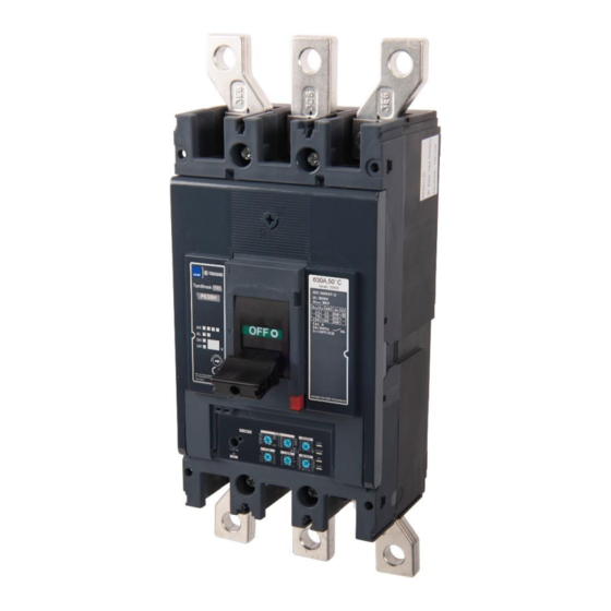
- Page 1 P Model Moulded Case Circuit Breaker Basic Electronic Trip Unit from 160A up to 630A USER MANUAL Version 1.3.0 1300 NHP NHP nhp.com.au NHP Electrical Engineering Products 0800 NHP NHP nhp-nz.com...
-
Page 2: Using This Manual
Appropriate use of NHP / Terasaki products NHP / Terasaki products are intended to be used only for the applications described in the catalogue and technical documentation, which is dedicated to them. If products and components from other manufacturers are used, they must be recommended or approved by NHP or Terasaki. -
Page 3: Summary Of Changes
Summary of Changes This section highlights the details of changes made since the previous issue of this document. The versioning convention used to track changes in this document follows the structure Vx.y.z where: x: Major revision, where extensive changes are made which is generally incompatible with the previous version. Such changes may include new products and/or features, or removal of information which is no longer relevant or applicable to the previous version y: Minor revision, where changes made do not change the overall scope of the previous version, but may include additional information which complements or corrects the previous version, or provides additional clarity on an existing topic. -
Page 4: Table Of Contents
Table of Contents Using this manual Commissioning Safety Precautions LTD Adjustments (I Summary of Changes STD Adjustments (I Table of Contents INST Protection Adjustments (I Introduction INST Protection Only Setting Who Should Use This Manual? LSIG 3P – GF Protection Adjustments (I Additional resources LSIG 4P –... -
Page 5: Introduction
This manual aims to provide users, electricians, panel builders and maintenance personnel, with the technical information required for commissioning and operation of the NHP / Terasaki TemBreak PRO P_BE MCCB. Users of this document must have at minimum a basic understanding of electrical circuit protection topics including (but not limited to):... -
Page 6: Terminology And Abbreviations
Introduction Terminology and Abbreviations Abbreviation Description Abbreviation Description Maintenance Interface Port: Plug for temporary Auxiliary Communications port: Plug for Smart auxiliary / connection to OCR testing, servicing, and maintenance alarm contact block tools Alarm: An auxiliary contact indicating trip status Neutral ASCII American Standard Code for Information Interchange... -
Page 7: Product Information
Product Information The TemBreak PRO P model Basic Electronic MCCB with trip unit type P_BE, in addition to protecting against overloads and short circuits, offers flexibility via provide fully adjustable LSI(G) (long time, short time, instantaneous, ground fault) protection settings via preset rotary switches as well as a host of other standard or optional features. -
Page 8: Part Number Break Down
36 kA 25 kA Switch Notice: Not all combinations are possible. Confirm part number combination with NHP for availability. 160AF only For P_SE versions these features are standard and therefore are not added to the end of the part number. -
Page 9: Available Mccbs In The Tembreak Pro Range
Product Information Available MCCBs in the TemBreak PRO range: Rating Frame Size Short Circuit Break Capacity 1000 1250 1600 2000 2500 3200 (kA) A160E – TF A160E – FF A250E – TM P400E-TM P630E – TM B160E – FF A160F – TF A250F –... -
Page 10: P160_Be And P250_Be Information
Product Information P160_BE and P250_BE Information Frame / Model Attribute Unit Condition P160F P160N P160H P250F P250N P250H Number of Poles 3, 4 3, 4 3, 4 3, 4 3, 4 3, 4 Nominal current ratings 50°C 40 A 40 A 40 A 40 A 40 A... -
Page 11: P400_Be Information
Product Information P400_BE Information Frame / Model Attribute Unit Condition P400F P400N P400H P400S Number of Poles 3, 4 3, 4 3, 4 3, 4 Nominal current ratings 250 A 250 A 250 A 250 A 50°C Calibration Trip unit ratings 400 A 400 A 400 A... -
Page 12: P630_Be Information
Product Information P630_BE Information Frame / Model Attribute Unit Condition P630F P630N P630H P630S Number of Poles 3, 4 3, 4 3, 4 3, 4 Nominal current ratings 50°C 630A 630A 630A 630A Trip unit ratings Calibration Electrical characteristics Rated maximum operational voltage AC 50/60 Hz ─... -
Page 13: Internal Accessories
Internal Accessories Internal accessories include Auxiliary and Alarm contacts, Shunt Trip and Undervoltage Trip (UVT) modules, which may be installed under the front cover of the MCCB in various combinations to provide additional functionality and connection with external control circuits. Auxiliary &... -
Page 14: Shunt Trip
Internal Accessories Shunt Trip A shunt (normally de-energized) can be installed to trip the MCCB by applying voltage to the shunt coil. Part Number Rated voltage Connection Type AC (V) DC (V) T2SH00LA10T ─ Terminal T2SH00LA20T 230…240 ─ Terminal T2SH00LA40T 400…415 ─... -
Page 15: Plugs & Ports
Plugs & Ports The P_BE circuit breaker is equipped with specific connectors for connecting interfacing devices and accessories. Port Description Used to connect the PTA output contact to send the pre-trip alarm over a local signalling circuit. Located on the outside left-hand side of the MCCB. Maintenance Interface Port –... -
Page 16: Installation
Installation Precautions WARNING: To prevent electrical shock and damage to equipment, disconnect and isolate power source upstream of the MCCB before installing or servicing the MCCB including its connected accessories. Notice: To ensure correct performance, and integrity of equipment, the installation instructions and recommendations provided herein shall be respected. -
Page 17: Clearances
Installation Clearances WARNING: Exposed conductors including terminals at attached busbars must be insulated to avoid possible short-circuit or earth faults due any foreign matter coming into contact with the conductors. Phase to Phase and Earth Interruption of large currents during fault or normal switching operation produces ionised gases and arcing materials which expelled from the vents at the top of the MCCB. - Page 18 Installation Insulating Distance When earth metal is installed within proximity of the breakers, the correct insulating distance must be maintained, (refer to Minimum Clearance). This distance is necessary to allow the exhausted arc gases to disperse. This could include the mounting plate or side panel within a switchboard. Minimum Clearance Below illustrates the minimum clearance that must be maintained.
-
Page 19: Internal Accessory Mounting Locations
Installation Internal Accessory Mounting Locations P160, P250 and P400/630 frame sizes have different internal mounting locations for auxiliary contacts, alarm contacts, shunts and, UVTs. Left-side and right-side mounting locations are independent and accept unique combinations. For example, shunts and UVTs may only be mounted on the right side, whereas auxiliary and alarm contacts may be mounted on either left or right side. -
Page 20: P250 Internal Accessories Combination
Installation Internal Accessory Mounting Locations P250 internal accessories combination Legend TemBreak P_BE-UM-001-EN V1.3.0... -
Page 21: P400/630 Internal Accessories Combination
Installation Internal Accessory Mounting Locations P400/630 internal accessories combination Legend Notice: Only 2 internal accessories can be mounted on the right-hand side of a P400 and P630 MCCB. Under no circumstances can 3 or more be installed. Examples: 2 AUX 1 Alarm and 1 AUX 1 Shunt and 1 AUX 1 UVT and 1 AUX... -
Page 22: Alarm, Shunt & Uvt Installation
Installation Alarm, Shunt & UVT Installation The alarm, shunt and UVT have a trip bar that needs to interact with the MCCBs trip mechanism. As such they must be installed in a specific way. Refer to the supplied Installation Instructions for the respective accessories for further detail. Standard Alarm &... -
Page 23: Shunt & Uvt Installation
Installation Alarm, Shunt & UVT Installation Shunt & UVT installation Action Note Switch the Smart MCCB to the Tripped Position. Open the front cover of the MCCB. Locate the shunt or UVT’s trip bar into the MCCB trip mechanism slot. The shunt or UVT will need to be rolled into place, follow the... -
Page 24: Protection Settings
Protection Settings Trip Curve The TemBreak PRO P_BE electronic trip unit protects against overcurrent and short circuit faults for many types of electrical distribution systems. The P_BE OCR has protective characteristics according to the requirements of the standard AS/NZS IEC 60947-2. All protection functions are based on the effective value (RMS) of power, to reduce the effects of current harmonics. -
Page 25: Long Time Delay (Ltd) Protection
Protection Settings Long Time Delay (LTD) protection The Long Time Delay protection protects against current overloads or surges in power distribution or motor control applications. Long Time Delay protection is an inverse-time protection which includes a thermal image function. Long Time Delay Settings Description Long Time Delay protection threshold (current rating) Long Time Delay (time delay) -
Page 26: Adjusting I R (Current)
Protection Settings Long Time Delay (LTD) protection Adjusting I (Current) The LTD protection trip range is: 1.05...1.20 x I according to standard AS/NZS IEC 60947.2. The trip threshold tolerance I for the long-time delay protection is +5% to +20%. The I trip threshold is adjusted using two I dials on the front of the MCCB: –... -
Page 27: Adjusting T R (Time Delay)
Protection Settings Long Time Delay (LTD) protection Adjusting t (Time Delay) The t time delay defines the trip time of the long-time delay protection for a current of 6 x I . and adjustable via the t dial. Adjustment Range (seconds) Notice: For the following MCCBs the setting of I and t can limit the setting of I... -
Page 28: Thermal Memory / Hot-Cold Start Mode
θ is retained if the current drops below the LTD pick-up current threshold (between 1.05…1.20 x I The standard P_BE OCR is supplied with Cold start mode only. If Hot start mode is required, a made-to-order P_BE can be supplied. Contact NHP for details on the Hot start mode option. -
Page 29: Short Time Delay Protection (Std)
Protection Settings Short Time Delay Protection (STD) The short time protection is designed to protect against low level short circuits. Short Time Delay Settings Description (x I Short Time Delay protection threshold (ms) Short Time Delay I²t (ON / OFF) Inverse I²t time TemBreak P_BE-UM-001-EN V1.3.0... -
Page 30: Adjusting I Sd (Current)
Protection Settings Adjusting I (Current) The I trip threshold tolerance for STD protection is ±10%. Adjustments to I can be made via the I adjustment dial, which is represented as a multiple of I For example: I is set to 120A, I dial in position 5 sets I to 5 x 120A = 600A (±10%). -
Page 31: Adjusting T Sd (Time Delay)
Protection Settings Short Time Delay Protection (STD) Adjusting t (Time Delay) The t time delay can be adjusted from the t dial, where the tripping delay is given in milliseconds (ms). An I t function for STD can be enabled by setting the t dial to a value on the right side, or I t disabled by setting a value on the left side. -
Page 32: I 2 T Function For Std
Protection Settings Short Time Delay Protection (STD) t function for STD When enabled, the I²t function for STD may be used to improve selectivity with downstream devices by overlaying a supplementary I t = K curve within the STD tripping section, starting from the I threshold setting up to the I threshold setting. - Page 33 Protection Settings Short Time Delay Protection (STD) t function for STD The I t curve is based on the setting of I The below time current graph illustrates the effect of the I t curves calculated for different I settings. Settings t ONLY Full curve...
-
Page 34: Thermal Self Protection
Protection Settings Short Time Delay Protection (STD) t function for STD Thermal Self Protection Thermal self-protection is enabled automatically where STD is disabled. This is to ensure that the continuation of the LTD curve does not intersect with the Critical Area of the MCCB, which could create overheating stresses in the MCCB and cause irreparable damage and/or undesirable operation or failure of the trip-unit. -
Page 35: Instantaneous Protection (Inst)
Protection Settings Instantaneous Protection (INST) Instantaneous protection is designed to protect against high current short circuits. This protection is independent of time and is set as a multiple of the rated current I Instantaneous Protection Settings Description (x I Instantaneous protection threshold Adjusting I (Current) The l... -
Page 36: Ground/Earth Fault Protection (Gf)
Protection Settings Ground/Earth Fault Protection (GF) Ground Fault (GF) protection is protection against high strength insulation / earth faults. An LSIG P_BE OCR is required for both 3P and 4P MCCBs to permit GF protection. P_BE OCRs with LIS only do not have GF protection. Ground Fault Protection Settings Description = 0.4 x I... -
Page 37: Neutral Protection (Np)
Protection Settings Neutral Protection (NP) Neutral protection is available with 4P P_BE MCCBs with LSIG OCR. It is particularly useful when the cross-section of the neutral conductor is reduced in relation to the phase conductors. Neutral protection is based off the standard LTD and STD protection parameter of the main phases. The I and I parameters for the Neutral pole are adjusted according to the set Neutral Coefficient percentage. -
Page 38: Alarms & Indication
Alarms & Indication The P_BE OCR provides alarming for various types of events based on system status and live monitoring of parameters. There are three types of alarms to indicate OCR health and trip status: System alarm: Correspond to predefined events internal to the OCR. Trip alarm: Provide warning about trip events. -
Page 39: Trip Alarm
Alarms & Indication Trip Alarm The trip alarm on the P_OCR indicates the status of the LTD protection, which if flashing indicates that an LTD trip is imminent. Alarm/Status type LED Status Description Current < 105% x Ir RED Flashing LTD Pick-up Alarm Current ≥... -
Page 40: Pta (Pre-Trip Alarm)
Alarms & Indication PTA (Pre-Trip Alarm) The Pre-Trip Alarm permits monitoring and early warning of overload conditions prior to an actual LTD trip. The PTA setting is defined by two parameters which define the Pre-trip warning and Pre-trip Alarm zones and thus the behaviour of the PTA contact and status LED: PTA current threshold I : Threshold expressed as a percentage of I and is fixed at 80% x I... -
Page 41: Ocr Power Supply
OCR Power Supply Power to the P_BE OCR is self-powered whilst sufficient current is flowing through the MCCB, which provides a minimum power supply to operate and provide alarm and configured protection functions Minimum conditions for energizing the trip unit without an external power supply: Circuit breaker closed Minimum current through the circuit breaker;... -
Page 42: Commissioning
Commissioning WARNING: Before applying power to the MCCB for the first time, an initial inspection must be performed. WARNING: Risk of nuisance tripping. Only qualified personnel are to set the protection levels. Failure to respect these instructions may cause death, serious injuries or equipment damage. -
Page 43: Std Adjustments
Commissioning STD Adjustments (I The STD protection is configured by the I and t adjustment rotary dials, which is performed as follows. Refer to Protection Settings – Short Time Delay Protection (STD) section for further detail on setting I and t Action Note / Illustration Turn the MCCB to the OFF Position... - Page 44 Commissioning INST Protection Adjustments (I The INST protection is configured by the I adjustment rotary dial, which is performed as follows. Refer to Protection Settings – Instantaneous Protection (INST) section for further detail on setting I Action Note / Illustration Turn the MCCB to the OFF Position Open the transparent flap to access li adjustment dials Using a PH1, PH2 or PZ2 size screwdriver, rotate the I...
-
Page 45: Inst Protection Only Setting
Commissioning INST Protection Only Setting The P_BE OCR can be configured for INST protection only by disabling LTD (and STD) protection modes as follows: Refer to Protection Settings – Instantaneous Protection (INST) section for further detail on setting I Action Note / Illustration Turn the MCCB to the OFF Position Open the transparent flap to access l... -
Page 46: Lsig 3P - Gf Protection Adjustments
Commissioning LSIG 3P – GF Protection Adjustments (I On the LSIG 3P variant P_BE MCCB, the GF protection is configured by the GF adjustment rotary dials, which is used to enable or disable GF protection, and is performed as follows. Refer to Protection Settings –... -
Page 47: Lsig 4P - Np And Gf Protection Adjustments (I N, I G )
Commissioning LSIG 4P – NP and GF Protection Adjustments (I On the LSIG 4P variant P_BE MCCB, both NP and GF protection modes are configured by the N (%) adjustment rotary dials, which is performed as follows. Refer to Protection Settings – Ground/Earth Fault Protection (GF) Neutral Protection (NP) sections for further detail on NP and GF protection. -
Page 48: Troubleshooting
Troubleshooting In the event of a problem when using the TemBreak PRO system, this section provides advice on how to resolve issues. Problem description Possible cause Remedial advice Ready LED OFF Insufficient or no power to the Verify power supply requirements. Refer to OCR Power Supply section. - Page 49 Troubleshooting Problem description Possible cause Remedial advice Nuisance tripping due to starting Excessive inrush starting current Review INST and STD protection settings for load type where applicable current due to load type Switching operation of star-delta Verify and correct any issues with star-delta starter wiring with respect to the motor motor starter, incorrect wiring windings and phase sequence.
-
Page 50: Annex A - Dimensions
Annex A – Dimensions P160 Dimensions TemBreak P_BE-UM-001-EN V1.3.0... -
Page 51: P250 Dimensions
Annex A – Dimensions P250 Dimensions TemBreak P_BE-UM-001-EN V1.3.0... -
Page 52: P400 Dimensions
Annex A – Dimensions P400 Dimensions TemBreak P_BE-UM-001-EN V1.3.0... -
Page 53: P630 Dimensions
Annex A – Dimensions P630 Dimensions TemBreak P_BE-UM-001-EN V1.3.0... -
Page 54: Annex B - Trip Curves
To aide in selectivity studies, a trip curve based on the actual settings used can be generated using the software package TemCurve. Contact NHP for details on TemCurve and Selectivity. -
Page 55: Annex C - I 2 T Let-Through Curves
Annex C – I t Let-Through Curves P160_BE TemBreak P_BE-UM-001-EN V1.3.0... -
Page 56: P250_Be
Annex C – I t Let-Through Curves P250_BE TemBreak P_BE-UM-001-EN V1.3.0... -
Page 57: P400_Be
Annex C – I t Let-Through Curves P400_BE TemBreak P_BE-UM-001-EN V1.3.0... -
Page 58: P630_Be
Annex C – I t Let-Through Curves P630_BE TemBreak P_BE-UM-001-EN V1.3.0... -
Page 59: Annex D - Peak Let Through Curves
Annex D – Peak Let Through Curves P160_BE TemBreak P_BE-UM-001-EN V1.3.0... -
Page 60: P250_Be
Annex D – Peak Let Through Curves P250_BE TemBreak P_BE-UM-001-EN V1.3.0... -
Page 61: P400_Be
Annex D – Peak Let Through Curves P400_BE TemBreak P_BE-UM-001-EN V1.3.0... -
Page 62: P630_Be
Annex D – Peak Let Through Curves P630_BE TemBreak P_BE-UM-001-EN V1.3.0... -
Page 63: Annex E - Watts Loss
Annex E – Watts Loss Front Connection Ampere frame Rating Impedance per pole AC Power dissipation per pole Pole numbers AC Power dissipation per product In (A) Z (mΩ) Power (W) Power (W) 40 A 0.35 0.56 1.68 P160 100 A 0.35 3.50 3P / 4P... -
Page 64: Annex F - Rated Temperature Tables
Annex F – Rated Temperature Tables Rated Temperature Rated Current (A) Connection Ampere frame Rated I type 30°C 35°C 40°C 45°C 50°C 55°C 60°C 65°C 70°C P160 100A 160A 100A Front Conn. P250 Rear Conn. 160A 250A 250A P400 400A 258.9 318.5 P630... - Page 65 This page is intentionally left blank TemBreak P_BE-UM-001-EN V1.3.0...
- Page 66 P_BE-UM-001-EN Version 1.3.0 Published 29th April 2021 1300 NHP NHP nhp.com.au NHP Electrical Engineering Products 0800 NHP NHP nhp-nz.com...
Need help?
Do you have a question about the TemBreak PRO P and is the answer not in the manual?
Questions and answers