
Related Manuals for Optek CONTROL 200


Summary of Contents for Optek CONTROL 200
- Page 1 NSTRUCTIONS MANUAL ERSION PN: 1004-1027-02 (-52) ONVERTER ONTROL Part 1 - Hardware Part 2 - Software...
- Page 2 NSTRUCTIONS MANUAL ERSION , 2005 DATED ANUARY PN: 1004-1027-02 (-52) ONVERTER ONTROL Part 1 - Hardware Part 2 - Software (see separate Documentation)
- Page 3 On request this instructions manual is available in different languages and can also be supplied on CD ® (Acrobat Reader 4.0). Our products are under constant development - technical data is subject to change without notice. Essen, January 2005 Instruction Manual C200 Part1 A1.doc optek Danulat GmbH • D-45356 Essen • Germany page 2...
- Page 4 ++31 - (0)344 - 65 39 50 E-mail info@optek.nl optek-Danulat, Inc. N118 W18748 Bunsen Drive Germantown • WI 53022 • USA Phone ++1-262-437-3600 ++1-262-437-3699 E-mail info@optek.com INTERNET: http://www.optek.com Instruction Manual C200 Part1 A1.doc optek Danulat GmbH • D-45356 Essen • Germany page 3...
-
Page 5: Table Of Contents
Relay Contact Protection and Interference suppression Sensor wiring 4.3.1 Wiring of conductivity sensors 4.3.2 Wiring of pH sensors Start-up / Maintenance Start-up Preventive maintenance / repair Spare parts Fax-Reply Form Instruction Manual C200 Part1 A1.doc optek Danulat GmbH • D-45356 Essen • Germany page 4... -
Page 6: Converter Description
Programmed functions are protected from unauthorized alteration by a five-digit security code. Beside that the dual input CONTROL 200 incorporate a real time clock and a logbook which stores data entries for alarm events, sensor errors, power failures and sensor calibrations. -
Page 7: Technical Data
Output current: 0 to 10mA, 0 to 20mA or 4 to 20mA Analog output programmable to any value between 0 and 22mA to indicate system failure Instruction Manual C200 Part1 A1.doc optek Danulat GmbH • D-45356 Essen • Germany page 6... - Page 8 1 to 7200s, programmable in increments of 1s (0 = Off) Derivative: 0.1 to 999.9s programmable in increments of 0.1s, available only for single set point control Auto/Manual: User-programmable Instruction Manual C200 Part1 A1.doc optek Danulat GmbH • D-45356 Essen • Germany page 7...
-
Page 9: Ph - C210, C211 And C221
* Enables connection to glass or enamel pH and reference sensors and Redox (ORP) sensors Specifications may be limited by the pH electrode in use. Refer to corresponding Instruction Manual ! Instruction Manual C200 Part1 A1.doc optek Danulat GmbH • D-45356 Essen • Germany page 8... -
Page 10: Conductivity - C220, C221 And C222
0 to 30 mins. (user-configurable) Specifications may be limited by the sensor in use. Refer to corresponding Instruction Manual for process limit specifications of optek sensor CF60 ! Instruction Manual C200 Part1 A1.doc optek Danulat GmbH • D-45356 Essen • Germany... -
Page 11: Control 200 - Configuration Feasibilities
C200 H ARDWARE Control 200 – configuration feasibilities Depending on the intended use the converter Control 200 is available in 5 different configurations. The main features and connection feasibilities are listed in the following table: Configurations: CONTROL 200 C210 C220... -
Page 12: Mechanical Installation
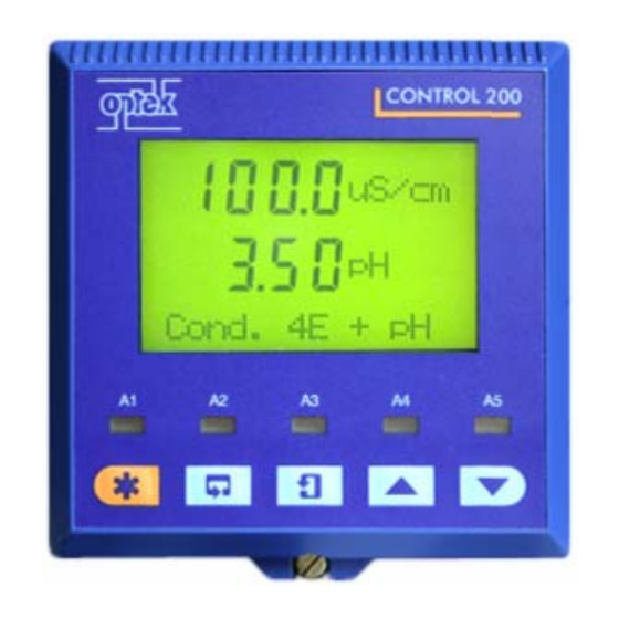
Lines 0.000 uS/cm Units 0.000 Lower uS/cm Display Line Dual Cond. Alarm LEDs Membrane Keys Menu Key Sidescroll Key Downscroll Key Up Key Down Key Instruction Manual C200 Part1 A1.doc optek Danulat GmbH • D-45356 Essen • Germany page 11... -
Page 13: Back Panel Control
Sensor A A14 — C14 — A15 + C15 + Analog Output 2 Analog Output 4 A16 — C16 — Earth (Ground) Stud on Case Instruction Manual C200 Part1 A1.doc optek Danulat GmbH • D-45356 Essen • Germany page 12... -
Page 14: Dimensions Control
Mount away from harmful vapours and/or dripping fluids Where possible, mount the analyzer at eye level to allow an unrestricted view of the front panel displays and controls Instruction Manual C200 Part1 A1.doc optek Danulat GmbH • D-45356 Essen • Germany page 13... -
Page 15: Rack Mounting Control
(92.6 x 92.6 mm). Installation procedure is as described in Section 3.4. Dimensions of the front plate (PN: 1200-3333-0001-00) are shown as follows: Instruction Manual C200 Part1 A1.doc optek Danulat GmbH • D-45356 Essen • Germany page 14... -
Page 16: Field Wiring Schematic
(grounded) metal conduit. Use twisted pair output leads or screened cable with the screen connected to the case earth (ground) stud. Instruction Manual C200 Part1 A1.doc optek Danulat GmbH • D-45356 Essen • Germany page 15... -
Page 17: Relay Contact Protection And Interference Suppression
A – AC Applications B – DC Applications For reliable switching the minimum voltage must be greater than 12V and the minimum current greater than 100mA ! Instruction Manual C200 Part1 A1.doc optek Danulat GmbH • D-45356 Essen • Germany page 16... -
Page 18: Sensor Wiring
For use with different sensors refer to corresponding instruction manual ! If sensor is equipped with a 2-wire temperature compensator, link terminals B9 and B10 (and B1 and B2 if dual input analyzer) ! Instruction Manual C200 Part1 A1.doc optek Danulat GmbH • D-45356 Essen • Germany page 17... -
Page 19: Wiring Of Ph Sensors
4.3.2 Wiring of pH sensors The converter CONTROL 200 can be connected to either a standard pH input or differential pH input. The dual input pH is designed for use with pH electrode systems that incorporate a solution earth (ground) connection to provide low glass impedance and out-of-sample/broken cable warnings. -
Page 20: Start-Up / Maintenance
20 min. to warm-up adjust converter (separate document) document installation (XXX) check readings for correctness release measurement for control purpose Check separate instructions manual for sensors ! Instruction Manual C200 Part1 A1.doc optek Danulat GmbH • D-45356 Essen • Germany page 19... -
Page 21: Preventive Maintenance / Repair
C200 H ARDWARE Preventive maintenance / repair The system Control 200 with installed sensors has been designed for low maintenance operation. Extended quality measures in production, like incoming parts inspection on any component guarantee best possible reliability a) wetted parts Periodical inspection within the scope of normal field maintenance is in most cases sufficient, as long as the wetted materials have been chosen properly. - Page 22 We are using another manufacturer: Please call me. I found the instructions manual for model good not good I suggest following improvements: Best regards Date / Signature Instruction Manual C200 Part1 A1.doc optek Danulat GmbH • D-45356 Essen • Germany page 21...
- Page 23 NSTRUCTIONS MANUAL ERSION , 2004 DATED CTOBER PN: 1004-1027-02 (-52) ONVERTER ONTROL Part 2 - Software Part 1 - Hardware (see separate Documentation)
- Page 24 On request this instructions manual is available in different languages and can also be supplied on CD ® (Acrobat Reader 4.0). Our products are under constant development - technical data is subject to change without notice. Essen, October 2005 Instruction Manual C200 Part2 A1.doc optek Danulat GmbH • D-45356 Essen • Germany page 2...
- Page 25 ++31 - (0)344 - 65 39 50 E-mail info@optek.nl optek-Danulat, Inc. N118 W18748 Bunsen Drive Germantown • WI 53022 • USA Phone ++1-262-437-3600 ++1-262-437-3699 E-mail info@optek.com INTERNET: http://www.optek.com Instruction Manual C200 Part2 A1.doc optek Danulat GmbH • D-45356 Essen • Germany page 3...
- Page 26 Sensor Calibration Conductivity Programming Programming pH 5.1.1 Security Code 5.1.2 Configure Display 5.1.3 Configure Sensors 5.1.4 Configure Diagnostics 5.1.5 Configure Alarms 5.1.5.1 Wash Cycle Configuration Instruction Manual C200 Part2 A1.doc optek Danulat GmbH • D-45356 Essen • Germany page 4...
- Page 27 7.2.3 Checking the Temperature Input Appendix Buffer Solutions pH Automatic Temperature compensation PID Controller Certificates Fax-Reply Form Part 1 - Hardware (refer to separate documentation) Instruction Manual C200 Part2 A1.doc optek Danulat GmbH • D-45356 Essen • Germany page 5...
-
Page 28: Overview Hardware
D – Adjusting and Storing a Parameter Value Parameter X Select New value is automatically stored E – Selecting and Storing a Parameter Choice Instruction Manual C200 Part2 A1.doc optek Danulat GmbH • D-45356 Essen • Germany page 6... -
Page 29: Connection Feasibilities
C200 S OFTWARE Configuration feasibilities Depending on the intended use the converter Control 200 is available in 5 different configurations. The main features and connection feasibilities are listed in the following table: Configurations: CONTROL 200 C210 C220 C211 C221 C222... -
Page 30: Operation
Analog features enabled – see Section 7.3 A: Ref. Checking B: Ref. Checking Dual input analyzer only CONFIG. ALARMS A: Ref. Alarm B: Ref. Alarm (see Fig. 2.3B) Instruction Manual C200 Part2 A1.doc optek Danulat GmbH • D-45356 Essen • Germany page 8... - Page 31 Available only if the Option Board Test Output 4 is fitted and Analog features FACTORY SETTINGS enabled – see Section 7.3 (see Section 7.3, Page 57) 6.1.3, Page 88) Instruction Manual C200 Part2 A1.doc optek Danulat GmbH • D-45356 Essen • Germany page 9...
-
Page 32: Operating Page
0pH for Antimony electrodes. Alarm 3 set to , Section 5) – see Section 2.1.2.6 Wash A3: Type Wash Function Alarm 3 not set to Wash Monitoring pH Instruction Manual C200 Part2 A1.doc optek Danulat GmbH • D-45356 Essen • Germany page 10... -
Page 33: Dual Input Ph
B: Slope & Check Alarm 3 set to , Section 5) – see Section 2.1.2.6 Wash A3: Type Wash Function Alarm 3 not set to Wash Monitoring pH Instruction Manual C200 Part2 A1.doc optek Danulat GmbH • D-45356 Essen • Germany page 11... -
Page 34: Single Input Redox (Orp)
A: mV Offset Alarm 3 set to Wash (A3: Type, Section 5) – see Section 2.1.2.6 Wash Function Alarm 3 not set to Wash. Dual Redox Instruction Manual C200 Part2 A1.doc optek Danulat GmbH • D-45356 Essen • Germany page 12... -
Page 35: Dual Input Redox (Orp)
B: mV Offset Alarm 3 set to Wash (A3: Type, Section 5) – see Section 2.1.2.6 Alarm 3 not set to Wash. Wash Function Dual Redox Instruction Manual C200 Part2 A1.doc optek Danulat GmbH • D-45356 Essen • Germany page 13... -
Page 36: Dual Input Ph And Redox (Orp)
0pH for Antimony electrodes. Alarm 3 set to Wash (A3: Type, Section 5) – see Section 2.1.2.6 Wash Function Alarm 3 not set to Wash. pH/Redox Instruction Manual C200 Part2 A1.doc optek Danulat GmbH • D-45356 Essen • Germany page 14... -
Page 37: Wash Function
Press the DOWN key to abort the wash cycle. The display returns to D u a l R e dox the top of the Operating Page. p H / R e d ox Instruction Manual C200 Part2 A1.doc optek Danulat GmbH • D-45356 Essen • Germany page 15... -
Page 38: Operation Conductivity
– see Section 7.3 T o C O N F I G . O U T P U T S Dual input analyzer only (see Fig. 2.3B) Instruction Manual C200 Part2 A1.doc optek Danulat GmbH • D-45356 Essen • Germany page 16... - Page 39 Test Output 4 Available only if option board fitted and analog features enabled – see Section FACTORY SETTINGS 6.1.3 (see Section 7.3, Page 53) 6.1.3) Instruction Manual C200 Part2 A1.doc optek Danulat GmbH • D-45356 Essen • Germany page 17...
-
Page 40: Operating Page
Note. Displayed only if Initial Charge is set to Yes – see Section 5.2.4 A: Initial Charge See Section 3.1.1. Conductivity VIEW SETPOINTS See Section 4.2 SENSOR CAL. Instruction Manual C200 Part2 A1.doc optek Danulat GmbH • D-45356 Essen • Germany page 18... -
Page 41: Dual Input 4-Pole Conductivity
Note. Displayed only if A4: Type is set to Dosing (see Section 5.2.4) and Initial B: Initial Charge Charge is set to Yes (see Section 5.2.4). Dual Cond. See Section 3.1.1. VIEW SETPOINTS See Section 4.2. SENSOR CAL. Instruction Manual C200 Part2 A1.doc optek Danulat GmbH • D-45356 Essen • Germany page 19... -
Page 42: Operator Views
Note. Alarm 5 available only if option board fitted and analog features enabled – see Section 6.1.3 A5: Setpoint See Section 3.1.2. VIEW OUTPUTS VIEW SETPOINTS SENSOR CAL. See Note on next page. Security Code CONFIG. DISPLAY Instruction Manual C200 Part2 A1.doc optek Danulat GmbH • D-45356 Essen • Germany page 20... - Page 43 Probe Type for both sensors set to Redox or ORP and Enable Cals for both sensors set to No (Section 5.1.3) and Alter Sec. Code set to zero (Section 5.1.8) – see Section 5.1.2 Instruction Manual C200 Part2 A1.doc optek Danulat GmbH • D-45356 Essen • Germany page 21...
-
Page 44: View Outputs
Displays the optional features enabled in the Factory Settings page – see Pb Dp Section 6.1.3. Option Board See Section 3.1.4. VIEW SOFTWARE VIEW HARDWARE SENSOR CAL. See Note on Page 21. Security Code CONFIG. DISPLAY Instruction Manual C200 Part2 A1.doc optek Danulat GmbH • D-45356 Essen • Germany page 22... -
Page 45: View Software
Operating Page (option board not fitted) – see Section 2.1.2. Monitoring Redox Dual Redox VIEW SOFTWARE pH/Redox SENSOR CAL. See Note on Page 21. Security Code CONFIG. DISPLAY Instruction Manual C200 Part2 A1.doc optek Danulat GmbH • D-45356 Essen • Germany page 23... -
Page 46: View Logbook
See Note on Page 21. Security Code CONFIG. DISPLAY Advance to entries 2 to 5. Sen.A Note. If no more entries are stored, the display shows No More Entries. Instruction Manual C200 Part2 A1.doc optek Danulat GmbH • D-45356 Essen • Germany page 24... - Page 47 See Note on Page 21. Security Code CONFIG. DISPLAY Advance to entries 2 to 5. Sen.A Note. If no more entries are stored, the display shows No More Entries. Instruction Manual C200 Part2 A1.doc optek Danulat GmbH • D-45356 Essen • Germany page 25...
-
Page 48: View Clock
Monitoring pH Operating Page – see Section 2.1.2. Monitoring Redox Dual Redox pH/Redox VIEW CLOCK SENSOR CAL. Security Code See Note on Page 21. CONFIG. DISPLAY Instruction Manual C200 Part2 A1.doc optek Danulat GmbH • D-45356 Essen • Germany page 26... -
Page 49: Operator Views Conductivity
Note. Alarm 5 available only if option board fitted and analog features enabled – see Section 6.2.3. A5: Setpoint See Section 3.2.2. VIEW OUTPUTS VIEW SETPOINTS See Section 4.2. SENSOR CAL. Instruction Manual C200 Part2 A1.doc optek Danulat GmbH • D-45356 Essen • Germany page 27... -
Page 50: View Outputs
Displays the optional features enabled in the Factory Settings page – see Section ----- Pb DP 6.1.3. Option Board See Section 3.2.4. VIEW SOFTWARE VIEW HARDWARE See Section 4.2. SENSOR CAL. Instruction Manual C200 Part2 A1.doc optek Danulat GmbH • D-45356 Essen • Germany page 28... -
Page 51: View Software
See Section 4.2. SENSOR CAL. Advance to entries 2 to 10. 2 A1 Note . If no more entries are stored, the display shows No More Entries. Instruction Manual C200 Part2 A1.doc optek Danulat GmbH • D-45356 Essen • Germany page 29... - Page 52 VIEW CLOCK Section 3.2.6. See Section 4.2. SENSOR CAL. Advance to entry 2. Note. If no more entries are stored, the display shows No More Entries. Instruction Manual C200 Part2 A1.doc optek Danulat GmbH • D-45356 Essen • Germany page 30...
-
Page 53: View Logbook
01:02:04 Time Shows the current time. ----- Time 12:00 Operating Page – see Section 2.2.2 Conductivity VIEW CLOCK Dual Cond. See Section 4.2 SENSOR CAL. Instruction Manual C200 Part2 A1.doc optek Danulat GmbH • D-45356 Essen • Germany page 31... -
Page 54: Setup
Buffer Type not set to User – continued on next page. Set Buffer 1 Buffer Type set to User – see Section 4.1.2. A: Enter Point 1 Instruction Manual C200 Part2 A1.doc optek Danulat GmbH • D-45356 Essen • Germany page 32... - Page 55 1, e.g. if buffer 1 is set to 7pH, buffer 2 must be set to at least Set Buffer 2 9pH. Set Auto Buffers Instruction Manual C200 Part2 A1.doc optek Danulat GmbH • D-45356 Essen • Germany page 33...
-
Page 56: Set Up User Defined Buffers
Alter Sec. Code not set to zero (Section 5.1.8) – see Section 5.1.1 SECURITY CODE Alter Sec. Code set to zero (Section 5.1.8) – see Section 5.1.2. CONFIG. DISPLAY Instruction Manual C200 Part2 A1.doc optek Danulat GmbH • D-45356 Essen • Germany page 34... -
Page 57: Adjust Offset
Alter Sec. Code not set to zero (Section 5.1.8) – see Section 5.1.1 CONFIG. DISPLAY Alter Sec. Code set to zero (Section 5.1.8) – see Section 5.1.2. Instruction Manual C200 Part2 A1.doc optek Danulat GmbH • D-45356 Essen • Germany page 35... -
Page 58: Automatic, Single- And Two-Point Calibration
Select Yes or No. ----- A: Abort Cal. Yes selected – return to the main menu. A: SENSOR CAL. No selected – calibration continues. A: Immerse Buf.2 Instruction Manual C200 Part2 A1.doc optek Danulat GmbH • D-45356 Essen • Germany page 36... - Page 59 Alter Sec. Code not set to zero (Section 5.1.8) – see Section 5.1.1 SECURITY CODE Alter Sec. Code set to zero (Section 5.1.8) – see Section 5.1.2. CONFIG. DISPLAY Instruction Manual C200 Part2 A1.doc optek Danulat GmbH • D-45356 Essen • Germany page 37...
-
Page 60: Manual, Single- And Two-Point Calibration
Select Yes or No. A: Abort Cal. Yes selected – return to the main menu. A: SENSOR CAL. No selected – calibration continues. A: Immerse Buf.2 Instruction Manual C200 Part2 A1.doc optek Danulat GmbH • D-45356 Essen • Germany page 38... - Page 61 Alter Sec. Code not set to zero (Section 5.1.8) – see Section 5.1.1 SECURITY CODE Alter Sec. Code set to zero (Section 5.1.8) – see Section 5.1.2. CONFIG. DISPLAY Instruction Manual C200 Part2 A1.doc optek Danulat GmbH • D-45356 Essen • Germany page 39...
-
Page 62: Grab Calibration
Alter Sec. Code not set to zero (Section 5.1.8) – see Section 5.1.1 SECURITY CODE Alter Sec. Code set to zero (Section 5.1.8) – see Section 5.1.2. CONFIG. DISPLAY Instruction Manual C200 Part2 A1.doc optek Danulat GmbH • D-45356 Essen • Germany page 40... -
Page 63: Sensor Calibration Conductivity
Sensor and Temperature Offset = 0.0 Edit selected – continued on next page. Edit A: Sensor Slope Reset selected – continued on next page. Reset A: Reset? Instruction Manual C200 Part2 A1.doc optek Danulat GmbH • D-45356 Essen • Germany page 41... - Page 64 Select Yes and press DOWNSCROLL to reset the calibration data. Select No and press DOWNSCROLL to abort. ----- A: Reset? Return to top of page. Sensor Cal. A Instruction Manual C200 Part2 A1.doc optek Danulat GmbH • D-45356 Essen • Germany page 42...
-
Page 65: Programming
If an incorrect value is entered, access to the configuration SECURITY CODE pages is prevented and the display reverts to the Operating Page – see Section 2.1.2. CONFIG. DISPLAY See Section 5.1.2. Instruction Manual C200 Part2 A1.doc optek Danulat GmbH • D-45356 Essen • Germany page 43... -
Page 66: Configure Display
– Backlight is always on. LED Backlight Return to main menu. CONFIG. DISPLAY Set Backlight See Section 5.1.3. CONFIG. SENSORS Instruction Manual C200 Part2 A1.doc optek Danulat GmbH • D-45356 Essen • Germany page 44... -
Page 67: Configure Sensors
Select No to disable sensor calibration and all associated frames. ----- A: Enable Cals Config. Sensor A CONFIG. SENSORS Return to main menu. See Section 5.1.4. CONFIG. ALARMS Instruction Manual C200 Part2 A1.doc optek Danulat GmbH • D-45356 Essen • Germany page 45... - Page 68 Enter the temperature of the sample within the range –10.0 to 120.0°C. 25.0 Deg.C A: Preset Temp. continued on next page. A: Set Min Slope Instruction Manual C200 Part2 A1.doc optek Danulat GmbH • D-45356 Essen • Germany page 46...
- Page 69 A: Set Min Slope Sensor B (dual input analyzers only) configuration is identical to Config. Sensor B Config. Sensor A Sensor A configuration. See Section 5.1.4. CONFIG. DIAGS Instruction Manual C200 Part2 A1.doc optek Danulat GmbH • D-45356 Essen • Germany page 47...
-
Page 70: Configure Diagnostics
A: Ref. Alarm Sensor B (dual input analyzers only) configuration is identical to Config. Sensor B Config. Sensor A Sensor A configuration. See Section 5.1.5. CONFIG. ALARMS Instruction Manual C200 Part2 A1.doc optek Danulat GmbH • D-45356 Essen • Germany page 48... -
Page 71: Configure Alarms
A–B is displayed only when Probe Type for each sensor is set to pH – see Section 5.1.3. Continued on next page. A1: Failsafe Instruction Manual C200 Part2 A1.doc optek Danulat GmbH • D-45356 Essen • Germany page 49... - Page 72 Config. Alarm 2 fitted and analog features enabled – see Section 6.1.3) is identical to Config. Alarm 1 Alarm 1 configuration. See Section 5.1.6. CONFIG. OUTPUTS Instruction Manual C200 Part2 A1.doc optek Danulat GmbH • D-45356 Essen • Germany page 50...
-
Page 73: Wash Cycle Configuration
Recovery Period Configure Alarm 4. Config. Alarm 4 Config. Alarm 3 See Section 5.1.6. CONFIG. OUTPUTS Frequency Wash Duration Recovery Period Continuous 1s 1s Pulsed Instruction Manual C200 Part2 A1.doc optek Danulat GmbH • D-45356 Essen • Germany page 51... - Page 74 LED Off Delay Relay De-energized, LED On Relay De-energized, LED On Process Variable High Set Point Hysteresis Relay Energized, LED Off Delay Relay De-energized, LED On Instruction Manual C200 Part2 A1.doc optek Danulat GmbH • D-45356 Essen • Germany page 52...
-
Page 75: Configure Outputs
Deg. F 32.0 to 302.0 (minimum differential,18°F) – 0.00 to 14.00 pH (minimum differential, 2.00pH) Note. A-B is applicable only to dual input analyzers. Continued on next page. AO1: Zero Value Instruction Manual C200 Part2 A1.doc optek Danulat GmbH • D-45356 Essen • Germany page 53... - Page 76 Single input analyzer and option board not fitted – see PID Control CONFIG. SECURITY Supplement (IM/AX4PID). Dual input analyzer and option board not fitted – see Section 5.8. Instruction Manual C200 Part2 A1.doc optek Danulat GmbH • D-45356 Essen • Germany page 54...
-
Page 77: Configure Clock
Press to Set and Press to Abort are shown alternately on the lower display line. Press To Set Press To Abort Press the appropriate key to set the clock or abort the changes. Set Clock? Instruction Manual C200 Part2 A1.doc optek Danulat GmbH • D-45356 Essen • Germany page 55... -
Page 78: Configure Security
Use the UP and DOWN keys to to set the logbook On or Off. ----- If Off is selected, all data entries in the logbook are cleared. Logbook Return to main menu. CONFIG. LOGBOOK See Section 5.1.10. TEST/MAINTENANCE Instruction Manual C200 Part2 A1.doc optek Danulat GmbH • D-45356 Essen • Germany page 56... -
Page 79: Test Outputs And Maintenance
Hold Outputs set to Off or On – return to main menu. Maintenance Hold Outputs set to Auto. – continued on next page Automatic Time Instruction Manual C200 Part2 A1.doc optek Danulat GmbH • D-45356 Essen • Germany page 57... - Page 80 Press UP to Set and Press DOWN to Abort are displayed alternately on the lower display line. TEST/MAINTENANC Press the appropriate key to load/save the configuration or abort the changes. Instruction Manual C200 Part2 A1.doc optek Danulat GmbH • D-45356 Essen • Germany page 58...
-
Page 81: Programming Conductivity
If an incorrect value is entered, access to the configuration pages is prevented and the display reverts to the Operating Page – see Section SECURITY CODE 2.2.2. CONFIG. DISPLAY See Section 5.2.2 Instruction Manual C200 Part2 A1.doc optek Danulat GmbH • D-45356 Essen • Germany page 59... -
Page 82: Configure Display
– Backlight is always on. LED Backlight Return to main menu. CONFIG. DISPLAY Set Backlight See Section 5.2.3. CONFIG. SENSORS Instruction Manual C200 Part2 A1.doc optek Danulat GmbH • D-45356 Essen • Germany page 60... -
Page 83: Configure Sensors
A: Temp.Comp A: Analyzer Type set to Cond – continued on next page. A: Concentration A: Analyzer Type set to Conc – continued on page 62. Instruction Manual C200 Part2 A1.doc optek Danulat GmbH • D-45356 Essen • Germany page 61... - Page 84 A: Filter Time Sensor B configuration (dual input analyzers only) is identical to Config. Sensor B Config. Sensor A Sensor A configuration. See Section 5.2.4 CONFIG. ALARMS Instruction Manual C200 Part2 A1.doc optek Danulat GmbH • D-45356 Essen • Germany page 62...
- Page 85 A: Filter Time Sensor B configuration (dual input analyzers only) is identical to Config. Sensor B Config. Sensor A Sensor A configuration. See section 5.2.4. CONFIG. ALARMS Instruction Manual C200 Part2 A1.doc optek Danulat GmbH • D-45356 Essen • Germany page 63...
- Page 86 A: Filter Time Sensor B configuration (dual input analyzers only) is identical to Config. Sensor B Sensor A configuration. Config. Sensor A See Section 5.2.4. CONFIG. ALARMS Instruction Manual C200 Part2 A1.doc optek Danulat GmbH • D-45356 Essen • Germany page 64...
- Page 87 Select Yes to manually define a 6-point concentration curve, otherwise select ----- Concentration Yes selected – continued on next page. A: Enter Point 1 No selected – continued on page 63. A: User Units Instruction Manual C200 Part2 A1.doc optek Danulat GmbH • D-45356 Essen • Germany page 65...
- Page 88 Enter the conductivity and concentration values for the remaining points in the 20.0 user-defined concentration compensation curve. A: Enter point 6 Continued on next page. A: User Units Instruction Manual C200 Part2 A1.doc optek Danulat GmbH • D-45356 Essen • Germany page 66...
- Page 89 A: Filter Time Sensor B configuration (dual input analyzers only) is identical to Config. Sensor B Config. Sensor A Sensor A configuration. See Section 5.2.4. CONFIG. ALARMS Instruction Manual C200 Part2 A1.doc optek Danulat GmbH • D-45356 Essen • Germany page 67...
-
Page 90: Configure Alarms
Off or Status selected – return to top of page. Config. Alarm 1 Alarm selected – continued on next page. A1: Assign Dosing selected – see Section 5.2.4.2. A1: Failsafe Instruction Manual C200 Part2 A1.doc optek Danulat GmbH • D-45356 Essen • Germany page 68... - Page 91 Alarms 4 and 5 if option board fitted and analog features enabled – see Section 6.2.3) is identical to Alarm 1. Config. Alarm 1 See Section 5.2.5. CONFIG. OUTPUTS Instruction Manual C200 Part2 A1.doc optek Danulat GmbH • D-45356 Essen • Germany page 69...
-
Page 92: Configure Cip Interface Alarm
Initial Charge Time Set the initial charge period, between 1 and 30 minutes in 1 minute increments. Mins Init. Charge Time Continued on next page. Dosing Instruction Manual C200 Part2 A1.doc optek Danulat GmbH • D-45356 Essen • Germany page 70... - Page 93 Set the required delay, between 0 and 60 seconds in 1 second increments. Continued on next page. Config. Alarm 1 Config. Alarm 2 See Section 5.2.5. CONFIG. OUTPUTS Instruction Manual C200 Part2 A1.doc optek Danulat GmbH • D-45356 Essen • Germany page 71...
-
Page 94: Configure Cip Status Alarm
Low Alarm error message is displayed (see Table 7.2.1). Off, Status or CIP Status selected – return to top of page. Config. Alarm 2 Alarm selected – see Section 5.2.4.1. A2: Assign Instruction Manual C200 Part2 A1.doc optek Danulat GmbH • D-45356 Essen • Germany page 72... - Page 95 C200 S OFTWARE Instruction Manual C200 Part2 A1.doc optek Danulat GmbH • D-45356 Essen • Germany page 73...
- Page 96 LED Off Delay Relay De-energized, LED On Relay De-energized, LED On Process Variable High Set Point Hysteresis Relay Energized, LED Off Delay Relay De-energized, LED On Instruction Manual C200 Part2 A1.doc optek Danulat GmbH • D-45356 Essen • Germany page 74...
-
Page 97: Configure Outputs
Note. Sen.B and Temp.B are applicable only to dual input analyzers. Range 0-20mA Set the analog output current range for the selected output. 0-10mA ----- 4-20mA AO1: Range Continued on next page. AO1: Span Value Instruction Manual C200 Part2 A1.doc optek Danulat GmbH • D-45356 Essen • Germany page 75... - Page 98 Single input analyzer and option board not fitted – see Section 5.2.7. CONFIG. SECURITY Dual input analyzer and option board not fitted – see Section 5.2.8. Instruction Manual C200 Part2 A1.doc optek Danulat GmbH • D-45356 Essen • Germany page 76...
-
Page 99: Configure Clock
Press UP to Set and Press DOWN to Abort are shown alternately on the lower Press To Set display line. Press To Abort Press the appropriate key to set the clock or abort the changes. Set Clock? Instruction Manual C200 Part2 A1.doc optek Danulat GmbH • D-45356 Essen • Germany page 77... -
Page 100: Configure Control
----- – Disables the controller – Single PID controller Controller PID Controller Controller set to PID – see Section 5.2.7.1. CONFIG. SECURITY See Section 5.2.8. Instruction Manual C200 Part2 A1.doc optek Danulat GmbH • D-45356 Essen • Germany page 78... -
Page 101: Configure Single Pid Controller
Cycle Time Output Type set to Analog – continued on next page. Output Range Output Type set to Pulse – continued on page 81. Pulses/Minute Instruction Manual C200 Part2 A1.doc optek Danulat GmbH • D-45356 Essen • Germany page 79... - Page 102 Analog Output Set the analog current output range. 4-20mA 0-20mA ---- 0-10mA Output Range PID Controller See Section 5.2.7.2. Power Recovery See Section 5.2.8. CONFIG. SECURITY Instruction Manual C200 Part2 A1.doc optek Danulat GmbH • D-45356 Essen • Germany page 80...
- Page 103 Output = 100% 0.3s 0.2s 0.3s 0.2s De-energized Pulse Frequency = 120 pulses per minute See Section 5.2.7.2. Power Recovery See Section 5.2.8. CONFIG. SECURITY Instruction Manual C200 Part2 A1.doc optek Danulat GmbH • D-45356 Essen • Germany page 81...
-
Page 104: Configure Power Failure Recovery Mode
100% in 0.1% increments. Note. A setting of 0% represents no output. Default Output Power Recovery Return to main menu. CONFIG. CONTROL See Section 5.2.8. CONFIG. SECURITY Instruction Manual C200 Part2 A1.doc optek Danulat GmbH • D-45356 Essen • Germany page 82... -
Page 105: Configure Security
Use the and keys to to set the logbook On or Off. ----- If Off is selected, all data entries in the logbook are cleared. Logbook Return to main menu. CONFIG. LOGBOOK See Section 5.2.10. TEST/MAINTENANCE Instruction Manual C200 Part2 A1.doc optek Danulat GmbH • D-45356 Essen • Germany page 83... -
Page 106: Test Outputs And Maintenance
Hold Outputs set to Off or On – return to main menu. Maintenance Hold Outputs set to Auto. – continued on next page Automatic Time Instruction Manual C200 Part2 A1.doc optek Danulat GmbH • D-45356 Essen • Germany page 84... - Page 107 Press UP to Set and Press DOWN to Abort are displayed alternately on the lower display line. TEST/MAINTENANC Press the appropriate key to load/save the configuration or abort the changes. Instruction Manual C200 Part2 A1.doc optek Danulat GmbH • D-45356 Essen • Germany page 85...
-
Page 108: Calibration
Analog-to-Digital converter chip self-compensates for zero and span drift. It is therefore unlikely that the calibration will change over time. • Do Not attempt recalibration without first contacting optek. • Do Not attempt recalibration unless the input board has been replaced or the Factory Calibration tampered with. -
Page 109: Preparation
2) Connect the millivolt source to terminals B14 (–ve) and B16 (+ve) to simulate the pH or Redox input. Connect the millivolt source earth to the Case Earth (Ground) Stud – see Manual CONTROL 200 Part 1 - Hardware. 3) Connect the 0 to 10kΩ decade resistance box to terminals B9 and B11 to simulate the Pt100/Pt1000/Balco 3K. -
Page 110: Factory Settings
Option Board is fitted. Available only if the Option Board is fitted and Analog features enabled – see Section 7.3 Dual input analyzer only Instruction Manual C200 Part2 A1.doc optek Danulat GmbH • D-45356 Essen • Germany page 88... - Page 111 The display advances automatically to the next step once a stable and valid value is recorded. A:T.Zero (100R) Continued on next page. A: T.Zero (1K0) Instruction Manual C200 Part2 A1.doc optek Danulat GmbH • D-45356 Essen • Germany page 89...
- Page 112 – after completion of A:mV Span (+1V) frame – the display returns to CAL. SENSOR A the Calibrate Sensor A page. No selected – calibration continues from the point at which the DOWNSCROLL key was pressed. Instruction Manual C200 Part2 A1.doc optek Danulat GmbH • D-45356 Essen • Germany page 90...
- Page 113 Option Board Option board not fitted – see next page. Alter Fact. Code Monitoring pH Operating Page – see Section 2.1.2. Monitoring Redox Dual Redox pH/Redox Instruction Manual C200 Part2 A1.doc optek Danulat GmbH • D-45356 Essen • Germany page 91...
- Page 114 Set the factory settings access code to a value between 0000 and 19999. Alter Fact. Code FACTORY SETTINGS Return to main menu. Monitoring pH Monitoring Redox Operating Page – see Section 2.1.2. Dual Redox pH/Redox Instruction Manual C200 Part2 A1.doc optek Danulat GmbH • D-45356 Essen • Germany page 92...
-
Page 115: Calibration Conductivity
Analog-to-Digital converter chip self-compensates for zero and span drift. It is therefore unlikely that the calibration will change over time. • Do Not attempt recalibration without first contacting optek. • Do Not attempt recalibration unless the input board has been replaced or the Factory Calibration tampered with. -
Page 116: Preparation
Select the FACTORY SETTINGS page and carry out Section 7.2.3. Temperature Conductivity Cell Simulator Simulator Earth Sensor A Terminal Numbers B11 B12 Sensor B Terminal Numbers Terminal link Instruction Manual C200 Part2 A1.doc optek Danulat GmbH • D-45356 Essen • Germany page 94... -
Page 117: Factory Settings
Available only if the option board is fitted and analog features enabled – see page 58 Dual input analyzer only Instruction Manual C200 Part2 A1.doc optek Danulat GmbH • D-45356 Essen • Germany page 95... - Page 118 The display advances automatically to the next step once a stable and valid value is recorded. A: Res 250 ohm Continued on next page. A: Res 25 ohm Instruction Manual C200 Part2 A1.doc optek Danulat GmbH • D-45356 Essen • Germany page 96...
- Page 119 The display advances automatically to the next step once a stable and valid value is recorded. A:T.Span (1K5) Continued on next page. A: Ref. Checking Instruction Manual C200 Part2 A1.doc optek Danulat GmbH • D-45356 Essen • Germany page 97...
- Page 120 – after completion of A: Res 0.5 ohm frame – the display returns to CAL. SENSOR A the Calibrate Sensor A page. No selected – calibration continues from the point at which the DOWNSCROLL key was pressed. Instruction Manual C200 Part2 A1.doc optek Danulat GmbH • D-45356 Essen • Germany page 98...
- Page 121 Cal. Output 2 Option Board Option board not fitted – see next page. Alter Fact. Code Operating Page – see Section 2.2.2. Conductivity Dual Cond. Instruction Manual C200 Part2 A1.doc optek Danulat GmbH • D-45356 Essen • Germany page 99...
- Page 122 Set the factory settings access code to a value between 0000 and 19999. 0000 Alter Fact. Code Return to main menu. FACTORY SETTINGS Operating Page – see Section 2.2.2. Conductivity Dual Cond. Instruction Manual C200 Part2 A1.doc optek Danulat GmbH • D-45356 Essen • Germany page 100...
-
Page 123: Fault Indication
If erroneous or unexpected results are obtained, the fault may be indicated in the Operating Page by an error message – see Table below. However, some faults may cause problems with analyzer calibration or give discrepancies when compared with independent laboratory measurements. Instruction Manual C200 Part2 A1.doc optek Danulat GmbH • D-45356 Essen • Germany page 101... -
Page 124: Calibration Fail Message Or No Response To Ph/Redox Changes
Check that the analyzer responds to a millivolt input. Connect a pH simulator, such as Model 2410, to the transmitter input; +ve to glass and –ve to reference – see Manual CONTROL 200 Part 1 - Hardware. Select the CONFIG. -
Page 125: Fault Finding Conductivity
If the analyzer passes check a) but fails check b), check the cable connections and condition. If the response for both checks is correct, replace the conductivity cell. Instruction Manual C200 Part2 A1.doc optek Danulat GmbH • D-45356 Essen • Germany page 103... -
Page 126: Checking The Temperature Input
– see Table. Incorrect readings usually indicate an electrical calibration problem. Re-calibrate the analyzer as detailed in Section 6.2.3. Instruction Manual C200 Part2 A1.doc optek Danulat GmbH • D-45356 Essen • Germany page 104... -
Page 127: Appendix
Tables A1 to A5 include the pH values for ABB, DIN, Merck, NIST, and US Technical buffer solutions. Standards are for 4, 7 and 9pH values, from 0 to 95°C (32 to 203°F). Instruction Manual C200 Part2 A1.doc optek Danulat GmbH • D-45356 Essen • Germany page 105... - Page 128 C200 S OFTWARE Instruction Manual C200 Part2 A1.doc optek Danulat GmbH • D-45356 Essen • Germany page 106...
-
Page 129: Automatic Temperature Compensation
One of these measurements could be made at the ambient temperature and the other obtained by heating the sample. τ Temperature coefficient (%/°C) = x 100. Instruction Manual C200 Part2 A1.doc optek Danulat GmbH • D-45356 Essen • Germany page 107... -
Page 130: Pid Controller
C200 S OFTWARE PID Controller Instruction Manual C200 Part2 A1.doc optek Danulat GmbH • D-45356 Essen • Germany page 108... - Page 131 C200 S OFTWARE Instruction Manual C200 Part2 A1.doc optek Danulat GmbH • D-45356 Essen • Germany page 109...
- Page 132 The analyzer is now ready for fine tuning by small adjustments to the P, I and D terms, after the introduction of a small disturbance of the set point. Instruction Manual C200 Part2 A1.doc optek Danulat GmbH • D-45356 Essen • Germany page 110...
- Page 133 C200 S OFTWARE Instruction Manual C200 Part2 A1.doc optek Danulat GmbH • D-45356 Essen • Germany page 111...
-
Page 134: Certificates
C200 S OFTWARE Certificates Certificate DIN EN ISO 9001 : 2000 Instruction Manual C200 Part2 A1.doc optek Danulat GmbH • D-45356 Essen • Germany page 112... -
Page 135: Fax-Reply Form
We are using another manufacturer: Please call me. I found the instructions manual for model good not good I suggest following improvements: Best regards Date / Signature Instruction Manual C200 Part2 A1.doc optek Danulat GmbH • D-45356 Essen • Germany page 113...
Need help?
Do you have a question about the CONTROL 200 and is the answer not in the manual?
Questions and answers