Table of Contents
Advertisement
Advertisement
Table of Contents

Subscribe to Our Youtube Channel
Related Manuals for Optek 156


Summary of Contents for Optek 156
- Page 1 C4121 and C4151 Instruction Manual optek-converter 156 optek-Manual--1004-1022-02--156-US-2017-12-11 PN: 1004-1022-02 (-52) optek-Danulat GmbH Emscherbruchallee 2 45356 Essen Germany Phone: +49-(0)201-63409-0 E-Mail: info@optek.de Internet: www.optek.com...
- Page 2 This instruction manual is written to assist the user in proper procedures for trouble-free operation. It is explicitly pointed out that optek-Danulat GmbH assumes no responsibility for loss or damage caused due to improper use of this instruction manual or products described herein.
-
Page 3: Table Of Contents
Mounting with mounting assembly ..................18 Wiring ............................. 19 General advice on wiring ....................19 Connecting the voltage supply 115 or 230 V AC ..............20 Connecting the voltage supply 24 V AC / DC (option)............20 - I - optek-Manual--1004-1022-02--156-US-2017-12-11 www.optek.com... - Page 4 Table of contents Connecting the sensor ....................... 21 8.4.1 Wiring plan AF56 to 156 converter ................. 23 8.4.2 Wiring plan AS56 to 156 converter ................. 24 Connecting the relay outputs ..................... 25 Connecting the mA-output ....................27 Commissioning ........................28 Requirements for commissioning ..................
-
Page 5: Using The Instruction Manual
Using the instruction manual Validity of the instruction manual This instruction manual is valid for the optek-converter 156 only. Follow the instruction manual for every operation. If the converter is not used as described in this instruction manual, your safety and the converter function could be affected. -
Page 6: Pictograms And Signal Words
If the possible cause of risk can be specified, the corresponding pictogram preceeds instructions: Danger! Electrical voltage. This pictogram indicates danger due to electrical voltage. Caution! This pictogram indicates information on how to avoid material damage. Note! This pictogram indicates instructional or general advice. - 2 - optek-Manual--1004-1022-02--156-US-2017-12-11 www.optek.com... -
Page 7: Returns And Disposal
For disposal, disassemble the system components and separate them according to different material groups. Dispose of materials according to national and local regulations. If no agreement has been made, products may be shipped to optek for disposal. - 3 - optek-Manual--1004-1022-02--156-US-2017-12-11... -
Page 8: Intended Use
The manufacturer is not liable for damage resulting from use contrary to inten- ded use. Following this instruction manual is part of the intended use. The content of all serial number plates on optek products is model specific and refers to the time of delivery. - 4 - optek-Manual--1004-1022-02--156-US-2017-12-11 www.optek.com... -
Page 9: Safety
Have faulty parts of the measuring system replaced immediately. Spare parts must comply with the technical requirements defined by optek. This is always guaranteed when using original spare parts. For maintenance and repair activities, attach a warning sign to the external release device to prevent re-commissioning of the converter. -
Page 10: Safety Instructions For Works On Electrical Equipment
Use only original fuses with specified current and triggering characteristics! When a fuse has to be exchanged, first try to detect the cause and clear the fault before exchanging the fuse. When work on live parts is necessary, use insulated tools only. - 6 - optek-Manual--1004-1022-02--156-US-2017-12-11 www.optek.com... -
Page 11: Description Of The Converter
The converter determines the change of light intensity by means of photocurrent transmitted by the sensor. After taking the logarithm, a measurement signal proportional to the concentration in the process medium is obtained. The 156 provides four defined and one variable measuring range to be adjusted to your specific process parameters. -
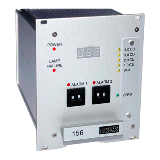
Page 12: Converter Front View
Description of the converter Converter front view Fig. 2 156 converter Numbers stand for: 1. Digital read-out, LED display, 3 digits, height: 7 mm 2. 5 LEDs (yellow), indication of set measuring range 3. LED (red), switch indicator for alarm 2 4. -
Page 13: Converter Rear View
MADE IN GERMANY Fig. 3 Converter rear view Numbers stand for: 16. Potentiometer for lamp voltage 17. Lamp output (only for optek-sensors) 18. mA-output (4 - 20 mA) 19. Relay output 1 20. Relay output 2 21. Relay output 3 22. -
Page 14: Technical Data
Sensor-inputs: 1 for optek photometric sensor AF56 or AS56 Sensor lamp-outputs: 1 lamp supply for optek photometric sensor AF56 or AS56 4.8 ... 7.0 V DC mA-outputs: 1 x 4 - 20 mA functionally galvanically isolated (min. 500 V DC) for connection to PELV - accuracy: <... -
Page 15: Possible Sensors
Technical data Possible sensors One or more of the following optek-sensors can be connected to the converter: • AF56-N • AF56-F • AS56-N • AS56-F Connecting flameproof sensors to the converter is prohibited. The meaning of the sensor options is described in the sensor manuals. -
Page 16: Converter Dimensions
Technical data Converter dimensions POWER 500 ppm 250 ppm LAMP 100 ppm FAILURE 50 ppm ALARM 1 ALARM 2 ZERO optek 106.3mm [4.19“] 190mm [7.48“] 18mm [0.71“] Fig. 4 Dimensions - 12 - optek-Manual--1004-1022-02--156-US-2017-12-11 www.optek.com... -
Page 17: Dimensions For Wall Mount Housing B19-21 - Plastic (Abs) - Ip66 (Option)
Dimensions for wall mount housing B19-21 - plastic (ABS) - IP66 (option) POWER 24.8 LAMP FAILURE ALARM 1 ALARM 2 ZERO optek 176mm [6.93"] 81mm [3.19"] 192.7mm [7.59"] 287mm [11.3"] 206mm [8.11"] 2x M20 4x M16 Fig. 5 Dimensions with wall mount housing B19-21 - 13 - optek-Manual--1004-1022-02--156-US-2017-12-11 www.optek.com... -
Page 18: Dimensions For Wall Mount Housing B19-42 - Plastic (Abs) - Ip66 (Option)
FAILURE ALARM 1 ALARM 2 ALARM 1 ALARM 2 ZERO ZERO optek optek 323mm [12.72"] 340mm [13.39"] 353mm [13.9"] 8x M16 4x M20 81mm [3.19"] 287mm [11.3"] Fig. 6 Dimensions with wall mount housing B19-42 - 14 - optek-Manual--1004-1022-02--156-US-2017-12-11 www.optek.com... -
Page 19: Dimensions For Wall Mount Housing S19-42 - Stainless Steel 1.4301/Ss304 - Ip65 (Option)
323mm [12.72"] 340mm [13.39"] 353mm [13.9"] 10x M16 4x M20 65mm [2.56"] 271mm [10.67"] 295mm [11.61"] 301mm [11.85"] Fig. 7 Dimensions with wall mount housing S19-42 - stainless steel 1.4301 / SS304 - IP65 - 15 - optek-Manual--1004-1022-02--156-US-2017-12-11 www.optek.com... -
Page 20: Dimensions For Mounting With Mounting Angle
Dimensions for mounting with mounting angle 92mm [3.62"] max. 111mm [max. 4.37"] max. 298mm [max. 11.73"] 6.5mm [0.26"] min. 34mm [min. 1.34"] 60mm [2.36"] min. 221mm [min. 8.7"] Fig. 8 Dimensions for mounting with mounting angle W19 - 16 - optek-Manual--1004-1022-02--156-US-2017-12-11 www.optek.com... -
Page 21: Installation Of The Converter
• Screw driver Tool Standard installation 1. Insert the converter into the cutout in the control cabinet. 2. Fasten the four screws M2.5 x 11 (31, fig. 9) of the converter. Fig. 9 Front view with screws - 17 - optek-Manual--1004-1022-02--156-US-2017-12-11 www.optek.com... -
Page 22: Requirements For Mounting With Mounting Angle
2. Mount the mounting assembly with the large side in a horizontal position. 3. Fix the converter at the right side to the mounting assembly. Fasten the four screws on mounting assembly and converter. - 18 - optek-Manual--1004-1022-02--156-US-2017-12-11 www.optek.com... -
Page 23: Wiring
• The power supply socket is not provided with a first-to-mate last-to-break protective ground contact. You must therefore provide an external release device. • The converter is designed for continuous operation and has only to be switched voltage-free for maintenance purposes. - 19 - optek-Manual--1004-1022-02--156-US-2017-12-11 www.optek.com... -
Page 24: Connecting The Voltage Supply 115 Or 230 V Ac
2. Connect the power supply to the power supply socket (24). LAMP - VOLTAGE 24V DC 50/60Hz, 30VA 24V, T1,25A OPTEK-DANULAT MADE IN GERMANY Fig. 12 Connecting the power supply 24 V AC / DC - 20 - optek-Manual--1004-1022-02--156-US-2017-12-11 www.optek.com... -
Page 25: Connecting The Sensor
50/60Hz, 30VA 115VAC, T0,630A 230VAC, T0,315A 230V OPTEK-DANULAT MADE IN GERMANY Fig. 13 Detector inputs and lamp outputs of the converter 156 Letters stand for • G Detector inputs (5, 1, 2) • H Lamp outputs (6, 7) Note! Stick to the detector inputs and lamp outputs specified in table 2. Thus, danger of mixing inputs and outputs up is minimized. - Page 26 Lamp voltage must be adjusted to the cable length in order to compensate volta- ge loss in the cable. Too low lamp voltage can lead to wrong measuring results. Too high lamp voltage reduces the life of the lamp module considerably. - 22 - optek-Manual--1004-1022-02--156-US-2017-12-11 www.optek.com...
-
Page 27: Wiring Plan Af56 To 156 Converter
Wiring 8.4.1 Wiring plan AF56 to 156 converter Option: 24 V AC/DC LAMP - VOLTAGE 24V DC 50/60Hz, 30VA 24V, T1,25A OPTEK-DANULAT MADE IN GERMANY PA / PE 24 V AC/DC LAMP - A5 BK VOLTAGE A1 WH 6 WH (BU) -
Page 28: Wiring Plan As56 To 156 Converter
Wiring 8.4.2 Wiring plan AS56 to 156 converter Option: 24 V AC/DC LAMP - VOLTAGE 24V DC 50/60Hz, 30VA 24V, T1,25A OPTEK-DANULAT MADE IN GERMANY PA / PE 24 V AC/DC LAMP - 5 BK VOLTAGE 1 WH 6 BU... -
Page 29: Connecting The Relay Outputs
If the lamp current falls below the minimum value of approx. 310 mA, the lamp failure relay is disabled. If the corresponding request is given, this allows monitoring regarding lamp and power failure. - 25 - optek-Manual--1004-1022-02--156-US-2017-12-11 www.optek.com... - Page 30 Wiring Observe the admissible relay output loads: Fig. 17 Load limit curve relay outputs - 26 - optek-Manual--1004-1022-02--156-US-2017-12-11 www.optek.com...
-
Page 31: Connecting The Ma-Output
For transmittance of the measurement signal, the converter is equipped with an mA-output (18) (galvanically isolated > 500 V DC), set to 4 - 20 mA: • mA-output terminals 8 + / 9 - - 27 - optek-Manual--1004-1022-02--156-US-2017-12-11 www.optek.com... -
Page 32: Commissioning
Fig. 19 Power switch on converter 115 / 230 V (left) and 24 V (right) 2. Switch on the external release device. 3. Wait for approx. 15 minutes, until the system has reached the operating temperature. - 28 - optek-Manual--1004-1022-02--156-US-2017-12-11 www.optek.com... -
Page 33: Adjusting Lamp Voltage
2. Adjust the lamp voltage at the potentiometer (16). LAMP - LAMP - VOLTAGE VOLTAGE 115/230V 24V DC 50/60Hz, 30VA 50/60Hz, 30VA 115VAC, T0,630A 24V, T1,25A 230VAC, T0,315A 230V OPTEK-DANULAT OPTEK-DANULAT MADE IN GERMANY MADE IN GERMANY Fig. 20 Potentiometer for lamp voltage - 29 - optek-Manual--1004-1022-02--156-US-2017-12-11 www.optek.com... - Page 34 Tab. 3 Lamp voltage depending on cable set lengths Lamp voltage [V] depending on connected sensor Cable set lengths and cable cross section standard AF56 to 156 AS56 to 156 1.5 mm 1.5 mm 4.80 4,80 4.84 4,82 4.86...
-
Page 35: Setting The Zero Point
After changing the detector module and / or the optical path length, in very rare cases, the zero point may only be set after adjusting the internal operating ran- Fig. 21 Potentiometer for zero point setting - 31 - optek-Manual--1004-1022-02--156-US-2017-12-11 www.optek.com... -
Page 36: Setting The Measuring Range
Tab. 4 Relation between measuring result and attenuation of light Measuring result (CU) Remaining light (%) 0.00 100.0 0.05 89.1 0.10 79.4 0.20 63.1 0.50 31.6 1.00 10.0 2.00 3.00 4.00 0.01 5.00 0.001 6.00 0.0001 - 32 - optek-Manual--1004-1022-02--156-US-2017-12-11 www.optek.com... - Page 37 For special uses, the variable measuring range may be set to a customized measuring span. The value may range between 0.5 and 4 CU. At delivery, the factory setting of this measuring range is 0.5 CU. - 33 - optek-Manual--1004-1022-02--156-US-2017-12-11 www.optek.com...
- Page 38 (2.3 CU) Note! The dynamic measuring range of sensors with color-sensitive detector module (AF56 or AS56 to 156 converter) may be reduced. Since optical filters consider- ably reduce the wanted signal, normally only measurements of up to 2 CU are possible.
-
Page 39: Setting Alarms
If the lamp current falls below the minimum value of approx. 310 mA, the lamp failure relay is disabled. If the corresponding request is given, this allows monitoring regarding lamp and power failure. Fig. 23 LEDs and encoding buttons for alarms - 35 - optek-Manual--1004-1022-02--156-US-2017-12-11 www.optek.com... -
Page 40: Adjusting The Digital Read-Out
Adjust the digital read-out to 065. This corresponds to a display from 0 to 100. • Adjust the digital read-out to 325. This corresponds to a display from 0 to 500. Fig. 24 Potentiometer for digital read-out adjustment - 36 - optek-Manual--1004-1022-02--156-US-2017-12-11 www.optek.com... -
Page 41: Other Activities When Commissioning
3. Check the set alarm limit values (see chapter 9.6, page 35). 4. Document your settings using the form (see chapter 12.1, page 43). 5. Check measuring results with regard to plausibility. 6. If settings and measuring results are correct, enable measuring. - 37 - optek-Manual--1004-1022-02--156-US-2017-12-11 www.optek.com... -
Page 42: Faults
To solve the problem efficiently, we ask you to have the sheet with system data of your sensor or system at hand. See chapter 14, page 45 for our contact data. - 38 - optek-Manual--1004-1022-02--156-US-2017-12-11 www.optek.com... - Page 43 Small deviations given in % calibration of the sending mA-input mA-output. • Send system (converter and sensor) to optek for checking purposes. If necessary, the None of the above mentioned Converter defective sensor body can remain in errors can be detected.
-
Page 44: Spare Parts And Accessories
2 Converter X56 (Installation kit S19 PN: 1200-3390-0003-00 included) Blind plate 3 U-21HP consisting of: Blind plate 3 HE-21TE 1 x blind plate 3U-21HP 1200-3390-0004-00 4 x collar screw M2.5 x 11 4 x plastic sleeve M2.5 - 40 - optek-Manual--1004-1022-02--156-US-2017-12-11 www.optek.com... -
Page 45: Small Parts Fuses
Small parts fuses Tab. 9 Spare parts - fuses 10 pieces each Part number 115 V AC T 0.630 A 1200-3300-0003-00 230 V AC T 0.315 A 1200-3300-0001-00 24 V AC/DC T 1.25 A 1200-3300-0004-00 - 41 - optek-Manual--1004-1022-02--156-US-2017-12-11 www.optek.com... -
Page 46: Appendix
Appendix Appendix - 42 - optek-Manual--1004-1022-02--156-US-2017-12-11 www.optek.com... -
Page 47: Installation Documentation - Hardware
Measuring station no.: Responsible: Phone: Model: Delivered on: Ser. No. converter: Ser. No. sensor: Process connection: Line size: Material: Gaskets: Window material: Optical path length (OPL): Measuring wavelength: Standard settings Measuring range: Alarm I Alarm II Notes: - 43 - optek-Manual--1004-1022-02--156-US-2017-12-11 www.optek.com... -
Page 48: Eu Declaration Of Conformity
EU declaration of conformity EU declaration of conformity EU declaration of conformity optek-Danulat GmbH Address Emscherbruchallee 2 45356 Essen Germany declare in sole responsibility that the following measuring systems each comprising one converter of the series X56 with X=1 or 5... -
Page 49: Contacts
Toll free call: +1 800 371 4288 Fax: +1 262 437 3699 E-Mail: info@optek.com China 中国 optek-Danulat Shanghai Co., Ltd 优培德在线测量设备 (上海) 有限公司 Room 718 Building 1 上海张江科苑路 88 No. 88 Keyuan Road 号德国中心 718 Pudong Zhangjiang 室 邮编 :201203 电话...
Need help?
Do you have a question about the 156 and is the answer not in the manual?
Questions and answers