Tektronix 7844 Instruction Manual
Dual-beam oscilloscope
Hide thumbs
Also See for 7844:
- Instruction manual (50 pages) ,
- Manual (80 pages) ,
- Instruction manual (436 pages)
Table of Contents
Advertisement
Quick Links
Advertisement
Table of Contents

Related Manuals for Tektronix 7844


Summary of Contents for Tektronix 7844
- Page 1 COMMITTED TO EXCELLENCE PLEASE CHECK FOR CHANGE INFORMATION AT THE REAR OF THIS MANUAL. 7844/R7844 DUAL-BEAM OSCILLOSCOPE WITH OPTIONS OPERATOR INSTRUCTION MANUAL Tektronix, Inc. P.O. Box 500 Beaverton, Ore g on 97077 Serial Number First Printing AUG 1974 070-1675-00 Revised...
- Page 2 Contents of this publication may not be reproduced in any form without the written permission of Tektronix, Inc. Products of Tektronix, Inc. and its subsidiaries are covered by U. S. and foreign patents and/or pending patents. TEKTRONIX, TEK, SCOPE-M OBILE, and registered trademarks of Tektronix, Inc.
-
Page 3: Table Of Contents
7844/R7844 Operators TABLE Of CONTENTS PAGE List of I l l ustrations i i i List of Tables i i i SECTION 1 OPE RATING INSTRUCTIONS F EATU R E S P R E L I M I N A R Y OPE RATION... - Page 4 7844/R7844 Operators TABLE Of CONTENTS (CO NT.) PAGE SECTION 1 (continued) Trigger Source 1-15 I ntensity Modulation 1-15 Remote Grat/Readout Single Shot 1-15 Single Sweep I nput/Output 1-15 Output Signals 1-16 Display Photography 1-16 APPLICATI ONS 1-16 Vertical Amplifier Plug-I n Units...
- Page 5 PAGE Frontispiece 1 -1 Front-panel controls and connectors. Rear-panel controls and connectors. Definition of measurement lines on the 7844/R7844 graticule. 1-12 Location of readout display on the crt identifying the originating plug-in and channel. 1-13 7844 d imensional drawing. 2-13 S l ide-out track assembly.
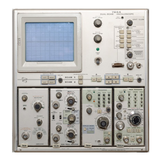
- Page 6 7844 /R78 44 Op erato rs 7844 DUAL- SEA M OSCI LLOS COPE R78 44 OPTiO N 21 DUA L-BE AM OSCIL LOS COPE 1675 -12...
-
Page 7: Operating Instructions
The 7844 / R 7 844 tion to the power source and safety-earth. The operates from a 1 1 5 volt or 230 volt (50 H z to 400 H z ) safety-earth terminal of the plug is directly con... -
Page 8: Operating Temperature
Other colors such as gray, orange and yellow, have nO func tional assignments, but are used as needed to ind icate the A b a i l -type stand is mounted on the bottom of the 7844. ° relationship between controls and/or connectors. -
Page 9: Set-Up I Nformation
Operating Instructions-7844/R7844 Operators Connect the 7844/R7844 to a power source that meets Set-up information for both the standard 7844/R 7844 and the voltage and frequency requirements of the instrument. Option 21 precedes each major section of t h i s F a m i l i ariza... -
Page 10: Front-Panel Controls And Connectors
Operating I nstructions-7844/R7844 Operators 1675-9 Fig. Front-panel controls and connectors. 1·1. 1 ·4... - Page 11 Ground Connector (not marked)-Binding post to establish common ground between associated equipment. 8Current Lo Op{not marked) 7844-Provides 40 mA square-wave current (1 kHz) when the CALIBRATOR switch is set to 40 rnA position. R7844-Provides 40 rnA square·wave current (1 kHz) when optional eurrent loop adapter is connected to the CALlBRA·...
- Page 12 Operating I nstructions-7844/R7844 Operators Rear-panel controls and connectors. Fig. 1-2. 1·6...
-
Page 13: Rear-Panel Controls And Connectors
Operating I nstructions-7844/R7844 Operators REAR-PANEL CONTR O LS AND CONNECTORS MAIN and CLY'D fA GATE) Switch-Selects between main and delay gates from time base unit in A HORIZ compartment. SINGLE SWEEP (A READY) Connector-Output for single-sweep ready signal from time-base unit in A HORiZ compart... -
Page 14: Vertical System And Calibrator
Operating I nstructions-7844/R7844 Operators Vertical System and Calibrator Rotate the G R AT I L L U M control throughout its range and notice that the graticul e l ines are i l l um inated as the Set-up status: control is turned clockwise. -
Page 15: Horizontal System
Operating Instructions-7844!R7844 Operators Right Vertical U n i t Deflection factor, 1 volt! 20. Select d ifferent CA LI B RATO R push buttons labeled division; position, cen 4 V, 0.4 V, 40 mV, and 4 mV and notice those outputs tered in the bottom h a l f can be obtained (CALI B R ATO R output must be termina... -
Page 16: Graticule And Readout Pulsed Operation
Operating I nstructions-7844/R7844 Operators 24. N ote that the B HO R I Z plug·in is displayed on beam Set-up status for the associated equipment: 2. Use the position control of the B H O R IZ plug-in to CAL I B R ATO R change the horizontal location of the d i splayed waveform. -
Page 17: D Eta I L E D Op Erating Information
Crt Display I ntensity Controls FOCUS As desired The 7844 / R 7844 dual·beam oscil l oscope has an I NTENSITY control for each of the two beams. Each of these I NTEN V E RT I CA L M O D E R I G HT SITY controls operate independently. -
Page 18: Trace Ai Ignment
The filter 3. Adjust the FOCUS control so that the top and bottom can be ordered by Tektronix Part 378-0603-00. portions of the waveform are as thin as possible but not elongated. -
Page 19: Beamfinder
Operating I nstructions-7844/R7844 Operators from channel l of each plug-in u n i t is displayed i n the top and by setting the EXT/BEAM 2 GATED switch to BEAM division of the graticule and the readout from channe! 2 i s 2 GAT E D . -
Page 20: Control I Llum Ination
This switch is located o n t h e rear panel o f the 7844 a n d the other accessories which are specifical l y designed for use left side panel of the R7844. -
Page 21: Amplifier Unit Alternate Operation
D u al-trace 7000-series amplifier plug-in units with alternate negative-going signal will increase the trace brightness. Re display modes can be used with the 7844/R7844. Alterna· fer to Table 2- 1 for signal requirements. tion occurs after the completion of each sweep when each... -
Page 22: Output Signals
A permanent record of the crt display can be obtained with with this instrument. an oscilloscope camera system. The instruction manuals for the Tektronix osci l loscope cameras include compl et e instruc tions for obtaining waveform photographs. The following books describe oscilloscope measurement tech niques which can be adapted for use with this instru... -
Page 23: Vertical Amplifier Plug-I N Units
For example, samp sideration when selecting amplifier plug-in units. l i n g systems available for the 7844/R7844 can resolve repe titive signals having less than 1 0 m i l l ivolts of peak amplitude and occu ring in less than 1 nanosecond. -
Page 24: Special Purpose Plug- I N Units
The variety of special-pu rpose plug-in units available al lows measurement, filter design, spectrum surve i l l ance, etc. the 7844/R 7 844 Oscil loscope to be used for many specializ ed applications, The fol l owing is a brief discussion of some of the available special-purpose plug-in units. -
Page 25: Raster Display
Operating Instructions-7844/R7844 Operators Raster Display input to provide intensity modulation of the raster display. With this system, a 7B-series time-base unit can be substi A raster-type display can be used to effectively increase the tuted for the external sawtooth generator and the dual-trace apparent sweep length. -
Page 27: S Pecification
Information given i n this section of the manual applies t o otherwise indicated. Warmup time for given accuracy i s 20 both t h e 7844 a n d R7844 Dual-Beam Oscill oscopes, except m i nutes. as otherwise i ndicated. The R7844 is electrically identical to the 7844, but is adapted for mounting in a standard 1 9- inch rack. - Page 28 Characteristic Plug-in compartment control ling vertical Vertical Display Modes deflection of electron beam BEAM 2 7844/ R 7 844 BEAM 1 Selected by front-panel V E R T I CAL M O D E switch L E FT L E FT...
- Page 29 Specification-7844/R7844 Operators TAB L E 2-1 Icont.1 Electrical Characteristic Performance Requirement Supplemental Information ° Phase Shift Between Vertical and or less from de to at least 50 k H z Horizontal Deflection Systems Bandwidth ( 1 0 div reference) D c to at least 1 M H z Horizontal Centering W i t h i n 0.5 d i v o f graticuie center...
- Page 30 R 7844 40 mA with optional B N C-to-Current Loop Adap- ter, Tektronix part 01 2-034 1 -00. CAL I · B RATOR Switch must b e set t o t h e 4 V position for 40 mA output,...
- Page 31 Specification-7844fR7844 Operators TABLE 2-1 (cont.) Electrical Characteristic Performance Requirement Supplemental Information SIGNAL OUTPUTS A SAWTOOTH Source Time-base unit in A H O R I Z Compart- ment Polarity Positive-going with base- l i n e at within 1 V (into 1 MQ) Output Voltage Rate of Rise Into 50 51...
- Page 32 Specification-7844/R7844 Operators TABLE 2·1 (cont.l Electrical Characteristic Performance Requ irement Supplemental Information Output Voltage I nput 50 Q 0.5 V within 1 0% I nto 1 MrI 1 0 V within 1 0% (up to 1 I1s/div) Risetime Into 50 n...
- Page 33 The three-position switch i s located o n the plug-in units only) left side·panel of the R7844 and on the rear panel of the 7844 S I N G L E SWEEP R ES E T (rear pane l ) BNC connector. Remote single-sweep re-...
- Page 34 Specification-7844!R7844 Operators TABLE 2-' (cont.) Electrical Performance Requirement Supplemental Information Characteristic Maximum Open Circuit Voltage + 1 5 V + 1 5 V, -5 V (dc + peak a c ) Maximum Safe Input Voltage READOUT DISPLAY Mode (front panel)
-
Page 35: System E L Ectr I Ca L Specification
S--Sampling unit T -Sampling time-base u n i t Your Tektronix 7844/R7844 osc i l l oscope system provides exceptional f l ex i bil ity in operation with a wide choice of The third and fourth digits of the plug�jn type num... -
Page 36: 7844/R7844 Oscilloscope System Vertical Specification
Specification-7844/R7844 Operators TABLE 2-2 (cant,) 7844/R7844 Oscilloscope System Vertical Specification Accuracy EXT CAL Amplifier INT CAL Plug"ln Probe Bandwidth Risetime OoC to 500e OoC to 500e Unit IMHz) (ns) (% ) 7 A 1 9 ( 1 0 mV/Div None only) 1 . - Page 37 Safe operating temperature maintained by dc fan. Automatic Ventilation resetting thermal cutout protects instrument from overheat- 20 minutes for rated accuracy Warm-up Time Anodized front panel. 7844�blue vinyl painted aluminum Finish cabinet, R7844-lacquered aluminum cabinet 7844 R7844 Overall D imensions (measured at maximum points) 7.0 inch...
-
Page 38: Stan D A R D Accessor I Es
STAN D A R D ACCESSOR I ES Standard accessories supplied with the 7844 and R 7 844 are given i n the Mechanical Parts List i l l u strations i n the Service man ual. For optional accessories available for use with this instrument, see the Tektronix Products Catalog. - Page 39 NOTE Refer to the Rackmounting section for a dimensional ' drawing of the R7844. " �. 21.6 12.0 54,9 em 30,5 em " 0,76 em � '" • �. • "- CJ CJ "" CJ CJ • " '" ..13.5 12.9 8 = EE = o...
-
Page 41: Rackmounting Instructions
Section 3-7844/R7844 Operators RACKMOUNTING INSTRUCTIONS RACK D I M ENSIONS INTRODUCTION Height The R 7 844 is designed to be installed in a standard 1 9-inch rack with Universal hole spacing. ( I f a rack with other than At l east 7 inches of vertical space are required to mount this Universal h o l e spacing is used, additional mounting holes may instrument in a rack. -
Page 42: S L I De-Out Tracks
Rackmounting I nstructions-7844/R7844 Operators S L I DE-OUT TRACKS The slide-out tracks provided with this instrument permit it NOTE to be extended out of the rack for maintenance and calibra If the rails of the rack are tapped, either driff tion without removing it from the rack. -
Page 43: R Emoving O R Insta L L I Ng T H E Instrum Ent
Rackmounting I nstructions-7844/R7844 Operators R EMOVING O R INSTA L L I NG T H E INSTRUM ENT S L I D E-OUT TRACK L U B R ICATION After initial i nstal lation and adjustment of the sl id-out tracks, The special finish on the sliding surfaces of the tracks pro... - Page 44 Rackmounting I nstructions-7844/R7844 Operators TO I NSTA L L PULL T H E S L i D EOUT TRACK INTERMEDIATE SECTIONS OUT T O T H E F U L L Y EX· T E N D E D POSITION.
-
Page 45: Adjustment Of The Slide-Out Tracks For Smooth Sliding Action
Rackmounting I nstructions-7844/R7844 Operators 1. LOOSEN SCREWS O N BOTH SlOES ILEFT SIDE SHOWN}. 1 . LOOSEN SCREWS ON BOTH SIDES (LEFT S I D E SHOWN). 2. A L LOW SLIDES TO SEEK PROPER WIDTH. 3. CENTER INSTRUMENT. RETIGHTEN SCR EWS. -
Page 46: R7844 Dimensional Drawing
Rackmounting I nstructions-7844/R7844 Operators Fig . 3-6. R7844 dimensional drawing. -
Page 47: Instrument Options
Specification section of this manua l . To meet e m i specifications of instruments e q u i pped with Option 3, a l l unused plug�in compartments must be covered with an emi-shielded blank plug-in panel (Tektronix part 0 1 6-01 55-00). One blank pane! is required for each unused plug-in compartment. -
Page 48: Display Photography
NOTE THE READOUT C I R C U I T BOARD OS LOCA TED ON THE R I G H T SIDE OF THE 7844 AND IN THE TOP R I G H T CENTER O F T H E R7844. -
Page 49: Option I Nformation Locator
Omit Ampl ifier Unit Alternate Oper- ation discussion. Amplifier units, with the alternate mode, can be used without l i mitations in a l l operating modes of the 7844/R7844 Option 21 . E lectrical Specification Vertical specifications, in Table 2-1 include Option 2 1 characteristics. - Page 50 Options-7844/R7844 Operators TABLE 4-1 (cant.) Option I nformation Locator Location of Information Manual Section Instrument Options All Operating instructions, for Option 22, Option 22 continued. (Writing speed are included in this section. Instrument enhancer) Options Electrical ( P l l...
Need help?
Do you have a question about the 7844 and is the answer not in the manual?
Questions and answers