Tektronix 7B53A Instruction Manual
Hide thumbs
Also See for 7B53A:
- Instruction manual (193 pages) ,
- Instruction manual (33 pages) ,
- Instruction manual (13 pages)

Related Manuals for Tektronix 7B53A


Summary of Contents for Tektronix 7B53A
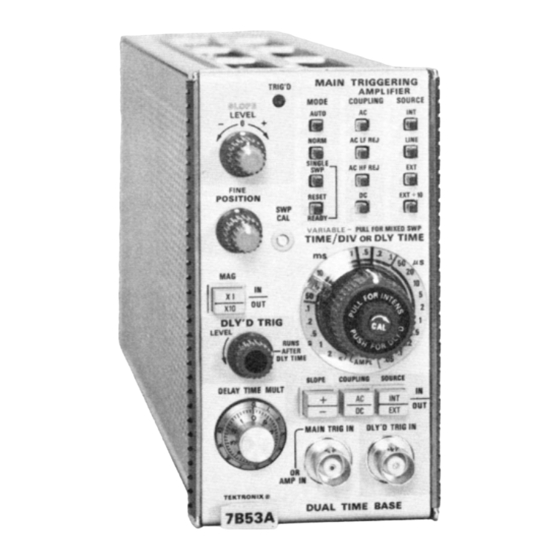
- Page 1 ANUAL SUPPLE TEKTRO N IX 7B53A/7B53AN DUAL TI E BASE OPTION 5 INSTRUCTION ANUAL ektronix, Inc. P.O. Box 500 Beaverton, Oregon 97005 070-1471-00...
- Page 2 WARRAN Y his ektronix product is warranted against defective materialsand workmanship, under normal use, for a period of one year from date of initial shipment. ektronix will repair or replace, at its option, those products determined to be defective within the warranty period and returned, freight prepaid, to a ektronix Service Center.
-
Page 3: Specification
ELEC RICAL CHARAC ERIS ICS This manual insert describes the special features of the 7B53A/7B53AN OPTION 5 plug-in unit which has been Connector Input or Output Signal modified to enable triggering on composite video signals Needs 2 major divisions peak-to- through the use of a Sync Separator circuit. - Page 4 7B53A/7B53AN OP ION 5 OPERATING INSTRUCTIONS Introduction Set the 7B53A/7B53AN OPTION 5 controls as follows: This section describes using the TV Sync Separator Main riggering Amplifier portion of the time base plug-in unit. SLOPE AUTO COUPLING Using the V Sync Separator Plug-In...
-
Page 5: Circuit Description
7B53A/7B53AN OP ION 5 CIRCUIT DESCRIPTION A composite video signal from 0.1 volt peak to peak to 4 The line or horizontal sync pulses are kept from getting volts peak to peak must be supplied to P900 (CO POSITE through Q924 by the RC network of C926 and R926. -
Page 6: Calibration Procedure
H pulses. If R914 is improperly adjusted, the H rate trigger will not be normal during the vertical sync pulse interval. b. Set the 7B53A/7B53AN OPTION 5 controls as follows: 3. Check P932 Waveform Main riggering Amplifier a. - Page 7 Triggering LEVEL control to obtain a triggered display. 9. Check Delayed Internal rigger Operation c. Set the 7B53A/7B53AN OPTION 5 DLY'D TRIG control to RUNS AFTER DLY TI E position. Set the ove the coaxial cable connector from P903 to P904 on...
-
Page 8: Parts List
7B53A/7B53AN OP ION 5 PARTS LIST The following changes should be made to the appropriate parts list for this modified instrument. When ordering replacement parts specify instrument type, serial number, and mod number. Include the circuit number, part number, and description of the desired item. - Page 9 7B53A/7B53AN OP ION 5 Resistors (cont) 330 k 1/4 W 315-0334-00 R909 1/4 W R910 315-0105-00 R912 315-0182-00 1.8 k 1/4 W 315-0182-00 1.8 k 1/4 W R913 311-1226-00 2.5 k R914 R918 315-0112-00 1.1 k 1/4 W R920 315-0303-00...
- Page 11 SYNC SEPARATOR 7B53A/7B53AN OP ION 5 partial TRIGGER PREA P...
- Page 12 MANUAL CHANGE INFORMA ION At Tektronix, we continually strive to keep up with latest electronic developments by adding circuit and component improvements to our instruments as soon as they are developed and tested. Sometimes, due to printing and shipping requirements, we can ’ t get these changes immediately into printed manuals.
- Page 13 Calibration est Equipment Chart This chart compares T 500 product performance to that of older Tektronix equipment. Only those characteristics where significant specification differences occur, are listed. In some cases the new instrument may not be a total functional replacement. Additional support instrumentation may be needed or a change in calibration procedure may be necessary.
Need help?
Do you have a question about the 7B53A and is the answer not in the manual?
Questions and answers