Sign In
Upload
Manuals
Brands
Tektronix Manuals
Test Equipment
R7844
Tektronix R7844 Manuals
Manuals and User Guides for Tektronix R7844. We have
3
Tektronix R7844 manuals available for free PDF download: Instruction Manual
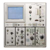
Tektronix R7844 Instruction Manual (436 pages)
DUAL-BEA OSCILLOSCOPE
Brand:
Tektronix
| Category:
Test Equipment
| Size: 59.93 MB
Table of Contents
Table of Contents
3
Introduction
4
System Electrical Specification
18
Standard Accessories
22
R7844 Dimensional Drawing
24
Operating Information
25
Features
25
Controls and Connectors
25
Safety Information
25
Operating Voltage
25
Front-Panel Controls and Connectors
26
Front-Panel Controls, Connectors, and Indicators
27
Rear-Panel Controls and Connectors
28
Rear-Panel Controls and Connectors
29
Installation of Plug-In Units
30
Repackaging for Shipment
30
Plug-In Units
30
Rackmounting
30
Operating Temperature
30
Theory of Operation
31
Block Diagram
31
Description
31
Calibrator and Pulsed Switching
32
Non-Digital Devices
32
Logic Polarity
32
Symbols
32
Logic Fundamentals
32
Detailed Circuit Operation
32
Crossover Mode Switch
33
Detailed Block Diagram of Crossover Mode Switch Circuits
34
Logic Stage
35
Alternate Switching
35
Dedicated Mode Switch (Option 21 Only)
37
Main Interface
37
Input/Output Conditions for Readout Display
37
Logic
38
Detailed Block Diagram of Dedicated Mode
38
Nate Switching
43
Stage
43
Timing Diagram for End of AB Alternate Log
43
Logic
46
Input/Output Conditions for Horizontal Logic
46
Functional Diagram of Beam 1 Z-Axis Logic
46
Functional Diagram of Beam 2 Z-Axis Logic
47
Crossover Vertical Interface
49
Detailed Block Diagram of Trigger Selector
49
Detailed Block Diagram of the Crossover Ver
50
Beam 2 Vertical Amplifier
54
Detailed Block Diagram of the Beam 2 Verti
54
Detailed Block Diagram of the Horizontal in
55
Detailed Block Diagram of the Beam 1 Hori
58
Zontal Amplifier Circuit
59
Detailed Block Diagram of the Beam 2 Hori
59
Beam 2 Horizontal Amplifier
59
Horizontal Interface
59
Detailed Block Diagram of the Beam 2 Hori
60
Zontal Amplifier Circuit
60
Z-Axis Amplifiers
61
CRT Circuit
61
Output Signals
64
Readout System
64
U21 26
69
Display
69
Timer Stage Operation When Display-Skip
70
Idealized Current Waveforms of (A) Row Ana
74
Typical Output Waveforms for Zeros Logic and Memory Stage Operation
77
Converter/Rectifiers
79
Flow Chart for Character Generation by the Readout System
80
Low-Voltage Regulators
81
Enhancer (Option 22)
88
Performance Check Equipment Alternatives
90
Special Calibration Fixtures
90
Test Equipment Required
90
Tektronix Field Service
90
Performance Check Summary
90
Using this Procedure
90
Preliminary Information
90
Performance Check
90
Signal Connections
91
Introduction
97
Index to Performance Check Procedure
97
Perf O Rmance Check Procedure
97
Setup Procedure
98
SN B1 09999-Below; R7844 SN B099999
98
Check Beam 2 Focus Range
99
Check Graticule Illumination Operation
99
Z-Axis and Crt Display
99
Check Beam 1 Edge Focus
100
Check Beam 1 Focus Range
100
Check Beam 1 Geometry
100
Check Beam 2 Edge Focus
100
Check Beam 2 Geometry
100
Check External Beam 1 Z-Axis Operation
101
Check External Beam 2 Z-Axis Operation
101
Calibrator and Output Signals
102
Check Calibrator 1 Khz Repetition Rate
102
Check CALIBRATOR Output Voltage
102
Check CALIBRATOR Risetime, Falltime, and Duty Cycle
102
Check a and BSAWTOOTH Output Signals
103
Check a GATE MAIN/DLY'D Output Signals
103
Check B GATE MAIN/DLY ' D Output Signals
103
Check DC Centering
104
Trigger Selection
104
Check Trigger Gain
105
Check Trigger Response
105
Check Triggering Bandwidth
106
Check Beam 1 Horizontal Amplifier Gain
107
HORIZONTAL SYSTEM (for Instruments 7844 SN B1 1 DODO-Above; R7844 SN B1 00000-Above)
107
Check Beam 1 High-Frequency Timing
108
Check Beam 2 Horizontal Amplifier Gain 4-1
108
Check Beam 1 and Beam 2 Horizontal Amplifier
110
Check Beam 1 and Beam 2 Horizontal Amplifier Gain
110
Check Beam 1 and Beam 2 Horizontal Amplifier Low-Frequency Linearity
110
Horizontal System
110
Low-Frequency Linearity
110
Check Beam 1 High-Frequency Timing
111
Check Beam 2 High-Frequency Timing
111
Check Beam 1 and Beam 2 Vertical Crossover
112
Gain
112
Vertical System
112
Aberrations
113
Check Beam 1 and Beam 2 Vertical Crossover
113
Check Low-Frequency Linearity
113
400 Mhz Gain
114
Check Beam 1 and Beam 2 Vertical Amplifier
114
Check Vertical Channel Isolation
114
Check Vertical Trace Separation Operation
115
Check Readout Modes
116
Readout System
116
Able Autotransformer to Provide the Correct Input
123
Connect the Instrument to a Power Source Tha Meets
123
If the Correct Line Voltage Is Not Available, Use a Vari
123
Note
123
Strument Rear Panel. Refer to the Operating Information Sec
123
The Voltage and Frequency Requirements Marked on the in
123
Tion in this Manual for Operating Voltage Information
123
Allow at Least 20 Minutes Warmup before Proceeding
124
Italized in this Procedure
124
Note
124
Switch (Option 21 Only)
128
Below
129
SN B1 1 0000-Above; R7844 SN B1 00000
132
SN B1 09999-Below; R7844 SN B099999
133
Trig Source )
156
Circuit
171
Advertisement
Tektronix R7844 Instruction Manual (50 pages)
DUAL-BEAM OSCILLOSCOPE
Brand:
Tektronix
| Category:
Test Equipment
| Size: 1.41 MB
Table of Contents
Table of Contents
3
Operating Instructions
7
Featu R es
7
P R E L I M Inary Ope Ration
7
Safety I Nformation '-1
7
Operating Voltage
7
Operating Temperature
8
Operating Position
8
Plug-In Units
8
I Nstallation of Plug-In Units '-2
8
Controls and Connectors
8
Front-Panel Color Coding
8
Fam I L I a R Ization Proc E D U R E
8
Set-Up I Nformation
9
Display Controls '-3
9
Front-Panel Controls and Connectors
10
Rear-Panel Controls and Connectors
13
Vertical System and Calibrator
14
Horizontal System
15
Graticule and Readout Pulsed Operation
16
D Eta I L E D Op Erating Information
17
Crt Display I Ntensity Controls
17
Display Focus
17
Trace AI Ignment
18
Graticule
18
Light Filters
18
Graticule I Llumination
18
Readout Display
18
Beamfinder
19
Control I Llum Ination
20
Calibrator Output '-14
20
Probe Power
20
Horizontal Display Mode Combinations ,.,4
20
Vertical Display Mode Combinations '-14
20
Beam 2 Display Characteristics
20
Amplifier Unit Alternate Operation
21
Trigger Source
21
Intensity Modulation
21
Remote Grat/Readout Single Shot
21
Single Sweep I Nput/Output
21
Output Signals
22
Display Photography
22
Applicati Ons
22
Vertical Amplifier Plug-I N Units
23
Time-Base Plug- I N Units
23
Sampling D Isplays
23
Special Purpose Plug- I N Units
24
Raster Display
25
S Pecification
27
Introduction
27
System E L Ectr I Ca L Specification
35
7844/R7844 Oscilloscope System Vertical Specification
36
7844/R7844 Oscilloscope System Horizontal Specification
36
Stan D a R D Accessor I es
38
Rackmounting Instructions
41
Introduction
41
Instrum Ent D I M Ensi Ons
41
Rack D I M Ensions
41
Height
41
Width
41
Depth
41
S L I De-Out Tracks
42
Mounting P R O C E D U R E
42
R Emoving O R Insta L L I Ng T H E Instrum Ent
43
S L I D E-Out Track L U B R Ication
43
Details for Mounting Stationary Sections
43
Adjustment of the Slide-Out Tracks for Smooth Sliding Action
45
R7844 Dimensional Drawing
46
Instrument Options
47
Controls and Connectors
47
Display Photography
48
Location of Readout Mode Switch on the Readout Circuit Board
48
Option I Nformation Locator
49
Tektronix R7844 Instruction Manual (50 pages)
DUAL-BEAM OSCILLOSCOPE WITH OPTIONS OPERATOR
Brand:
Tektronix
| Category:
Test Equipment
| Size: 1.79 MB
Table of Contents
Table of Contents
3
Features
7
Preliminary Operation
7
Safety Information
7
Operating Voltage
7
Operating Instructions
8
Operating Temperature
8
Operating Position
8
Plug-In Units
8
Installation of Plug-In Units
8
Controls and Connectors
8
Front-Panel Color Coding
8
Familiarization Procedure
8
Set-Up Information
9
Display Controls
9
Horizontal System
17
Detailed Operating Information
17
Crt Display Intensity Controls
17
Display Focus
17
Trace Alignment
18
Graticule
18
Light Filters
18
Graticule Illumination
18
Readout Display
18
Beamfinder
19
Control Hlumination
20
Calibrator Output
20
Probe Power
20
Horizontal Display Mode Combinations
20
Vertical Display Mode Combinations
20
Beam 2 Display Characteristics
20
Amplifier Unit Alternate Operation
21
Trigger Source
21
Intensity Modulation
21
Remote Grat/Readout Single Shot
21
Single Sweep Input/Output
21
Output Signals
22
Display Photography
22
Applications
22
Vertical Amplifier Plug-In Units
23
Time-Base Plug-In Units
23
Sampling Displays
23
Special Purpose Plug-In Units
24
X-Y Operation
24
Raster Display
25
Specification
27
Introduction
27
Electrical
27
System Electrical Specification
35
7844/R7844 Oscilloscope System Vertical Specification
35
7844/R7844 Oscilloscope System Horizontal Specification
36
Special Purpose and Sampling Plug-In Units
36
Environmental
37
Physical
37
Standard Accessories
38
Rackmounting Instructions
41
Introduction
41
Instrument Dimensions
41
Rack Dimensions
41
Height
41
Width
41
Slide-Out Tracks
42
Mounting Procedure
42
Removing or Installing the Instrument
43
Slide-Out Track Lubrication
43
Section4
43
Option Information Locator
49
Instrument Options
50
Advertisement
Advertisement
Related Products
Tektronix R760
Tektronix R7623
Tektronix R7603
Tektronix R7CO3
Tektronix R7623A
Tektronix R7613
Tektronix R7903
Tektronix R3051
Tektronix R485
Tektronix R454A
Tektronix Categories
Test Equipment
Measuring Instruments
Amplifier
Printer
Portable Generator
More Tektronix Manuals
Login
Sign In
OR
Sign in with Facebook
Sign in with Google
Upload manual
Upload from disk
Upload from URL