TESY HPWH 2.1 200 U02 Service Manual
Hide thumbs
Also See for HPWH 2.1 200 U02:
- Instruction for installation and maintenance (155 pages) ,
- User manual (71 pages)

Related Manuals for TESY HPWH 2.1 200 U02


Summary of Contents for TESY HPWH 2.1 200 U02
- Page 1 SERVICE MANUAL v1 – 24/09/2019 HPWH 2.1 200 U02; HPWH 2.1 200 U02 S; HPWH 2.1 260 U02; HPWH 2.1 260 U02 S; Page 1 of 35...
-
Page 2: Table Of Contents
CONTENT: A. Operating principle……………………………………………………3 B. Design overview………………………………………………………4 C. Preliminary check and control…………………………………….…6 D. Access to the heat pump…………………………………………….8 E. Electric wiring diagram and heat pump refrigerant scheme……..9 F. Actions to be taken when error code appears on display………11 G. Intervention procedure………………………………………….….13 H. -
Page 3: Operating Principle
A. OPERATING PRINCIPLE The equipment is capable of producing domestic hot water mainly by using heat pump technology. A heat pump is capable of transferring thermal energy from a low temperature source to another with a higher temperature and vice versa. The equipment uses circuit consisting of a compressor, an evaporator, a condenser and a throttle valve;... -
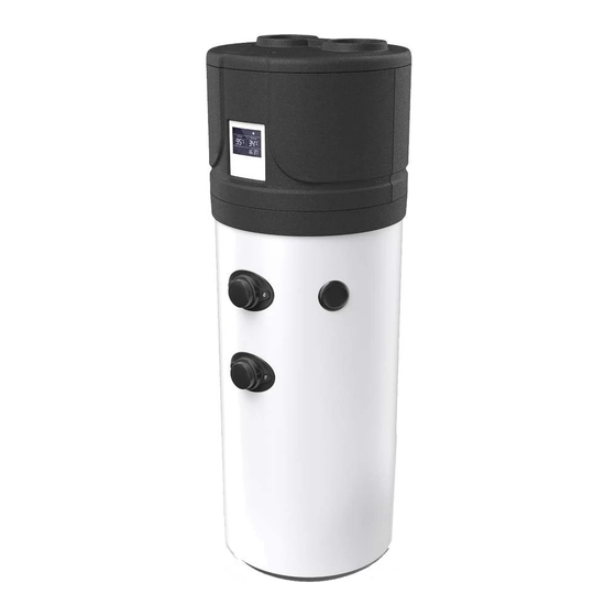
Page 4: Design Overview
B. DESIGN OVERVIEW Heat pump. Control panel. External PVC jacket. Enameled storage tank Upper storage tank probe. “T3” Lower storage tank probe. “T2” Refrigerant recharge needles. Ambient air recirculation fan. Electronically regulated expansion valve valve. High-efficiency finned evaporator. Air inlet (∅ 160 mm). Air outlet (∅... - Page 5 Page 5 of 35...
-
Page 6: Preliminary Check And Control
C. PRELIMINARY CHEK AND CONTROL Make sure that: Water flow missing? Water supply network is in service Opening the hot water tap, it does Incoming water pressure is adequate not come out anything Inlet water valve is open (no flow). Check if there is any obstruction in the circuit upstream the product (hot water outlet) Make sure that: Hot water missing? - Page 7 Make sure that: Verify if the dripping originates: • From one of the hydraulic connections (not intact) Water loss? • From the overpressure protection device (safety valve). • Check if it is working properly. The product is dripping. • From inside the product Check if the condensate drain is connected properly and/or if it is obstructed.
-
Page 8: Access To The Heat Pump
D. ACCSES TO THE HEAT PUMP – OPENING OF THE EXTERNAL CASE. Unwind the screws No40 (M6x60; DIN564) Pull the upper panel No32 in upper direction Pull the Front 34 and Back 33 panels in upper direction (~3cm) and then in front direction Page 8 of 35... -
Page 9: Electric Wiring Diagram And Heat Pump Refrigerant Scheme
E. ELECTRIC WIRING DIAGRAM AND HEAT PUMP REFRIGERANT SCHEME. Page 9 of 35... - Page 10 Page 10 of 35...
-
Page 11: Actions To Be Taken When Error Code Appears On Display
F. ACTIONS TO BE TAKEN WHEN ERROR CODE APPEARS ON DISPLAY Protection/ Malfunction Error code LED indicator Possible reasons Corrective actions Procedure Standby Dark Normal running Bright ☆● Lower tank water temp. sensor 1) The sensor open circuit 1) Check the sensor connection 1) Procedure 2 failure 2) The sensor short circuit... - Page 12 3) The electronic expansion valve 3) Check and replace the electronic 3) Procedure 8 assembly blocked expansion valve assembly 4) Too much refrigerant 4) Discharge some refrigerant 4) Procedure 9 5) The switch damaged 5) Replace a high-pressure switch 5) Procedure 10 6) The uncompressed gas is in 6) Discharge and then recharge the 6) Procedure 9...
-
Page 13: Intervention Procedure
G. INTERVENTION PROCEDURE. Procedure 1 CHANGING THE MAIN PCB PSB code: G0010018; PSB model: HY473024 Screw driver PH2; Pliers Tools: Fig: pr.1.1. Fig: pr.1.2. Risk of electric shock! Disconnect the HPWH from the main electric supply!!! Switch off the HPWH Disconnect the unit from main electricity supply Unscrew four screws No: 1;... - Page 14 Procedure 2 CHECK AND CHANGE OF LOWER TANK TEMPERATURE SENSOR T2 NTC thermosensor code: G0030153; NTC thermosensor model: 5K/L1200T Screw driver PH2; Pliers Tools: Fig: pr.2.1: Risk of electric shock! Disconnect the HPWH from the main electric supply!!! Switch off the HPWH Open the PCB box as per procedure 1.
- Page 15 CHECK AND CHANGE OF UPPER TANK TEMPERATURE SENSOR – T3 Procedure 3 NTC thermosensor code: G0030153; NTC thermosensor model: 5K/L1200T Screw driver PH2; Pliers Tools: Fig: pr.3.1: Risk of electric shock! Disconnect the HPWH from the main electric supply!!! Switch off the HPWH Open the PCB box as per procedure 1.
- Page 16 Procedure 5 CHECK AND CHANGE OF RETURN GAS TEMPERATURE SENSOR NTC thermosensor code: G0030153; NTC thermosensor model: 5K/L1200T Screw driver PH2; Pliers Tools: Risk of electric shock! Fig: pr.5.1: Disconnect the HPWH from the main electric supply Switch off the HPWH Open the PCB box as per procedure 1.
- Page 17 Procedure 6 Check and change of ambient air temperature sensor NTC thermosensor code: G0030152; NTC thermosensor model: 5K/L1200S Screw driver PH2; Pliers Tools: Fig: pr.6.1: Risk of electric shock! Disconnect the HPWH from the main electric supply Switch off the HPWH Ambient air Open the PCB box as per procedure 1.
- Page 18 Procedure 8 CHECK AND REPLACE THE ELECTRONIC EXPANSION VALVE ASSEMBLY Electronically regulated expansion valve ERV; Code: C0050014; Model: DPF(Q)1.3C-01(1-RK Screw driver PH2; Pliers; spanner S10; S12; S13; Cutting tool for copper pipe; burner for brazing; brazing rods; vacuum pump; recovery unit; bottles for refrigerant; scales; leak detectors; Tools: pressure hoses;...
- Page 19 Procedure 9 VACUUMING, CHARGING AND DISCHARGING REFRIGERANT Tools: Screw driver PH2; Pliers; spanner S10; S12; S13; Cutting tool for copper pipe; burner for brazing; brazing rods; vacuum pump; recovery unit; bottles with refrigerant; scales; leak detectors; pressure hoses; Instrument for parameters check Fig: pr.9.1: Risk of electric shock! Disconnect the HPWH from the main electric supply!
- Page 20 CHARGING WITH REFRIGERANT R134a 15) Unscrew the protective cap of low-pressure probe (Fig pr.9.1) Fig: pr.9.6: Fig: pr.9.7: 16) Connect the high-pressure hose, equipped in both ends with taps to the probe and to the recovery machine. By the same way connect recovery machine to the filled bottle for R134a (Fig pr.9.6).
- Page 21 Procedure 10 10. REPLACE A HIGH/LOW-PRESSURE SWITCH Low pressure switch: Code: C0080003; Model: DYKG-0.02/0.1 High pressure switch: Code: C0080006; Model: GYKG-2.5/1.8 Screw driver PH2; Pliers; spanner S10; S12; S13; Cutting tool for copper pipe; burner for brazing; brazing rods; vacuum pump; recovery unit; bottles for refrigerant; scales; leak detectors; Tools: pressure hoses;...
- Page 22 Procedure 11 11. CHECK / REPLACE THE FAN Fan motor: Code: D0040012; Model: YDK25-4D(YDK20-4F1) Screw driver PH2 & PH 3; Pliers; Spanners S10; S12; S13 Tools: Fig: pr.11.1: Fig: pr.11.2: Risk of electric shock! Disconnect the HPWH from the main electric supply INITIAL CHEK OF VENTILATOR: CAPACITOR Clean the ducts and the filter (in some models)
- Page 23 Fig: pr.11.7: Screws No2 11 pieces Screws No3 Screws No3 4 pieces 4 pieces Screws No3 Screws No3 4 pieces 4 pieces Fig: pr.11.6: Fig: pr.11.7 Page 23 of 35...
- Page 24 Procedure 12 12. REPLACE THE THERMAL SWITCH Thermal switch 80 C; Code: G0030162; Model: BW9700 (80 Screw driver PH2 & PH3; Pliers Tools: Fig: pr.12.1 Fig: pr.12.4 Metric screw Risk of electric shock! Disconnect the HPWH from the main electric supply Switch off the HPWH Open the PCB box as per procedure 1.
- Page 25 Procedure 13 REPLACE THE 4-WAY VALVE 4-way valve: Code: C0050001; Model: STF-3*127-952-R410A Screw driver PH2; Pliers; spanner S6; S10; S12; S13; Cutting tool for copper pipe; burner for brazing; brazing rods; vacuum pump; recovery unit; bottles for refrigerant; scales; leak Tools: detectors;...
- Page 26 Procedure 14 ELECTRIC HEATING ELEMENT CHECK / REPLACEMENT Limit control thermostat 90 C: Code: 702262 El. Heat. element 1500W 230V: Code: 106400 Gascket G1½; Ø61х48.5х3: Code: 106410 Screw driver PH2; PH3 Pliers; Socket spanner S60; El. Multimeter Tools: Fig: pr.14.1: Risk of electric shock! Disconnect the HPWH from the main electric supply Reset button...
- Page 27 Procedure 15 COMPRESSOR CHECK / REPLACE Compressor: Code: D0020030; Model: WHP01900BSV-H8JU Compressor capacitor: Code: G0050012; Model: CBB65-15UF Screw driver PH2 & PH3; Pliers; El= multimeter; Spanner S8; S10 Tools: Fig: pr.15.1: Risk of electric shock! Disconnect the HPWH from the main electric supply Risk of injuries due to refrigerant vapors! Discharge refrigerant! Use special protective gloves for refrigerant and eyeglasses!
- Page 28 Fig: pr.15.4: Fig: pr.15.3: Fig: pr.15.6: Fig: pr.15.5: Ground connection Page 28 of 35...
- Page 29 Procedure 16 REPLACE THE CONTROL DISPLAY Control display ; Code: G0020045; Model: HY473091 Screw driver PH1 & PH2; Tools: Fig: pr.16.1: Risk of electric shock! Disconnect the HPWH from the main electric supply!!! Switch off the HPWH Disconnect the unit from main electricity supply Screws No1 On the back side of the front panel, unscrew four screws No: 1;...
- Page 30 Procedure 17 Replacement of transformer Transformer: Code: G0040001; Model: BYQ-800MA Screw driver PH2; Pliers Tools: Risk of electric shock! Disconnect the HPWH from the main electric supply!!! Transformer Switch off the HPWH Disconnect the unit from main electricity supply Open the front cover of PCB box as per procedure 1 Disconnect all cables and wirings of the Transformer connected to the PCB.
-
Page 31: Full List Of Controller's Parameters
H. FULL LIST OF CONTROLLER’S PARAMETERS. Visibility: Param. U=user Description Range Default Remarks I=installer=29 M=manufacturer=76 Adjusting parameters: 10 ~ 70°C Tank water setting temp. Adjust Adjustable 2 ~ 15°C 5°C Water temp difference Adjustable 10 ~ 90°C E-heater off tank water temp 65°C Adjustable E-heater delay time... - Page 32 Disinfection period 1~30 days 7 days Adjustable EXV open step during defrosting 10 ~ 47 Adjustable EXV delay time 3 ~ 30 21; N*10 sec. Adjustable Low pressure switch detects temp -10~25 Adjustable Delay detects time of low-pressure switch 2min~20min 5min after compressor start Temp to change 4-way change working way...
-
Page 33: Evaporating Pressure
I. EVAPORATING PRESSURE Working diagram - Inlet air temperature; 2 Working diagram - Inlet air temperature; 7 4.50 4.50 4.30 4.30 4.10 4.10 3.90 3.90 3.70 3.70 3.50 3.50 3.30 3.30 3.10 3.10 Defrosting possible!!! 2.90 2.90 2.70 2.70 2.50 2.50 10.0 15.0... -
Page 34: Tools And Equipment
2.90 Gas pressure of R134a acc. to its temperature 2.80 2.70 2.60 2.50 2.40 2.30 2.20 2.10 2.00 1.90 1.80 1.70 1.60 1.50 10.0 15.0 20.0 25.0 30.0 35.0 40.0 45.0 50.0 55.0 Water tank temperature; gas temperature; Air 2oC Air 7oC Air 14oC Air 20oC... - Page 35 • Vacuuming Vacuum pump • Charging / Discharging refrigerant Recovery machine • Scales • High pressure hoses refrigerant • Refrigerant bottles full/empty • Special measuring instruments Multifunctioning tool for heat pump and air conditioning measurements • El. Multimeter • Manometers Page 35 of 35...
Need help?
Do you have a question about the HPWH 2.1 200 U02 and is the answer not in the manual?
Questions and answers