
Related Manuals for Comco 921 Series

Summary of Contents for Comco 921 Series
- Page 1 Series Installation and Operator Manual 500628 Rev. A ComCo Systems Inc. | 800.533.3794 www.comcosystems.com...
- Page 2 This publication contains materials protected by copyright. No part of this publication may be reproduced in any form or used as the basis for the sale or manufacture of apparatus without prior written consent by ComCo Systems. ©2013 ComCo Systems INC All rights reserved Some of the materials and applications described in this publication may be protected under one or more of the following US patents: DES272076, 4180354, 4971481, 4984939, 5584613, 6039510, or other Patents Pending.
-
Page 3: Table Of Contents
Theory of Operation pg. 14 Installation & Maintenance pg. 16 System Setup and Installation Field Wiring Diagram Replacement Parts Help Desk Information pg. 29 Return Materials Authorization Procedure Contact Information ComCo Systems Inc. | 800.533.3794 | www.comcosystems.com 500628 Rev A... -
Page 4: System Features
Manual operated door unit, which is suspended from the ceiling, typically over countertop. Dual Pack UL Blowers 200281-3 Features: 2 Power Cords 2 115Vac/15A 2 Blowers for pressure 2 Blowers for vacuum ComCo Systems Inc. | 800.533.3794 | www.comcosystems.com 500628 Rev. A... - Page 5 Series Teller Unit TU-921-200430-1 Model: ComCo Systems Inc. | 800.533.3794 | www.comcosystems.com 500628 Rev A...
-
Page 6: Operation
Opening the door will cancel operation. To resume operation close door and press RECALL or SEND. Please note the reference guide in Fig. 1.0. **NOTE: Door Close Light next to the manual door handle MUST be ON to function properly ComCo Systems Inc. | 800.533.3794 | www.comcosystems.com 500628 Rev. A... -
Page 7: Operations
RECALL Recalls a carrier from the customer unit. The teller unit door must be closed in order to recall a carrier from the customer unit. ComCo Systems Inc. | 800.533.3794 | www.comcosystems.com 500628 Rev A... -
Page 8: Specification
Item Measurements Value Teller Unit Nominal Voltage 24 VAC From Blower (TU-921-200430-1) Current (max) 1 Amp System Controller (P/N: 200155K) See Appendix A For System Settings OPEN SEND CLOSE RECALL ComCo Systems Inc. | 800.533.3794 | www.comcosystems.com 500628 Rev. A... -
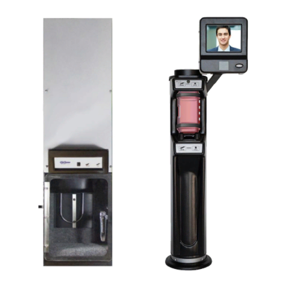
Page 9: Customer Unit
Series Customer Unit CU-921-201280 Model: ComCo Systems Inc. | 800.533.3794 | www.comcosystems.com 500628 Rev A... -
Page 10: Operations
Machine & Switch Operating Instructions SEND Sends carrier to Teller Unit. CALL Generates audible tone at the Pharmacy/Teller Center when depressed. Top Switch Keypad (P/N: 200573-2) Bottom Switch Keypad (P/N: 200574-2) ComCo Systems Inc. | 800.533.3794 | www.comcosystems.com 500628 Rev. A... -
Page 11: Specification
Dimensional & Electrical Specifications Item Measurements Value Customer Video Module Nominal Voltage 12 VDC (CVM-2000-200903-10) Current (max) 3.5 Amps 1520 Lane Station Nominal Voltage 12 VDC (600651) Current (max) 1.5 Amps ComCo Systems Inc. | 800.533.3794 | www.comcosystems.com 500628 Rev A... -
Page 12: Blower
Series Dual Pack Blower 200281-3 Model: ComCo Systems Inc. | 800.533.3794 | www.comcosystems.com 500628 Rev. A... - Page 13 2-115 VAC 0.5 A Resettable Fuse 2-115 VAC 1.5 A Resettable Fuse Class 2 Field Wiring Use ¼” minimum hardware to mount unit in place. For mounting location see cut sheets for job site. ComCo Systems Inc. | 800.533.3794 | www.comcosystems.com 500628 Rev A...
-
Page 14: Specification
The contents of the carrier must be fully within the carrier and not caught between edges. Multiple transmissions should be used if a load is too large to fit within the single carrier. ComCo Systems Inc. | 800.533.3794 | www.comcosystems.com 500628 Rev. A... -
Page 15: Theory Of Operation
7. Carrier passes Deceleration Switch Tube over Customer Unit 8. Pressure blower deactivates 9. Carrier decelerates due to Solenoid engaging 10. Solenoid timer waits for Carrier to land. 11. Send cycle ends; System is now in ready state ComCo Systems Inc. | 800.533.3794 | www.comcosystems.com 500628 Rev A... - Page 16 8. Carrier is decelerated by pressure ahead of carrier (valve in Teller Check Valve blocks pressure from Teller Unit) 9. Carrier arrives at Teller Unit. 10. Cycle timer times out 11. Recall cycle ends – system is now in ready state ComCo Systems Inc. | 800.533.3794 | www.comcosystems.com 500628 Rev. A...
-
Page 17: Installation & Maintenance
Series Installation Installation Cut Sheets NOTE: ComCo Systems Inc. | 800.533.3794 | www.comcosystems.com 500628 Rev A... - Page 18 Series Installation Installation Cut Sheets NOTE: ComCo Systems Inc. | 800.533.3794 | www.comcosystems.com 500628 Rev. A...
- Page 19 Series Installation Installation Cut Sheets NOTE: ComCo Systems Inc. | 800.533.3794 | www.comcosystems.com 500628 Rev A...
- Page 20 Series Installation Installation Cut Sheets NOTE: ComCo Systems Inc. | 800.533.3794 | www.comcosystems.com 500628 Rev. A...
-
Page 21: Field Wiring Diagram
Series Installation Installation Field Wiring Diagram (D/N: 500618) NOTE: Deceleration switches MUST be wired in Parallel ComCo Systems Inc. | 800.533.3794 | www.comcosystems.com 500628 Rev A... - Page 22 Series Installation Installation Field Wiring Diagram (D/N: 500624) NOTE: Deceleration switches MUST be wired in Parallel ComCo Systems Inc. | 800.533.3794 | www.comcosystems.com 500628 Rev. A...
- Page 23 Series Installation Installation Field Wiring Diagram (D/N: 500619) NOTE: Deceleration switches MUST be wired in Parallel ComCo Systems Inc. | 800.533.3794 | www.comcosystems.com 500628 Rev A...
- Page 24 Series Installation Installation Control/Audio Field Wiring Diagram (D/N: 500073) NOTE: Refer to Audio Authority Manual for Audio Installation ComCo Systems Inc. | 800.533.3794 | www.comcosystems.com 500628 Rev. A...
- Page 25 Series Installation System Riser Diagram & Options Parts Descriptions: ComCo Systems Inc. | 800.533.3794 | www.comcosystems.com 500628 Rev A...
- Page 26 Carriers should be replaced regularly – usually every 3-6 months, depending on usage. Customer Unit & Teller The carrier deceleration switches are required for proper operation. If they are inoperable, the carrier will land hard at the customer unit. ComCo Systems Inc. | 800.533.3794 | www.comcosystems.com 500628 Rev. A...
-
Page 27: Replacement Parts
Membrane Valve Assembly for Check Valve 200663 QT-2010 Conversion Description Part Number Usage per Lane Keypad 201078-1 Power Switch Assembly 200391-2 Keypad Interface Harness 200190 Control Box 200703-4 Membrane Valve for Check Valve 400116-1 ComCo Systems Inc. | 800.533.3794 | www.comcosystems.com 500628 Rev A... - Page 28 604435 10 Amp Circuit Breaker 604412 Solenoid Assembly 200282 Carriers Description Part Number Usage per Lane 4x7 Hybrid Carrier 400215-8 Misc. Description Part Number Usage per Lane Deceleration Switch 200599 ComCo Systems Inc. | 800.533.3794 | www.comcosystems.com 500628 Rev. A...
- Page 29 Series Appendix A ComCo Systems Inc. | 800.533.3794 | www.comcosystems.com 500628 Rev A...
-
Page 30: Help Desk Information
Lake Dallas, TX. 75065 RMA# XXXX All RMAs will be processed in the order they are received. ComCo Systems will not accept any returns that do not have an RMA# assigned. To check on the status of an RMA call our Customer Service Representatives with your RMA#. - Page 31 • Parts Orders parts@comcosystems.com 800.533.3794 Option 2 • Equipment and System Sales sales@comcosystems.com 800.533.3794 Option 3 • Project Management 800.533.3794 Option 4 • Accounting accounting@comcosystems.com 800.533.3794 Option 5 https://www.facebook.com/ComcoSystems https://twitter.com/comcosystems ComCo Systems Inc. | 800.533.3794 | www.comcosystems.com 500628 Rev A...
Need help?
Do you have a question about the 921 Series and is the answer not in the manual?
Questions and answers