Table of Contents
Advertisement
Quick Links
TM
SMART EMS
SERVICE MANUAL
PRODUCT DESCRIPTION
TM
The
SMART EMS
is a completely self-contained120 volt power distribution and energy management system
intended to be used in recreational vehicles. It is housed in a sheet metal enclosure with removable front panel. It
provides circuit protection for all the 120 VAC loads in the RV and a system of energy management to minimize the
over-loading and tripping of circuit breakers.
TM
Circuit Breakers
- the
SMART EMS
offers slots for four single or dual, standard 120 volt circuit breakers. One of
these breakers must be a 30 Amp unit that acts as a main input protection for the remainder of the branch breakers
(up to 7).
TM
Energy Management
- the
SMART EMS
offers control of up to four, 120 volt operated appliances to help keep the
total 120 volt current draw to less than 30 Amps. These appliances may be any type load, but are typically heavier
loads, those whose use can be "postponed" until a time when current is available for their use.
1485 Jacobs Rd.
Intellitec
Deland, FL 32724
386.738.7307
www.intellitec.com
P/N 53-00549-100 Rev. C 032619
Advertisement
Table of Contents

Subscribe to Our Youtube Channel
Related Manuals for Intellitec SMART EMS


Summary of Contents for Intellitec SMART EMS
- Page 1 SMART EMS SERVICE MANUAL PRODUCT DESCRIPTION SMART EMS is a completely self-contained120 volt power distribution and energy management system intended to be used in recreational vehicles. It is housed in a sheet metal enclosure with removable front panel. It provides circuit protection for all the 120 VAC loads in the RV and a system of energy management to minimize the over-loading and tripping of circuit breakers.
-
Page 2: Circuit Protection
SERVICE MANUAL CAUTION The SMART EMS is a centralized power switching, fusing, and distribution center. Power from the 120 volt power source is fed into the box. The potential of lethal electrical shock is present in this box. Inadvertent only shorts at this box could result in damage and/or injury. -
Page 3: Operation
SMART EMS SERVICE MANUAL OPERATION In operation, when the 120 VAC and 12 VDC are applied, the system will energize the relays, one at a time. The three AC relays and two DC relays will move from the N/O to N/C position. -
Page 4: Installation
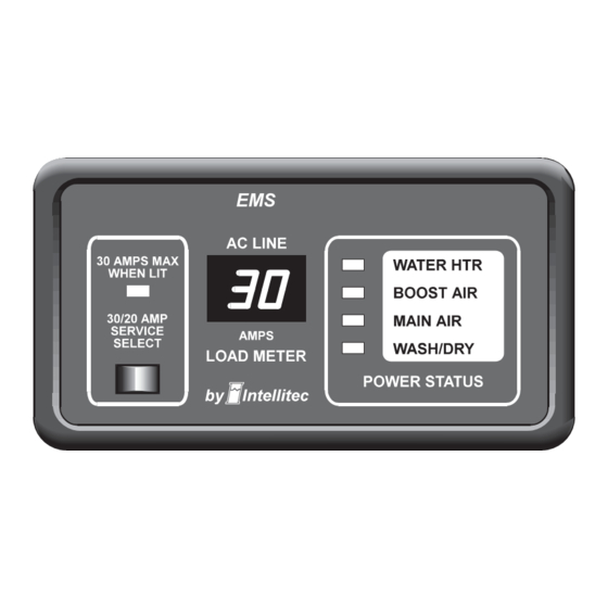
SMART EMS SERVICE MANUAL The Service Select button allows the current threshold to be set to either 30 Amps or 20 Amps, to match the incoming service. If the pictured adaptor is used on the incoming service, press the service select button to select the 20 Amp mode. - Page 5 SMART EMS SERVICE MANUAL LOAD NAME Load (First to shed at top) Type Next, looking across the other eight columns, find the one that matches the "Load Type" column you just filled in. This column is then the function of the EMS.
- Page 6 SMART EMS SERVICE MANUAL 1485 Jacobs Rd. Intellitec Deland, FL 32724 386.738.7307 www.intellitec.com P/N 53-00549-100 Rev. C 032619...
- Page 7 SMART EMS SERVICE MANUAL PLACEMENT The EMS should be installed in a convenient location where it can get air circulation to keep it from over heating. There should be a minimum of 7" of depth behind the mounting surface to provide enough room for the box and wiring.
- Page 8 SMART EMS SERVICE MANUAL The 12 VDC voltage connections are made through the 8 pin Mate-N-Lok plug on the low voltage side of the control module. The connections are as follows: Function + 12 Volts Ground Relay 4 Normally Open...
-
Page 9: Performance Test
SMART EMS SERVICE MANUAL PERFORMANCE TEST The system is now ready for testing. Hi-POT TEST At the installers preference, to assure there are no potential shorts, a Hi-Pot test can be performed on the installation. To do this, +12 volts must be applied to the system. A jumper wire must be installed to tie the two pins of the "Hi-Pot Test" plug, J1, to turn the system on without the presence of 120 volt power. - Page 10 SMART EMS SERVICE MANUAL The replacement circuit breakers must be of the same type and rating. FUSE - 3 Amp ATO type, for EMS circuitry only. DO NOT replace with a fuse of higher rating. This could result in severe damage to the circuitry or create a possible fire hazard.
-
Page 11: Troubleshooting
SMART EMS SERVICE MANUAL Trouble Shooting If the following problems occur, proceed with their analysis in the order in which the steps are listed. No 120 volt appliances working. A. Check incoming power source. 1. Make sure the shore power cord is plugged into the outlet. - Page 12 SMART EMS SERVICE MANUAL Trouble Shooting Air conditioner doesn't work. A. Check thermostat wiring and settings. B. Check air conditioner VI. Shedding order incorrect. A. Check jumper setting per Figure on page 5. B. Check relay wiring per Figure on page 5.
- Page 13 SMART EMS SERVICE MANUAL 1485 Jacobs Rd. Intellitec Deland, FL 32724 386.738.7307 www.intellitec.com P/N 53-00549-100 Rev. C 032619...
- Page 14 SMART EMS SERVICE MANUAL 1485 Jacobs Rd. Intellitec Deland, FL 32724 386.738.7307 www.intellitec.com P/N 53-00549-100 Rev. C 032619...
- Page 15 SMART EMS SERVICE MANUAL 1485 Jacobs Rd. Intellitec Deland, FL 32724 386.738.7307 www.intellitec.com P/N 53-00549-100 Rev. C 032619...
- Page 16 SMART EMS SERVICE MANUAL 1485 Jacobs Rd. Intellitec Deland, FL 32724 386.738.7307 www.intellitec.com P/N 53-00549-100 Rev. C 032619...
Need help?
Do you have a question about the SMART EMS and is the answer not in the manual?
Questions and answers