
Subscribe to Our Youtube Channel
Related Manuals for Intellitec iConnex


Summary of Contents for Intellitec iConnex
- Page 1 USER MANUAL V2.0 08/10/21 DATA 11 10R05/01 11558 Technical Helpline +44 (0) 151 482 8970 www.intellitecmv.com 11 10R05/01 11558 Page 1...
- Page 2 Intellitec MV Ltd reserves the right to update this document (User’s Manual) without notification at any time. You will find the latest documents for our products on our website: www.intellitecmv.com...
-
Page 3: Specification
Input Voltage (Volts DC) 9-32 Max Input Current (A) Standby Current Consumption (mA) 29 mA 19 mA Sleepmode Current Consumption (mA) IP Rating of iConnex module Ip20 Weight (g) 367g Dimensions L x W x D (mm) 135x165x49 INPUTS OUTPUTS... -
Page 4: Installation
INSTALLATION Schematic: Page 4... - Page 5 INSTALLATION Connector Plug Wiring: Automotive rated 1mm cable must be used with the Molex connectors: Connector Description Manufacturers Part Number Power Connection 10/6 CTT (Copper Tube Terminal) 531021 Keypad Connector Molex 6-Way Female Housing 0469920610 Cable Entry View 1. 0V (Ground) to keypad only. 2.
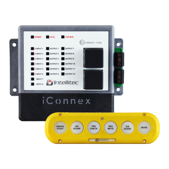
- Page 6 DIAGNOSTIC DISPLAY 1 DATA POWER The POWER diagnostic LED illuminates green when power is active at the module. It will illuminate red during fault conditions. DATA The KEYPAD diagnostic LED illuminates green when a keypad is connected to the module. It will flash blue when any button is pressed on the keypad to show communications are present.
- Page 7 DISPLAY 2 DATA PROGRAMMING When programming the iConnex, the LEDs on the diagnostic display will change function to show the status of the programming operation. The column on output LEDs 1-6 will illuminate green with a single red LED that flashes vertically to indicate programming mode is active.
- Page 8 GUI is the utility used to write and upload programs to the module. It can be downloaded, along with programming device drivers, from our website: www.intellitecmv.com/pages/downloads Page 8...
- Page 9 Addressing The module can be put into ‘slave’ mode by turning the dial to 1,2,3 or 4. A power cycle is required to activate these modes. See below table for active modes: Master Module Slave Module 1 Slave Module 2 Slave Module 3 Slave Module 4 Reserved For Future Use...
- Page 10 PROGRAMMING The module can be programmed using the new USB-B connector. The module will automatically enter programming mode when the GUI attempts to program the module via this USB connection. USB-B Page 10...
- Page 11 Resistor Jumpers The module has two CAN-Bus data line connections. If the line demands a termination resistor at the iConnex module location, these can be enabled by selecting the jumper position accordingly. iConnex Data CAN-Bus Termination Resistor Jumper External CAN-Bus Termination Resistor Jumper...
- Page 12 SWITCH SWITCH ......To change the address of an iConnex keypad, start with the keypad powered off. Press and hold switch 1 and power up the keypad (through the module). All buttons will go . You can let go of the switches at this point. (At this point, the LEDs will turn off.
- Page 13 SWITCH SWITCH The iConnex system installation can be expanded to up to 5 modules and 5 keypads. That's a total of 40 inputs, 60 outputs and 30 keypad buttons! The modules and keypads communicate on the same data network by wiring the 'keypad connector' wiring in parallel.
- Page 14 They also have a programmable RGB status LED in the centre. All keypads aremade from robust, hard-wearing silicon. All iConnex keypads are IP66 and can be mounted externally. Customer logos can be requested on order for the dome inserts on the keypads for a small additional cost.
- Page 15 KEYPAD OLED Series OLED DIN ENG-166-0000 OLED X12 ENG-199-0000 Page 15...
-
Page 16: Temperature Sensor
The iConnex temperature sensor is an optional extra component, enhancing the PLC capability and user experience. Easy to wire into the iConnex system using the 3-wire colour code as shown in the above diagram. The temperature sensor connects to the auxiliary connector on the iConnex module.
Need help?
Do you have a question about the iConnex and is the answer not in the manual?
Questions and answers