Garmin GPS II Plus Owner's Manual & Reference
Garmin gps ii plus: user guide
Hide thumbs
Also See for GPS II Plus:
- Owner's manual (108 pages) ,
- Quick reference manual (2 pages) ,
- Specifications (2 pages)
Table of Contents
Advertisement
Advertisement
Table of Contents

Related Manuals for Garmin GPS II Plus


Summary of Contents for Garmin GPS II Plus
- Page 2 GARMIN. Information in this document is subject to change without notice. GARMIN reserves the right to change or improve its products and to make changes in the content without obligation to notify any person or organization of such changes.
-
Page 3: Thank You
Section Three (Reference) provides details about the advanced features and operations of the GPS II Before getting started with your GPS, check to see that your GARMIN GPS II + package includes the following items. If you are missing any parts, please contact your dealer immediately. - Page 4 NAVigation AID (NAVAID), any NAVAID can be misused or misinterpreted and, therefore, become unsafe. For vehicular applications, it’s the sole responsibility of the owner/operator of the GPS II GPS unit so that it will not cause damage or personal injury in the event of an accident. Do not mount the GPS II over airbag panels or in a place where the driver or passengers are likely to have an impact with it in an accident or collision.
- Page 5 (2) this device must accept any interference received, including interference that may cause undesired operation. The GPS II does not contain any user-serviceable parts. Repairs should only be made by an authorized GARMIN service center. Unauthorized repairs or modifications could void your warranty and your authority to operate this...
-
Page 6: Table Of Contents
SECTION ONE What is GPS? ......1 Satellite Acquisition .....2 Battery Installation . - Page 7 What is GPS? GPS is a system of 24 satellites which circle the earth twice a day in a very pre- cise orbit and transmit information to earth. The GPS II least three of these satellites to calculate your position and track your movement.
-
Page 8: Satellite Acquisition
In a nutshell, the GPS receiver’s view of the sky will generally deter- mine how fast you get a position fix—or if you get a fix at all. GPSsignals are rela- tively weak and do not travel through rocks, buildings, people, metal, or heavy tree cover, so remember to keep a clear view of the sky at all times for best performance. -
Page 9: Battery Installation
You may find that the battery life varies in different conditions and that lithium batteries provide longer life in colder conditions. When replacing the GPS II ’s batteries, observe the polarity markings engraved in the plastic case. An internal 10-year lithium battery will retain your data while you’re changing batteries. -
Page 10: Screen Orientation
Antenna Function Keys Power Key (red) Rocker Keypad LCD Display To change the screen orientation, press and Battery Door hold the page key. - Page 11 (POWER)— Red key turns the unit on and off, and controls three levels of screen backlighting intensity. (PAGE)— Scrolls main pages in sequence and returns display from a submenu page to a main page. Press and hold this key to change screen orientation. (MARK)—...
- Page 12 Screen Orientation zontal mounting position in a vehicle or on a bike to a vertical orientation for hand- held outdoor use, such as hunting or hiking. The GPS to function identically, no matter if you’re using the unit vertically (Fig. 6a) or horizontally (Fig. 6b).
- Page 13 Initializing Your GPS II To initialize the GPS II , take the receiver outside and find an open area where the antenna has a clear view of the sky. You may either hold the receiver at a com- fortable height with the external antenna pointing up (Fig. 7a), or mount the receiv- er on the dash of a vehicle (Appendix A) or on a bike.
- Page 14 Check the Satellite Page for ‘2D nav’ or ‘3D nav’ to verify a position fix. when the unit automatically transitions from the Satellite Page to the Position Page (Figs. 8a-8b). Your receiver is now ready to use! Fig. 8c Fig. 8a This usually provides a position fix in 1 minute.
- Page 15 (Contact your local GARMIN dealer and inquire about the GA 26 low- profile remote antenna, part number 010-10052-02.) •...
- Page 16 Scrolling Through the Main Pages Satellite Page To turn the GPS II The GPS II You can quickly scroll through the pages in either direction using the PAGE or QUIT keys. Let’s briefly tour each of these pages in order to give you some insight into how they help you navigate.
- Page 17 Satellite Page Let’s start with the Satellite Page, which is the page you’ll view while your unit is getting a position fix. If you’re not already on this page, press PAGE or QUIT until it appears. The Satellite Page shows you status information that helps you understand what the receiver is doing at any given time, and it’s a page that you’ll want to occa- sionally refer back to as you use your unit.
- Page 18 A graphic compass display at the top of the page shows your direction of travel GPS is really about marking and going to places called waypoints. Before we can to guide us somewhere, we have to mark a position as a waypoint.
- Page 19 3. Move the cursor to the ‘DONE?’ prompt, and press ENTER. 4. Press ENTER to confirm the ‘SAVE?’ prompt. The mark position page will be replaced by the Position Page (the page dis- played before pressing MARK). The ‘HOME’ waypoint is now stored in the GPS II memory. Fig. 13a ’...
- Page 20 Position and Map Pages to watch your every move. You should still be on the Position Page. pace and watch the Position Page. (Because the GPS system typically has a margin of You can even time yourself error of approximately 15 meters, you’ll need to walk this long to ensure that you with the GPS II + ’s on-screen...
- Page 21 Map Page The GPS II ’ s next page, the Map Page, shows your movement as a real-time track log (an electronic breadcrumb trail that “flashes” at a map scale of less than 5 miles), and your present position as a diamond icon in the center of the map. Use the zoom keys (IN and OUT) to change the map scale until you see the waypoint you just created (‘HOME’).
- Page 22 Fig. 16a will connect your current position to the position of the GOTO waypoint (16b). Fig. 16b Once you’ve stored a waypoint in memory, you can use the GPS II To select a GOTO destination: 1. Press GOTO. 2. Highlight the ‘HOME’ waypoint (Fig. 16a), and press ENTER.
- Page 23 We’ll cover more about that field in the reference section (see page 55). As you get close to ‘HOME’, you’ll be alerted to press PAGE. The GPS II give you the message “Approaching HOME” (Fig. 17b). Once you’ve arrived, you’ll notice the distance field will read 0.00.
-
Page 24: Page Sequence
Menu Page a position, and navigating to a destination. The last page available from the main page sequence is the Menu Page (Fig. 18a), which provides access to the GPS II waypoint management, route, setup, and city locator features. Fig. 18a Fig. -
Page 25: Getting Started Tour
We strongly recom- mend that you read on and explore the Reference section, which contains a closer look at all of the exciting features of the GPS II To turn your GPS II off: 1. -
Page 26: Satellite
(solid bar status). Once a fix has been calculated, the GPS II by selecting and using the best satellites in view. You can also access the GPS II contrast feature from this page (see p. 75). - Page 27 (Fig. 21a). The satellite number in the sky view will no longer appear highlighted. As soon as the GPS II has collected the necessary data to calculate a fix, the status field will indicate a 2D or 3D status.
-
Page 28: Position
‘3D Diff’ will appear when you are receiving DGPS corrections in 3D mode. Poor GPS Coverage— the receiver i s n ’t tracking enough satellites for a 2D or 3D fix due to bad satellite geometry (Fig. 22b). - Page 29 Not Usable— the receiver is unusable, possibly due to incorrect initialization or abnormal satellite conditions. Turn the unit off and back on to reset, and reini- tialize the receiver if necessary. Simulator— the receiver is in simulator mode (Fig. 23a). EZinit Option Prompt The Satellite Page also provides access to the EZinit prompt whenever a position fix has not been calculated (Fig.
- Page 30 The battery level indicator is calibrated for alkaline batteries. Ni-Cad and lithium batteries will display the battery level differently due to voltage differences. No other receiver functions are affected. The GPS II when the receiver is not running off batteries or external power. Fig. 24...
- Page 31 Note: Using the screen back- lighting can greatly re d u c e b a t t e ry life. If you’re using your GPS primarily in day- light hours, you should keep the backlight timeout at the default 15-second setting.
- Page 32 The lower left-hand corner of the page shows track and doesn’t serve as a your current latitude and longitude in degrees and minutes. The GPS II true magnetic compass while basic information to mark exact positions as waypoints, which help guide you from you’re standing still.
- Page 33 The following user-selectable options are available on the Position Page: Trip Odometer (TRIP)— total distance traveled since last reset. Trip Timer (TTIME)— total (cumulative) time in which a ground speed has been maintained since last reset. Elapsed Time (ELPSD)— hours and minutes since last reset. Average Speed (AVSPD)—...
-
Page 34: Altitude Field
Maximum Speed Field the sensitivity of the GPS II effects of rapid movement, such as swinging your arm while holding the unit. Fig. 28a Altitude Field known altitude will be used to compute your position. If the altitude shown is off by several hundred feet, you can manually enter your altitude for greater accuracy. -
Page 35: Marking A Position
Marking a Position The GPS II allows you to mark, store, and use up to 500 positions as way- points. Waypoints serve as electronic markers that let you keep track of starting points, destinations, navaids, etc. A waypoint position can be entered by taking an instant electronic fix, by manually entering coordinates (see p. - Page 36 Fig. 30a Fig. 30b 2. The unit will continue averaging until you have highlighted ‘SAVE?’ and pressed ENTER. To enter a different waypoint name: 1. Highlight the waypoint name field, and press ENTER (Fig. 30a). 2. Make the appropriate changes, and press ENTER. 3.
- Page 37 Waypoint Pages The GPS II has three waypoint pages that let you quickly manage up to 500 waypoints. These pages—nearest waypoints, waypoint list, and waypoint defini- tion—can be accessed through the Menu Page (Fi. 31a). To select a waypoint page: 1.
- Page 38 Nearest Waypoints Page 100 miles of your present position, with the bearing and distance noted for each waypoint (Fig. 32a). This page will also let you retrieve a waypoint definition page or GOTO a selected waypoint right from the list. Fig.
- Page 39 Waypoint List Page The waypoint list page provides a complete list of all waypoints currently stored in the GPS II and their respective waypoint symbols. The total number of empty and used waypoints is also indicated. From the waypoint list page, you can retrieve a way- point definition page, delete all user-defined waypoints, delete waypoints by symbol, or review and perform a GOTO to a selected waypoint (see p.
- Page 40 and edit an existing waypoint’s coordinates, symbols, and comments. It is also used to delete an individual waypoint from memory (see p. 38). To create a new waypoint manually, you’ll need to know its position coordinates or its approximate distance and bearing from an existing waypoint.
- Page 41 Reference Waypoints To create a new waypoint manually without knowing its position coordinates, you’ll need to enter its bearing and distance from an existing waypoint or your pre- sent position. To create a new waypoint by referencing a stored waypoint: 1.
- Page 42 Fig. 36a Fig. 36b The GPS II allows you to select one of 16 symbols for each waypoint for easy To select a waypoint symbol: 1. Highlight the symbol field (Fig. 36a), and press ENTER.
- Page 43 Waypoint Comments Each waypoint stored in the GPS II field. The default comment is the UTC (or Greenwich Mean Time) date and time of the waypoint’s creation. To change or add a comment: 1. Highlight the ‘comment’ field. 2. Press ENTER (Fig. 37a).
- Page 44 Renaming and Deleting Waypoints waypoint definition page. Fig. 38a the route (see p. 52), and then delete it. If you attempt to delete a waypoint that’ s part of a route, you’ll be given a “Route Waypoint Can’t be Deleted” message. Fig.
- Page 45 2. Press the left side of the keypad to clear the name field. 3. Scroll through the waypoints. Note: The GPS II ’ s waypoint scanning feature will offer the first waypoint that matches the character or characters you have entered up to that point. If you have more than one waypoint that begins with the same letter or number, move to the next character position as needed.
- Page 46 GOTO is cancelled or the unit has resumed navigating the active route (see p 53). Fig. 40b The GPS II provides five ways to navigate to a destination: GOTO, MOB, To activate the GOTO function: 1.
- Page 47 Man Overboard Function The GPS II ’ s man overboard function (MOB) lets you simultaneously mark and set a course to a position for quick response to passing positions. To activate the MOB mode: 1. Press GOTO twice. The GOTO waypoint page will appear with ‘MOB’ selected (Fig. 41a).
-
Page 48: Tracback Navigation
Fig. 42b GARMIN’s patented TracBack feature allows you to quickly retrace your path Off—no plot will be recorded. Fill—a track plot will be recorded until track memory is full. - Page 49 To activate a TracBack route: 1. Press GOTO, highlight ‘TRACBACK?’ (Fig. 43a), and press ENTER. Once the TracBack function has been activated, the GPS II log currently stored in memory and divide it into segments called legs (Fig. 43b). Up to 30 temporary waypoints will be created to mark the most significant features of the track log in order to duplicate your exact path as closely as possible.
- Page 50 Tips on Creating and Using the TracBack Featur e To get the most out of the TracBack feature, remember the following tips: • Always clear your track log at the exact point that you want to go back to (trail head, truck, dock, etc.).
- Page 51 TracBack Tips (cont.) • If the receiver is turned off or you lose satellite coverage during your trip, the TracBack route will simply draw a straight line between any point where coverage was lost and where it resumed. • If the changes in direction and distance of your track log are very complex, 30 waypoints may not be enough to accurately mark your exact path.
- Page 52 Route Definition Page The last form of navigating to a destination with the GPS II route. The GPS II The route navigation feature lets you plan and navigate a course from one place to anoth- er using a set of pre-defined waypoints. Routes are often used when it’s not practical, safe, or possible to navigate a direct course to a particular destination (e.g., through a body of water...
- Page 53 Route Definition Page (cont.) The right side of the route definition page features several ‘function’ fields which let you copy, clear, invert, or activate the displayed route. Routes 1-19 are used as storage routes, with route 0 always serving as the active route you are navigating. If you want to save a route that’s currently in route 0, be sure to copy it to another open route, as it will be overwritten by the next route activation.
- Page 54 Creating and Navigating Routes Fig. 48a segments called ‘legs’. The waypoint you’re going to in a leg is called the ‘active to’ waypoint, and the waypoint immediately behind you is called the ‘active from’ way- point. The line between these two is called the ‘active leg’. your position as the active leg.
- Page 55 Activating and Inverting Routes After a route has been entered, it can be either activated in sequence or inverted from the route definition page. The process of activating or inverting a stored route takes a storage route (routes 1-19) and copies it into the active route (route 0) for navigation.
- Page 56 Active Route Page sequence of your route with the estimated time enroute (ETE) at your present speed and the distance to each waypoint (Fig. 50a). As long as you are navigating an active route, the active route page will become part of the main page sequence of the unit. The active route page will also allow you to change the ‘ete’...
- Page 57 Copying and Clearing Routes The route definition page is also used to copy a route to another route number. This feature is useful when you make changes to the active (or TracBack) route and want to save the route in its modified form for future use. To copy a route: 1.
- Page 58 Editing Routes inserting, deleting, or changing the waypoint field highlighted (Fig. 52b). This field Fig. 52a contains the following options: you add, delete, or change the first or last waypoint of a route, the default comment (first and last waypoint) will automatically be updated after your changes. Note: Fig.
- Page 59 On-Route GOTOs At the beginning of this section, we mentioned that the GPS II ly select the route leg closest to your position as the active leg. This will give you steering guidance to the desired track of the active leg. Note that the first waypoint selected as the destination waypoint will be of the route leg closest to your present position.
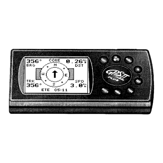
- Page 60 Selecting a User-Defined Navigation Page route, the GPS II of two navigation pages: Fig. 54a tion, and your current speed and track over the ground. You can switch to either Navigation Page at any time. Fig. 54b Once you’ve selected a GOTO destination or activated a TracBack, MOB, or will provide graphic steering guidance to the destination with one •The Compass Page (default) provides a directional pointer to the destination,...
- Page 61 Selecting a User-Defined Navigation Page (cont.) The ‘ETE’ field, located in the middle of the bottom of both pages, is a user-selectable field that allows you to display a variety of navigation values for your trip. To access the user-selectable field: 1.
- Page 62 (based on your current speed and track over the ground), the GPS II The GPS II ’ s Compass Page (Fig. 56 and p. 57) provides graphic steering guid- This page provides better steering guidance than the Highway Page for travel at...
- Page 63 Destination Bearing to Waypoint Distance to Waypoint Waypoint Pointer to Graphic Waypoint Compass Ring Speed Over Track Over Ground Ground Estimated Time Enro u t e ( U s e r-Selectable Field)
- Page 64 “finish line” will move toward the bottom of the highway. When the finish line reaches the CDI scale, you’ve arrived at your destination. The GPS II ’ s Highway Page (Fig. 58 and p. 59) also provides graphic steering...
- Page 65 Destination Bearing to Waypoint Distance to Waypoint Waypoint Graphic Scale Highway Speed Over Track Over Ground Ground Estimated Time Enro u t e ( U s e r-Selectable Field)
- Page 66 The GPS II The map portion of the page displays your present position as a diamond icon, with your track and/or route displayed as small points (electronic breadcrumb trail that “flashes”...
- Page 67 Bearing to Distance to Waypoint Waypoint Route Line Track Log Panning Track Over Speed Over Cursor Present Ground Ground Position...
- Page 68 Zooming and Panning panning, and pointing. The map has 18 map scales (from 0.2 to 00 miles, or 0.3 to 800 km) which are selected by pressing the IN and OUT zoom keys. These ranges are measured vertically, from the bottom of the screen to the top. Fig.
- Page 69 Zooming and Panning (cont.) As you begin to move the map, a crosshair appears (Fig. 63a). This crosshair will serve as a target marker for the map. The distance and bearing to a destination will be replaced by the distance and bearing from your present position to the target crosshair. Fig.
- Page 70 Fig. 64a point is displayed on the map. The GPS II responding symbol (e.g., “fuel” and a gas pump symbol) (Fig. 64a), a symbol only (e.g., a fish symbol) (Fig. 64b), or a 16-character comment and corresponding symbol (e.g., “great view” and the camp site symbol) (Fig. 64c). The waypoint name has a six character limit while the ‘comment’...
- Page 71 To select a waypoint display option: 1. Highlight the symbol field (to the right of the name field), and press ENTER. 2. Move the cursor to the ‘display’ field (Fig. 65a), and press ENTER. 3. Select a display option, and press ENTER to select one of the following display options: ‘name with symbol,’...
- Page 72 Using the Cursor to Mark and GOTO Waypoints with the range and bearing to the target displayed at the top corners of the screen. You can also use the target crosshair to mark a new waypoint position or as a GOTO destination right from the map field.
- Page 73 Accessing the Map Pages You can access four additional pages—the map setup page, the track setup page, the find city page, and the city setup page—by pressing ENTER while on the Map Page (Fig. 67a). To select one of these options: 1.
- Page 74 The rest of the map setup page lets you specify what items are displayed or plotted on the Map Page by selecting ‘YES’ or ‘NO’ in the appropriate field. Fig. 68 O n - s c reen range rings help you estimate distances relative to your present position.
- Page 75 Track Setup Page The track setup page lets you manage the GPS II page, you can select whether to record a track log and define how it is recorded. To turn the track log on or off: 1. Highlight the ‘record’ field, and press ENTER.
- Page 76 Track Log Display on the Map Page. The default setting of 250 points provides good resolution with minimal screen clutter. The maximum setting is 1024 points. Once you’ve reached the maximum number of track points, the older points will be lost as new points are added.
- Page 77 The latitiude and longitude of the city location will be displayed along with a bearing and distance from either the current GPS position or a reference waypoint. To view the city location on the map: 1.
- Page 78 Find City Page (cont.) Fig. 72a be created and added to the user waypoint list. City Setup Page divided into three categories: small, medium, and large. Note: Small cities may not be visible on the map at high zoom settings. Fig.
- Page 79 Menu Page The GPS II ’ s Menu Page provides access to additional pages (submenus) that are used to select and customize operation and navigation setup (Fig. 73a). These seven pages are divided into categories by function. We’ve already gone over the waypoint and route management pages in their respective sections.
- Page 80 Distance and Sun Calculations between any two waypoints or between your present position and a waypoint. It will also calculate the sunrise and sunset (in local time) for a particular date at either your present position or any stored waypoint. Fig.
-
Page 81: Simulator Mode
System Submenu The system submenu page (Fig. 75a) is used to select the operating mode, time offset, and screen preferences. The GPS II • Normal Mode operates the unit at maximum performance, and provides bat- tery life of up to 24 hours on alkaline batteries. - Page 82 Date and Time Setup information is derived from the GPS satellites and cannot be changed by the user. Because the time shown is UTC (Greenwich mean time) time, you will need to enter a time offset to display the correct local time for your area. To determine the time offset for your area, note your position and refer to the chart in Appendix F .
- Page 83 Screen Contrast The GPS II has adjustable screen contrast controlled by an on-screen bar scale. To set the screen contrast: 1. Highlight the ‘contrast’ field, and press ENTER. 2. Adjust the bar scale to the desired contrast, and press ENTER.
- Page 84 Fig 78b The navigation setup submenu page (Fig. 78a) is used to select units of measure- The default position format for the GPS II To select a position format: 1. Highlight the ‘posn’ field, and press ENTER (Fig. 78b). Select the desired setting, and press ENTER.
- Page 85 Map Datums The ‘datum’ field is located just below the ‘position’ field and comes with a WGS 84 default setting. Although 106 total map datums are available for use (see Appendix E for map datums), you should only change the datum if you are using maps or charts that specify a different datum than WGS 84.
- Page 86 To enter a CDI scale setting: 1. Highlight the ‘cdiscale’ field (Fig. 80a), and press ENTER. 2. Select the desired setting, and press ENTER. The GPS II lets you select statute (default), nautical, or metric units of measure To change the unit of measure: 1.
- Page 87 Magnetic Heading Reference The GPS II ’ s heading information can be displayed referencing magnetic north (automatic or user-defined), true north, or calculated grid headings. The default setting is automatic magnetic north, which is suitable for most applications. To select a heading reference: 1.
- Page 88 Alarms Submenu The arrival alarm will alert you when you are approaching a waypoint and have reached the user-defined distance. The CDI alarm will alert you when your track varies from the shortest distance to a waypoint by the defined range. Fig.
- Page 89 The GRMN/GRMN setting is a proprietary format that lets you exchange informa- tion such as waypoints, routes, and track logs between two GARMIN GPS units or a GARMIN GPS and a PC. There are eight data transfer options: send alm, send wpt, send trk, send rte, request alm, request wpt, request trk, request rte.
- Page 90 You may also enter your own frequency and bit rate if desired. Fig. 84b The last two format settings allow the differential-ready GPS II Once a RTCM setting has been selected, the GPS II To enter a DGPS beacon frequency: 1.
- Page 91 When the GPS II is receiving DGPS corrections from the GBR 21, the ‘beacon receiver’ sec- tion of the I/O setup page will display the beacon frequency and signal strength, as well as the distance from the transmitter to the beacon receiver. At the bottom of the beacon receiver field, a status message will keep you informed of DGPS activity: •...
- Page 92 ENTER. You may also enter a new position if you desire (from the Position Page). Fig. 86b The GPS II ’ s simulator mode lets you practice all aspects of its operation without To activate the simulator: 1.
- Page 93 ™ two Velcro strips provided with the unit. To mount the GPS II using the Velcro strips: 1. Select a location for the unit that provides a clear and unob- structed view of the sky.
-
Page 94: Specifications
The GPS II is constructed of high-quality materials and should not require user maintenance. If your unit ever needs repair, please take it to an authorized GARMIN service center. The GPSII Never attempt any repairs yourself. To protect your GPS II not in use, and never allow gasoline or other solvents to come into contact with the case. - Page 95 Battery Life†: Up to 24 hours †Note: Alkaline batteries lose a significant amount of their capacity as temperature decreases. Use lithium batteries when operat- ing the GPS II + in below-freezing conditions. Extensive use of screen backlighting will significantly reduce battery life.
- Page 96 Input/Output devices. • Cigarette Lighter Adapter— Allows connection to a 12-volt DC cigarette lighter plug. • Data Cross-Load Cable— Allows data transfer between other GARMIN GPS units. • PC Kit Data Cable— PC interface cable with 9-pin ‘D’ serial data connector.
- Page 97 DGPScorrections are accepted on RTCM-104 v. 2.0 format. The GARMINGBR 21 is the recommended beacon receiver for use with the GPS II + . Other receivers with the correct RTCM format may be used but may not correctly display status or allow tuning...
- Page 98 Remote Antenna Installation The GPS II ’ s antenna may be removed to allow attachment of an optional remote-mount GPS antenna for certain applications. To remove the attached antenna: 1. Rotate the antenna toward the rear of the unit as shown.
- Page 99 Check other navigational sources to verify the position indicated. Already Exists—The name you are entering already exists in the GPS II + ’ s memory. Approaching—You are one minute away from reaching a des- tination waypoint. Arrival at—You have reached your destination waypoint.
- Page 100 Real Time Clock Failed—The unit’s internal clock has failed. Take your unit to an authorized GARMIN dealer for repairs. Read Only Mem has Failed—The permanent memory has failed and the unit is not operable. Take your unit to an autho- rized GARMIN dealer for repairs.
-
Page 101: Map Datums
Map Datums The following are the map datums available for the GPS II + . Menu Page abbreviations are listed first, followed by the corresponding map datum name and area. The default map datum for the GPS II + is WGS 84. - Page 102 Map Datums (cont.) Corrego Alegr Corrego Algre-Brazil Djakarta Djakarta (Batavia)- Sumatra Island (Indonesia) Dos 1968 Dos 1968- Gizo Island (New Georgia Islands) Easter Isld 67 Easter Island 1967 European 1950 European 1950- Austria, Belgium, Denmark, Finland, France, Germany, Gibraltar, Greece, Italy, Luxembourg, Netherlands, Norway, Portugal, Spain, Sweden, Switzerland European 1979...
- Page 103 Map Datums (cont.) Mahe 1971 Mahe 1971- Mahe Island Marco Astro Marco Astro- Salvage Island Massawa Massawa- Eritrea (Ethiopia) Merchich Merchich- Morocco Midway Ast ‘61 Midway Astro ‘61- Midway Minna Minna- Nigeria NAD27 Alaska North American 1927- Alaska NAD27 Bahamas North American 1927- Bahamas (excluding San Salvador Island) NAD27 Canada...
- Page 104 Map Datums (cont.) Old Egyptian Old Egyptian- Egypt Old Hawaii+an Old Hawaii+an- Mean Value Oman Oman- Oman Ord Srvy GB Old Survey Grt Britn- England, Isle of Man, Scotland, Shetland Isl., Wales Pico De Las Nv Canary Islands Ptcairn Ast ‘67 Pitcairn Astro ‘67- Pitcairn Isl.
- Page 105 Time Offset Chart The table below gives approximate UTC time offsets for various longitudinal zones. If you are in daylight savings time, add one hour to the offset. Longitudinal Zone W180.0º to W172.5º W172.5º to W157.5º W157.5º to W142.5º W142.5º to W127.5º W127.5º...
- Page 106 GOTO Function ... .16,40 GPS Overview ....1 Heading Selection ... . .81...
- Page 107 Initialization ....7-9 Installation, wiring ... . .90 Installation, antenna ... .92 Interface Formats .
- Page 108 Routes ....46-53 Active Route Page ...50 Activating and Inverting ..49 Copying and Clearing .
- Page 110 The unit should be securely packaged with the tracking number clearly marked on the outside of the package and sent freight prepaid and insured to a GARMIN warranty service station. A copy of the orig- inal sales receipt is required as the proof of purchase for warranty repairs. GARMIN retains the exclusive right to...
- Page 111 Notes:...
- Page 112 ® © 1998 GARMIN Corporation 1200 E. 151st Street, Olathe, KS 66062 US Web Site Address: www.garmin.com GARMIN (Europe) Ltd., Unit 5, The Quadrangle, Abbey Park Industrial Estate, Romsey SO51 9AQ UK Part Number 190-00130-10 Rev. A...
Need help?
Do you have a question about the GPS II Plus and is the answer not in the manual?
Questions and answers