
Related Manuals for Dover Wayne Select S1


Summary of Contents for Dover Wayne Select S1
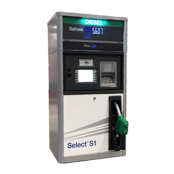
- Page 1 Installation / Operation Wayne Select™ S1 Compact Electronic Dispensers 3/G7100 Series W2940305 Rev 07...
- Page 2 For the purpose of this manual: the product designated on the front cover will be defined herein after as the “Product;” and Dover Fueling Solutions (“DFS”), will reference different entities based on the point of origin for which the Product is manufactured. For Products from North America, DFS references Wayne Fueling Systems LLC located in Austin, Texas.
- Page 3 INDICATORS AND NOTATIONS Danger indicates a hazard or unsafe practice which, if not avoided, will result in severe injury or DANGER possibly death. WARNING Warning indicates a hazard or unsafe practice which, if not avoided, may result in severe injury or possibly death.
- Page 4 This page intentionally left blank...
-
Page 5: Table Of Contents
Complete Installation ....................36 Complete Warranty Registration ................36 Operation......................... 37 Safety Items You Should Know ................37 5.1.1 Portable Tanks and Containers ................38 W2940305 Rev 07 8/2019 Dover Fueling Solutions... - Page 6 Quick Exit from Functions or Statistics ..............78 Pulse Output Interface Option Settings ..............79 E.10 List of Statistics ......................80 E.11 Meter Number Assignments ..................81 E.12 Configuration Functions ................... 82 Dover Fueling Solutions W2940305 Rev 07 8/2019...
- Page 7 Appendix M: Internal Wiring & Connections ..............135 Internal Wiring ......................135 Internal Wiring – iXFleet & Connectors ..............136 Appendix N: Warranty Registration ................... 137 Warranty Registration Instructions ................ 137 W2940305 Rev 07 8/2019 Dover Fueling Solutions...
- Page 8 This page intentionally left blank Dover Fueling Solutions W2940305 Rev 07 8/2019...
-
Page 9: Introduction
Enhanced Capacity: Remote dispenser models with one iMeter fuel meter measuring chamber per hose. Super-High Capacity (SHC): Remote dispenser models with two iMeter fuel meter measuring chambers per hose for increased flow performance. W2940305 Rev 07 8/2019 Dover Fueling Solutions... -
Page 10: Model Description
D3/G7107D/R - DEF Enhanced Capacity Inlet Note: Hose Outlet Adding iX Fleet or T7 option makes unit taller but has no impact on basic model Display information. Nozzle Boot Meter, Filter & Valve Dover Fueling Solutions W2940305 Rev 07 8/2019... -
Page 11: Model Designation Format
D1 iX Fleet, RF Tags, 1‐Sided D3 iX Fleet, Mag Cards, 1‐Sided D5 iX Fleet, Keypad, 1‐Sided D7 iX Fleet, HID‐Prox Cards, 1‐Sided D9 iX Fleet, HID‐Indala Cards, 1‐Sided Hose Mast L Heater Second R Pump Direct Drive Relay Options Suffix S All Stainless Steel S1 Stainless Side Panels, Top, Base Halves w/ Painted Doors S2 Stainless Steel Doors Only T1 T7 Base assembly T2 T7 Contactless T3 T7 Scanner T4 T7 Contactless & Scanner V4 Bezel Security (ix Fleet & T7 option only) W2940305 Rev 07 8/2019 Dover Fueling Solutions... -
Page 12: Technical Information
Cabinet: Galvanealed metal. Removable front and rear doors. Optional SS. Finish: Silver powder coat finish with blue powder coated doors. Optional black, green, red, silver, white, or yellow powder-coated doors. Dover Fueling Solutions W2940305 Rev 07 8/2019... - Page 13 National Conference of W & M: C of C #99-122 FCC certified Note: Dispensers that are UL Certified bear the UL Listing mark. Dispensers listed for both the US and Canadian market carry a cULus label. W2940305 Rev 07 8/2019 Dover Fueling Solutions...
- Page 14 This page intentionally left blank Dover Fueling Solutions W2940305 Rev 07 8/2019...
-
Page 15: Site Design & Preparation
Northbrook, IL 60065 National Assoc. Corrosion Engineers (312) 498-1980 (NACE) (continued on next page) Box 218340 Houston, TX 77218 (713) 492-0535 National Fire Protection Association (NFPA) One Batterymarch Park Quincy, MA 02269-9101 (617) 770-3000 W2940305 Rev 07 8/2019 Dover Fueling Solutions... -
Page 16: Safety Precautions
Garages 2000 Edition, Copyright ©2000, National Fire Protection Association, Quincy MA 02269. This reprinted material is not the complete and official position of the National Fire Protection Association on the referenced subject, which is represented only by the standard in its entirety. Dover Fueling Solutions W2940305 Rev 07... -
Page 17: Ethanol And Bio-Diesel Installations
If the dispenser is to be installed on an existing installation, it is still the responsibility of the installer to read and follow this installation manual in its entirety and make sure the existing installation meets the requirements and satisfies local, state, and federal codes. W2940305 Rev 07 8/2019 Dover Fueling Solutions... -
Page 18: Island Construction, Dispenser Anchoring, Piping, And Bollards
Laboratories, Inc. is one example of a Nationally Recognized Testing Laboratory. For more information on NRTL’s, see Title 29, Parts 1907 and 1910 of the Code of Federal Regulations, Safety Testing or Certification of Certain Workplace Equipment and Materials. Dover Fueling Solutions W2940305 Rev 07... -
Page 19: Installation
Gate Valve Pump Select S1 (Block Valve) Expansion Relief Valve (If Solenoid Valve has pressure relief, separate relief valve is not needed.) Conduit Seal-off 1-1/2" Emergency Double-Poppet Shear Valve Cutaway View Shelf Bracket W2940305 Rev 07 8/2019 Dover Fueling Solutions... -
Page 20: Electrical Wiring
AC Hot Control Power (Hot) standard electrical inputs and outputs Pump Hot In Pump Direct Drive Relay (Optional) utilized in the Wayne Select S1 Series Subm Subm Relay Control X and can provide assistance in Pump Hot Out Pump Direct Drive Relay (Optional) interpreting the Wiring Diagrams in Appendix B. -
Page 21: Electrical Termination Descriptions - Pulse Output Interface Option
Neutral connection for AUTH & RESET signals Wiring Diagram in Appendix C. These connections are found on the optional Pulse Output terminal block 10 N/A located in the head of the dispenser. 11 N/A 12 N/A W2940305 Rev 07 8/2019 Dover Fueling Solutions... - Page 22 Management Systems cannot sense voltage and sense current for the reset output (e.g. OPW PetroVend K800, PetroVend System2). Check the installation requirements of the fuel management system to determine if they require, and supply, additional components such as Dover Fueling Solutions W2940305 Rev 07...
-
Page 23: Circuit Breakers & Emergency Electrical Disconnect
Make sure a ground rod is properly installed and wired to the ground bus strip of the main electrical service panel in accordance with the National Electrical Code. Unless prohibited by local regulations, it is recommended that the neutral and ground bus strips be tied together. W2940305 Rev 07 8/2019 Dover Fueling Solutions... -
Page 24: Wire Type
The total cross- section area of the wiring feeding through one of the conduit fittings is not to exceed 0.092 sq. in. or 59.6 sq. mm. 3/4" Conduit Dover Fueling Solutions W2940305 Rev 07 8/2019... -
Page 25: Gasoline & Diesel Hose And Accessories Installation
These devices must be installed and maintained per the manufacturer’s instructions. Refer to your state and local codes for breakaway device requirements that apply to your installation. W2940305 Rev 07 8/2019 Dover Fueling Solutions... -
Page 26: Vapor Recovery Nozzles
Incompatible material can also contaminate the DEF which can potentially damage to the vehicle’s SCR system. The use of improper nozzles can lead to DEF being dispensed into diesel or other fuel tanks. This could cause serious damage to the vehicle’s engine. Dover Fueling Solutions W2940305 Rev 07... -
Page 27: Start-Up
NOTE: Do not use the Select S1 dispenser to remove water from the tank. It will harm the dispenser components. To prevent damage to the components located in the hydraulic cabinet, dispenser doors should be closed during rainy and/or icy weather conditions. W2940305 Rev 07 8/2019 Dover Fueling Solutions... -
Page 28: Configuring The Dispenser Software
NOTE: The nozzle hook on/off lever must be in the “off” position to access the configuration. Figure 4-1 Infrared Remote Control (IRC) DFS PN: WM002290 Dover Fueling Solutions W2940305 Rev 07 8/2019... -
Page 29: Configuration Start-Up (Units Without Price Displays)
Type the current year in the format of 13 Enter current year in YYYY 2.02 YYYY & Press <ENTER> format] 14 Return to function Press <ENTER> again - - - - - - F 02 level W2940305 Rev 07 8/2019 Dover Fueling Solutions... -
Page 30: Configuration Start-Up (Units With Price Displays)
2 Enter default service Type <111> & Press <ENTER> PASS 2 [blank] [blank] engineer password 3 Re-enter default service Software Type <111> & Press <ENTER> Software Date F - - engineer password Version Dover Fueling Solutions W2940305 Rev 07 8/2019... - Page 31 - - - - - - Mode, 1.00 2=Standalone/ Pulse Output 2=Standalone Mode & Press <ENTER> mode] 19 Return to function level Press <ENTER> again - - - - - - [blank] F 01 W2940305 Rev 07 8/2019 Dover Fueling Solutions...
- Page 32 37 Return for Function level Press <ENTER> - - - - - - [blank] F 03 45 Return to function level Press <ENTER> again - - - - - - [blank] F 04 Dover Fueling Solutions W2940305 Rev 07 8/2019...
- Page 33 1 = Do not exit & do not save changes 2 = Exit & do not save changes 3 = Exit & save changes [Current 50 Exit configuration Press <ENTER> again CHAnGE StorEd Price] W2940305 Rev 07 8/2019 Dover Fueling Solutions...
-
Page 34: Set The Pulse Output Resolution (Pulse Output Interface Option Only)
*NOTE: Enhanced capacity models can be identified by a “0” in the second position after the “7” in the model number (e.g. 3/G7107D). Super-high capacity modes have a “2” in this position (e.g. 3/G7127D). Dover Fueling Solutions W2940305 Rev 07... - Page 35 5 = 500 pulses per gallon 6 = 1000 pulses per gallon 9 Return to function level Press <ENTER> again - - - - - - F 19 - Additional Steps Are Continued on Next Page - W2940305 Rev 07 8/2019 Dover Fueling Solutions...
-
Page 36: Operating Units W/ Pulse Output I/F Option Before Control System Is Operational
Appendix C. If wiring the AC authorization line hot is not possible, reference the instructions in Appendix F, Local Authorize / Standalone Operation. All wiring, even if temporary, must be all regulatory codes. Dover Fueling Solutions W2940305 Rev 07... -
Page 37: Bleeding Product Lines
Step 5 Turn the dispenser off by lowering the on/off nozzle hook to the down “off” position. Return the nozzle to the holder. Step 6 Repeat Steps 1 – 5 for each dispenser. W2940305 Rev 07 8/2019 Dover Fueling Solutions... -
Page 38: Meter Check (Calibration)
NOTE: If dispensing DEF, properly dispose of the DEF from the can (see WARNINGS in front of manual.) Step 4 If the values are out of range, follow the calibration procedure in Section 4.7.3. Dover Fueling Solutions W2940305 Rev 07 8/2019... -
Page 39: Calibration Procedure
Step 7 Empty the container back into the tank and let it drain for 10 seconds. If dispensing DEF, properly dispose of the DEF from the can (see WARNINGS in front of manual.) W2940305 Rev 07 8/2019 Dover Fueling Solutions... -
Page 40: Voltage Test
The installer should make sure the following items are left with the fuel site owner: All documentation and manuals Infrared Remote Control Local Authorization Jumper if connected to a fuel control system Complete Warranty Registration Follow the instructions in Appendix L and complete the Warranty Registration. Dover Fueling Solutions W2940305 Rev 07 8/2019... -
Page 41: Operation
See Warning information about this subject on the following pages. Wear safety goggles and protective clothes when dispensing any liquid that may be potentially harmful or hazardous. Change saturated clothing and wash skin promptly with soap and water. W2940305 Rev 07 8/2019 Dover Fueling Solutions... -
Page 42: Portable Tanks And Containers
NOTE: If a control system is not being used, the nozzle may be locked into the nozzle holder to prevent unauthorized usage. Dover Fueling Solutions W2940305 Rev 07... -
Page 43: Displays
Reached transaction fill limit in dispenser’s Cut OFF configuration Error interrupted the transaction (Auth line turned back on before pump handle turned off) iMeter is not calibrated or iGEM is not CErr communicating with WIP on iMeter W2940305 Rev 07 8/2019 Dover Fueling Solutions... -
Page 44: Electromechanical Totalizer
If it is not possible to restart the dispenser using this procedure, or if an error message continues to be displayed, consult appropriate service personnel. Be certain to give the service personnel the amount at which the dispenser stopped and the exact error message. Dover Fueling Solutions W2940305 Rev 07... -
Page 45: Dispenser Statistics & Diagnostics
NOTE: The following table shows the setting for units without price displays. Units with price displays will look slightly different as they typically utilize all three displays. W2940305 Rev 07 8/2019 Dover Fueling Solutions... -
Page 46: Password Protection
Re-type your new password again & 8 Re-enter new service press <ENTER> PASS 33.00 engineer password (dashes will display as you type the digits) - Additional Steps Are Continued on Next Page - Dover Fueling Solutions W2940305 Rev 07 8/2019... - Page 47 19 Go to exit sub-function Press <ENTER> again 0.00 20 Clear display Press”#” [blank] 0.00 0.00 21 Exit & save Type <3> and then press <ENTER> [alternating 22 Exit configuration Press <ENTER> again CHAnGE 0.00 StorEd] W2940305 Rev 07 8/2019 Dover Fueling Solutions...
-
Page 48: Viewing The Electronic Totalizers
S 11 Exit Statistics [alternating 11 Return to statistics current trans. Press <CLEAR> S - - entry point counts for Side A & Side B] [last 12 Exit statistics Press <ENTER> 3 times transaction] Dover Fueling Solutions W2940305 Rev 07 8/2019... - Page 49 16 Go to exit sub-function Press <ENTER> again 0.00 17 Clear display Press”#” [blank] 0.00 0.00 18 Exit and save changes Type <3> & then press <ENTER> [alternating 19 Exit configuration Press <ENTER> again CHAnGE 0.00 StorEd] W2940305 Rev 07 8/2019 Dover Fueling Solutions...
- Page 50 This page intentionally left blank Dover Fueling Solutions W2940305 Rev 07 8/2019...
-
Page 51: Maintenance
Some applications, such as aircraft refueling, require special filtration equipment in order to ensure product purity. Replacement filters must be UL- recognized. W2940305 Rev 07 8/2019 Dover Fueling Solutions... -
Page 52: Strainer/Filter - Def Dispensers
DFS Support Center at: 1-800-289-2963 OR support.austin@doverfs.com CAUTION Any modification, repair, or service to the dispenser, not in accordance with the original design, may invalidate compliance with the equipment certifications. Consult manufacturer as necessary. Dover Fueling Solutions W2940305 Rev 07 8/2019... -
Page 53: Appendix A: Dimensions & Base Layouts
Appendix A: Dimensions & Base Layouts W2940305 Rev 07 8/2019 Dover Fueling Solutions... - Page 54 Front the iMeter. Discharge Location 3/4" Conduits 11 3/8 in. (2 or 3 Provided) Front of Dispenser [289.0 mm] Top View of Base 22 3/4 in. [578.0 mm] Dover Fueling Solutions W2940305 Rev 07 8/2019...
- Page 55 [100.0 mm] 1-1/2" NPT Inlet 9 1/8 in. [232.5 mm] 3/4" Conduits 11 3/8 in. Front of Dispenser (2 or 3 Provided) [289.0 mm] Top View of Base 22 3/4 in. [578.0 mm] W2940305 Rev 07 8/2019 Dover Fueling Solutions...
- Page 56 [232.5 mm] same place as shown for the iMeter. 3/4" Conduits 11 3/8 in. (2 or 3 Provided) Front of Dispenser [289.0 mm] Top View of Base 22 3/4 in. [578.0 mm] Dover Fueling Solutions W2940305 Rev 07 8/2019...
- Page 57 [232.5 mm] same place as shown for the iMeter. 3/4" Conduits 11 3/8 in. (2 or 3 Provided) Front of Dispenser [289.0 mm] Top View of Base 22 3/4 in. [578.0 mm] W2940305 Rev 07 8/2019 Dover Fueling Solutions...
- Page 58 [100.0 mm] 1-1/2" NPT Inlet 9 1/8 in. [232.5 mm] 3/4" Conduits 11 3/8 in. (2 or 3 Provided) Front of Dispenser [289.0 mm] Top View of Base 22 3/4 in. [578.0 mm] Dover Fueling Solutions W2940305 Rev 07 8/2019...
- Page 59 [100.0 mm] 1-1/2" NPT Inlet 9 1/8 in. [232.5 mm] 3/4" Conduits 11 3/8 in. Front of Dispenser (2 or 3 Provided) [289.0 mm] Top View of Base 22 3/4 in. [578.0 mm] W2940305 Rev 07 8/2019 Dover Fueling Solutions...
- Page 60 17 5/8 in. [448.1 mm] 7 in. Holes for [177.8 mm] mounting shelf bracket 4 in. [101.7 mm] 9 7/8 in. [251.8 mm] 19 7/8 in. [503.6 mm] 21 5/8 in. [548.8 mm] Dover Fueling Solutions W2940305 Rev 07 8/2019...
-
Page 61: Appendix B: Electrical Ratings & Wiring Diagram
T7 option includes heater in amperage * Pump Motor being driven will determine this value and is not to exceed 14 Amps @ 120 VAC or 7 Amps at 240 VAC. W2940305 Rev 07 8/2019 Dover Fueling Solutions... -
Page 62: Wiring Diagram: All Models
Wiring Diagram: All Models Dover Fueling Solutions W2940305 Rev 07 8/2019... -
Page 63: Appendix C: Pulse Output Interface
Reset Output: Some Fuel Management Systems cannot sense voltage and sense current for the reset output (e.g. OPW PetroVend K800, PetroVend System2). Check the installation requirements of the fuel management system to determine if they require, and supply, additional components such as a voltage to current sense convertor. W2940305 Rev 07 8/2019 Dover Fueling Solutions... -
Page 64: Pulse Output Interface Board Layout
(Internal Cabling) Authorization A1 LED Authorization Input Connector (Field Wiring) Pulser A1 LED Pulse Output (Field Wiring) Reset Complete A1 & B1 Reset Complete A1 LED (Internal Cabling) Reset Complete Connector (Field Wiring) Dover Fueling Solutions W2940305 Rev 07 8/2019... -
Page 65: Appendix C: Dispenser Current Loop & T7 Payment Terminal Connections
A high-speed Ethernet connection is required for Wayne iSense remote monitoring, Wayne iX Media platform, and Wayne inOvationTV media. In order for a payment terminal to operate in any mode other than EMV, an RS485 connection is required. W2940305 Rev 07 8/2019 Dover Fueling Solutions... -
Page 66: C.3 Site Layouts
This site configuration can run Payment Terminals (CATs) that are not running in the EMV mode. Forecourt Ethernet Port iX Gateway Controller Switch Dispenser Current Loop Field Wiring Router Modem CAT RS485 Field Wiring Gallons Gallons $ Price Per Gallon $ Price Per Gallon Dover Fueling Solutions W2940305 Rev 07 8/2019... -
Page 67: Site Layout B
Forecourt Ethernet Port iX Gateway Controller Switch Router Dispenser Current Loop CAT Ethernet Field Wiring Field Wiring Modem CAT RS485 Field Wiring Gallons Gallons $ Price Per Gallon $ Price Per Gallon W2940305 Rev 07 8/2019 Dover Fueling Solutions... -
Page 68: Site Layout C
Ethernet Port iX Gateway Controller Switch Dispenser Current Loop Field Wiring Router Wayne Connect Wireless Access Point CAT RS485 Field Wiring Modem Wireless Wireless Gallons Gallons $ Price Per Gallon $ Price Per Gallon Dover Fueling Solutions W2940305 Rev 07 8/2019... -
Page 69: Site Layout D
Wayne inOvationTV media. Forecourt Ethernet Port iX Gateway Controller Switch Router Dispenser Current Loop CAT Ethernet Field Wiring Field Wiring Modem Gallons Gallons $ Price Per Gallon $ Price Per Gallon W2940305 Rev 07 8/2019 Dover Fueling Solutions... -
Page 70: Site Layout E
Wayne inOvationTV media. Forecourt Ethernet Port iX Gateway Controller Switch Dispenser Current Loop Field Wiring Router Wayne Connect Wireless Access Point Modem Wireless Wireless Gallons Gallons $ Price Per Gallon $ Price Per Gallon Dover Fueling Solutions W2940305 Rev 07 8/2019... -
Page 71: Point-To-Point Dispenser To Fusion Forecourt Controller Wiring
Each GRIB connector can handle up to 2 dispensers (for up to a total of 4 fueling positions). For full details of DFS control systems interconnections see the Fusion HyperPIB manual PN 940039. W2940305 Rev 07 8/2019 Dover Fueling Solutions... -
Page 72: Point-To-Point Dispenser To Fusion Udb Replacement Wiring
Each GRIB connector can handle up to 2 dispensers (for up to a total of 4 fueling positions). For full details of DFS control systems interconnections see the Fusion UDB Replacement manual PN 940050. Dover Fueling Solutions W2940305 Rev 07 8/2019... -
Page 73: Point-To-Point Dispenser To Data Distribution Cabinet Wiring
C, 600V, Gas and Oil Resistant, 18 AWG. The use of twisted pair cables can enhance communication for longer distances. For full details of DFS control systems interconnections see the manual provided with the system. W2940305 Rev 07 8/2019 Dover Fueling Solutions... -
Page 74: Wiring Using One Data Distribution Cabinet (Up To 16 Dispensers)
Distribution Cabinet as well as the distance between each dispenser and the Data Distribution Cabinet. See the TB5/TB6 jumper requirements for each loop according to the drawing above. TB5 is associated with Loop A and TB6 is associated with Loop B. Dover Fueling Solutions W2940305 Rev 07 8/2019... -
Page 75: Wiring Using Two Data Distribution Cabinets (Up To 24 Dispensers)
This length of 1800 feet includes the distance between the HyperPIB and the Data Distribution Cabinet, the distance between the first and second Data Distribution Cabinet, and the distance between each dispenser and the Data Distribution Cabinets. W2940305 Rev 07 8/2019 Dover Fueling Solutions... -
Page 76: Payment Terminal Rs485 Wiring
AWG wire). The 2000 feet includes the total length of wiring to handle the Payment Terminals in both dispensers. For full details of Wayne control systems interconnections see the Wayne Fusion Emulation, and Console manual (PN 1000/3000 Forecourt System HyperPIB, PAM 000-940039-). Dover Fueling Solutions W2940305 Rev 07 8/2019... -
Page 77: C.10 Ethernet Connection
When installing the cable, allow the Ethernet cable to extend at least 30” above the vapor barrier. For proper assembly and potting of the cable, see section 3.3.7 of the Electrical wiring section. W2940305 Rev 07 8/2019 Dover Fueling Solutions... - Page 78 Pin 1 Pin 8 T568B 1 2 3 4 5 6 7 8 T568A T568B Pair T568A Color Pair T568B Color green striped orange striped green orange orange striped green striped orange green Dover Fueling Solutions W2940305 Rev 07 8/2019...
-
Page 79: Appendix E: Dispenser Software Configuration, Statistics & Diagnostics
You are now at the function level (F - - on Status display). Reference Section D.3, IRC Commands, on how to navigate the functions. If you wish to enter Statistics mode, press the <Down> key. W2940305 Rev 07 8/2019 Dover Fueling Solutions... -
Page 80: Irc Commands
NOTE: When in Statistics Mode (S - - or S “xx” on Status display), the above commands work the same way. When at S - -, the <UP> or <DOWN> keys take you to F - -. Dover Fueling Solutions W2940305... -
Page 81: Changing Subfunction Values
Display CLEAr 1 Clear total Press <#> xx.xx totALS 2 Confirm clear Press <ENTER> PASS xx.xx 3 Enter reset password Type <42> & Press <ENTER> - - - - - - S xx W2940305 Rev 07 8/2019 Dover Fueling Solutions... -
Page 82: Exiting Functions
In Statistics, you will go to S - -. point software revision & F - - In Functions, you will go to F - -. date] 2 Exit statistics or [last transaction Press <ENTER> three times functions volume] Dover Fueling Solutions W2940305 Rev 07 8/2019... -
Page 83: Pulse Output Interface Option Settings
F01 set to “1” (i.e. an iX Fleet system), the F41.01 must be enabled and F19.25 (gallons) or F19.15 (liters) must be set to the desired pulse ration. The other pulse output setting are ignored in this serial connection mode. W2940305 Rev 07 8/2019 Dover Fueling Solutions... -
Page 84: E.10 List Of Statistics
Side A WIP (Pulser) S 17 17.M0 models have two meters per hose.) Volume Totalizers Note: See Meter Number Assignments table at the end of this section to determine the meter numbering for your model. Dover Fueling Solutions W2940305 Rev 07 8/2019... -
Page 85: E.11 Meter Number Assignments
) E.11 Meter Number Assignments *Note: Super-High Capacity models have two iMeter fuel meters connected to one discharge to provide increased performance. 3/G7107D/R E3/G7107D/R D3/G7107D/R MODEL D3/G7101D/R 3/G7127D/R Meter 1 Meter 2* W2940305 Rev 07 8/2019 Dover Fueling Solutions... -
Page 86: E.12 Configuration Functions
Max. blend error allowed, 1-5 (units of %) First check set for blending if liters, 2-200 (units of 1/10 liters) First check set for blending if gallons, 5-50 (units of 1/10 gallons) Reserved Reserved Dover Fueling Solutions W2940305 Rev 07 8/2019... - Page 87 = none assigned Primary valve number assignment, 0-8, 0 = .51=5 none assigned Primary valve type .61=2 (3 or 4 for 1=on/off UHC models) 2=proportional 3=Two stage UHC ASCO 4=Two stage UHC Parker W2940305 Rev 07 8/2019 Dover Fueling Solutions...
- Page 88 4 =Money and volume actual, unit price blank Money display digits right of decimal point, 0- Volume display digits right of decimal point, Unit price display digits right of decimal point, Dover Fueling Solutions W2940305 Rev 07 8/2019...
- Page 89 4=xFlo, 5=LC & iMeter combo Dispenser Limits Max. # of pulse errors on an in-use pulser (in 10 (50 for UHC) Configuration a transaction), 1-99 Max. # of pulse errors on an idle/unused pulser, 1-99 W2940305 Rev 07 8/2019 Dover Fueling Solutions...
- Page 90 1=1 pulse per unit 2=10 pulses per unit 3=100 pulses per unit 4=250 pulses per unit 5=500 pulses per unit 6=1000 pulses per unit Calibration Test Container Volume – Gallons (UHC only) 5 – 250 Gallons Dover Fueling Solutions W2940305 Rev 07 8/2019...
- Page 91 4=Display Wayne Vac diagnostics Product pressurization function, 1=Enable, 2=Disabled Arming key authorization 0=Disabled 1=Arming req’d in both cash & credit modes 2=Arming req’d in cash mode only 3=Arming req’d in credit mode only W2940305 Rev 07 8/2019 Dover Fueling Solutions...
- Page 92 2=Volume only 3=Default to money 4=Default to volume Preset entry required before filling 1=Preset required 2=Preset not required Fill mode display 1=Display “------“ when fill key pressed 2=Display “FILL” when fill key pressed Dover Fueling Solutions W2940305 Rev 07 8/2019...
- Page 93 6=Switch 6 (normal when enabled) 7=Switch 7 MPI Authorization, Side A, logical nozzle 2 0=Disabled 6=Switch 6 (normal when enabled) 7=Switch 7 Attendant arming switch 0=Disabled 6=Switch 6 (normal when enabled) 7=Switch 7 W2940305 Rev 07 8/2019 Dover Fueling Solutions...
- Page 94 Weights & Measures password, maximum of 6 characters (numeric only) Diagnostics Switch test N = nozzle, S = Stop Switch, B = bitbus, P = Preset Display Test Vapor Recovery subsystem test, Side A (Wayne Vac) Dover Fueling Solutions W2940305 Rev 07 8/2019...
- Page 95 None assigned Primary valve type .61=2 (3 or 4 for 1=On/off UHC models) 2=Proportional 3=Two stage ASCO 4=Two stage Parker Secondary valve number assignment, 0-8, 0 see model chart at = None assigned W2940305 Rev 07 8/2019 Dover Fueling Solutions...
- Page 96 Call Signal, Side A Logical Nozzle 2 * 0=Not used 11=Enable to reset complete output 13=Enable to call output Call Signal, Side B Logical Nozzle 2 * 0=Not used 11=Enable to reset complete output 13=Enable to call output Dover Fueling Solutions W2940305 Rev 07 8/2019...
- Page 97 0 or 1 1-255=Minutes to allow unarmed entry after successful one-shot entry Product Select LED Product Select LED Variable Blink Rate Variable Blink Rate Enable 0=Variable blink rate not enabled 1=Variable blink rate enabled W2940305 Rev 07 8/2019 Dover Fueling Solutions...
- Page 98 Download software code to dispenser from a Memory file on PC. Requires laptop and service terminal program. Download Configuration Download template to dispenser from a file on PC. Requires laptop and service terminal program. Dover Fueling Solutions W2940305 Rev 07 8/2019...
-
Page 99: Appendix F: Local Authorize / Standalone Operation
When the dispenser is equipped with an iX Fleet system, setting the dispenser into Standalone Operation varies if the dispenser also has the optional pulse output feature. Figure F-1 JP1 Standalone Jumper W2940305 Rev 07 8/2019 Dover Fueling Solutions... -
Page 100: Place Dispenser Into Standalone Operation From Pulse Output
In the configuration, change subfunction 27.00 to “0” instead of “8” to set the dispenser back into pulse output interface mode. If the unit has iXFleet, change subfunction 01.00 back to “1” instead of “2”. Dover Fueling Solutions W2940305 Rev 07... -
Page 101: Place Dispenser Into Standalone Operation From Serial Mode
If dispenser is equipped with a Pulse Output Board, verify F27.00 is set to “8”. If not, change it to “8” and leave in this setting even after converting back to the serial mode. W2940305 Rev 07 8/2019 Dover Fueling Solutions... - Page 102 This page intentionally left blank Dover Fueling Solutions W2940305 Rev 07 8/2019...
-
Page 103: Appendix G: Weights & Measures Mode
You do not need a security code to access or obtain information through the Weights & Measures mode. The cabinet does not need to be opened to access this mode. Infrared Remote Control DFS PN: WM002290 Clear Enter Next W2940305 Rev 07 8/2019 Dover Fueling Solutions... - Page 104 "Enter" "Next" OR 20 Sec Timeout Totalizer Meter Readings Press "Clear" OR "Next" OR "Enter" OR 10 Sec Timeout Metrological Settings Menu Program Change Log Details Press Press "Clear" "Enter" "Next" Last Transaction Dover Fueling Solutions W2940305 Rev 07 8/2019...
-
Page 105: Unit Of Measure Menu
Press "Next" Toggles 20 Sec Timeout UC4 thru UC9 - UOM Press "Next" Toggles 20 Sec Timeout UC10 - UOM Press "Next" Press "Clear" Anytime Toggles 20 Sec Timeout Pulse Output Config Menu Toggles W2940305 Rev 07 8/2019 Dover Fueling Solutions... -
Page 106: Pulse Output Menu
Toggles 20 Sec Timeout PO4 - PO9 - UOM/Pulse Rate Press "Next" Toggles 20 Sec Timeout PO10 - UOM/Pulse Rate Press "Next" Press "Clear" Anytime Toggles 20 Sec Timeout ATC Configuration Menu Toggles Dover Fueling Solutions W2940305 Rev 07 8/2019... -
Page 107: Automatic Temperature Compensation (Atc) Menu
Meter 2 Probe Assigned Meter 2 Fuel Type Press "Next" Toggles 20 Sec Timeout Meter 3-8 Probe Assigned Meter 3-8 Fuel Type Press "Next" Press "Enter" to Toggles exit details and move to next "tc" record W2940305 Rev 07 8/2019 Dover Fueling Solutions... -
Page 108: Product Pressurization Menu
Toggles 20 Sec Timeout PP4 - PP9 - PPL Status Press "Next" Toggles 20 Sec Timeout PP10 - PPL Status Press "Next" Press "Clear" Anytime Toggles 20 Sec Timeout Program Change Menu Toggles Dover Fueling Solutions W2940305 Rev 07 8/2019... -
Page 109: Program Change Menu
PC3 - Event Press "Next" Toggles 20 Sec Timeout PC4 - PC9 - Event Press "Next" Toggles 20 Sec Timeout PC10 - Event Press "Next" Press "Clear" Anytime Toggles 20 Sec Timeout Totalizer Meter Readings W2940305 Rev 07 8/2019 Dover Fueling Solutions... -
Page 110: Meter Totals
(tx). You can press “Clear” at any time to move to the next upper menu item. Volume Totals Press "Next" "Enter" Totalizer "Clear" Number Side 10 Sec Timeout Metrological Settings Dover Fueling Solutions W2940305 Rev 07 8/2019... -
Page 111: Metrological Settings Menu
F22-Sales Amount Config F22 - First Setting F22 - Remaining Settings Press Press "Enter" "Next" Press Press "Next" "Next" Press "Enter" OR "Clear" Last Transaction See next page for these configuration parameter definitions. W2940305 Rev 07 8/2019 Dover Fueling Solutions... -
Page 112: G.10 Metrological Configuration Parameter Definitions
Count by ones or fives in least significant digit of money display 1=Ones 2=Fives Volume digits to the right of the decimal point used in the amount Money preset configuration Default price mode 1=Credit 2=Cash Dover Fueling Solutions W2940305 Rev 07 8/2019... -
Page 113: G.11 Automatic Temperature Compensation (Atc) Testing
W&M probe. To compare the Net (compensated) and gross (uncompensated) volumes, you may turn on/off the temp comp switch to changes the volume display between net and gross volume. W2940305 Rev 07 8/2019 Dover Fueling Solutions... - Page 114 This page intentionally left blank Dover Fueling Solutions W2940305 Rev 07 8/2019...
-
Page 115: Appendix H: Ix Fleet Fuel Control System
Controller, can be connected to the controller via an Ethernet switch, or can be connected via a LAN. Dispensers can also be interconnected with each other before the Ethernet connection is routed back to the iX Fleet Fuel Controller. W2940305 Rev 07 8/2019 Dover Fueling Solutions... - Page 116 Board Wiring Switch Switch Wiring Switch "From Server" "From Server" Port Port S1 Dispenser Ethernet Ethernet Board Ethernet Field Board Switch Wiring Switch "From Server" "From Server" Port Port Inside Outside Inside Outside Dover Fueling Solutions W2940305 Rev 07 8/2019...
- Page 117 Conduit (field barrier. Make sure a washer is supplied to used on both sides of the vapor within 5/8” below barrier. Tighten until both washers vapor barrier) are pulled snug against the vapor barrier. W2940305 Rev 07 8/2019 Dover Fueling Solutions...
- Page 118 Add 1-1/2 oz. of water. Stir one to two minutes until reaching consistency similar to pancake batter. Pour mix into fitting and fill to within 1/8” of top of fitting. Cable should exit near the center of the fitting. Dover Fueling Solutions W2940305 Rev 07...
-
Page 119: Ix Fleet Board Setup
Configuration Side A R2 iX Board Side B R2 iX Board Single-Sided Terminated Dual-Sided Unterminated Terminated Terminated – Switches placed toward center of iX R2 board. Unterminated – Switches placed towards edge of iX R2 board. W2940305 Rev 07 8/2019 Dover Fueling Solutions... - Page 120 This page intentionally left blank Dover Fueling Solutions W2940305 Rev 07 8/2019...
-
Page 121: Appendix J: Bezel Security
One Shot Response Entry Time (Remote One-Shot Mode Only) 0 or 2 0=Wait Forever, 1-255=Minutes to Wait for Entry after Challenge Code) 56.07 Re-Arming Time 0 or 1 1-255=Minutes until System Re-Arms after Successful Entry and Door Closed W2940305 Rev 07 8/2019 Dover Fueling Solutions... -
Page 122: Enabling Security Mode
If the display still reads Secure Off after 1 minute, there may be an issue with the security switches. Troubleshoot as needed. 3. Run test sales to verify proper dispenser operation. Dover Fueling Solutions W2940305 Rev 07 8/2019... -
Page 123: Clearing A Breach
5. Press the “Enter” key 3 times to return to the idle state. 6. In 1 minute the dispenser will be armed, will display Secure On , and the dispenser should return to the idle state. W2940305 Rev 07 8/2019 Dover Fueling Solutions... -
Page 124: Maintenance/Service
When the service work is complete, close the bezel. In one minute the security feature will turn on. This can be verified by pressing the Enter key on the remote hand-held (after one minute has elapsed). The display will show Secure On . Dover Fueling Solutions W2940305 Rev 07... -
Page 125: Testing The Switches
3. Press the “Clear” button three times to exit the diagnostic mode. 4. Press the “Enter” button three times to exit the configuration mode and return to the idle state. Be sure to re-enable the security feature once you finish testing the switches. W2940305 Rev 07 8/2019 Dover Fueling Solutions... - Page 126 This page intentionally left blank Dover Fueling Solutions W2940305 Rev 07 8/2019...
-
Page 127: Appendix K: T7 Receipt Printer
General Use the Recommended Paper Using paper that is not recommended for the printer can be a source of printer jams. Use only paper that meets Dover Fueling Solutions specifications. Basic Characteristics Basic Weight 58.0 +5.0 (G/Sq. Meter) Caliper .0023 - .0028 in. -
Page 128: Description Of Indicator Lights & Control Button
Normal Operation Red 1 Flash Paper Jam Red 2 Flashes Cutter Jam Status Light Red 3 Flashes Out of Paper Red 4 Flashes Print Head (Green Lever) Listed Red 5 Flashes Paper Feed Error Dover Fueling Solutions W2940305 Rev 07 8/2019... -
Page 129: Replace Paper
1. Unlock the T7 door by turning the lock and then loosening the door screw. Door Screw Door Lock 2. Swing Open the door to expose the rear of the T7 terminal. This pictures shows a T7 with a full paper roll installed. W2940305 Rev 07 8/2019 Dover Fueling Solutions... - Page 130 3. Remove old paper core. 4. Insert new roll of paper. 5. Push green lever in and lift print head to release old paper. 6. Remove the paper. Dover Fueling Solutions W2940305 Rev 07 8/2019...
- Page 131 8. Firmly push down on the print head with both hands as shown until the print head clicks (latches in place). The paper will automatically advance and cut the paper. 9. Remove the paper. 10. Close the door, tighten the door screw, lock the door and remove the key. W2940305 Rev 07 8/2019 Dover Fueling Solutions...
-
Page 132: Paper Jams
Push in the tabs of the paper guide as shown. Paper Jam – 1 Flash Error Lift paper guide and remove paper. Press the Feed button to advance the paper and print a test receipt. Dover Fueling Solutions W2940305 Rev 07 8/2019... - Page 133 Paper Feed Error – 5 Flash Error Push green lever forward. Lift print head and lift paper away from cutter. Tear paper. Push print head down firmly until it latches. Printer will automatically advance the paper and cut. W2940305 Rev 07 8/2019 Dover Fueling Solutions...
- Page 134 This page intentionally left blank Dover Fueling Solutions W2940305 Rev 07 8/2019...
-
Page 135: Appendix L: Error Codes
Computer errors are read by entering the Maintenance Mode and accessing the correct statistical function and its sub-functions. Perform the following steps using the remote control. Bold type denote remote control function; italicized type represents dispenser response. W2940305 Rev 07 8/2019 Dover Fueling Solutions... - Page 136 No communications with POS timeout Communication lost with POS for the amount of time specified in function 23.02 POS buffer overflow (DART) Communication error with POS Sale aborted because Stop Button pushed Stop button signal was detected Dover Fueling Solutions W2940305 Rev 07 8/2019...
- Page 137 Consecutive unfinished fillings Consecutive sales did not reach the preset limit. Number of sales is specified in function 17.06 DEF Low Temperature Event DEF temperature change signal received; 1=Low Temp, 2=Low Temp Cleared W2940305 Rev 07 8/2019 Dover Fueling Solutions...
- Page 138 Hardware/Software mismatch – Device #s: Hardware configuration problem detected. 0=No proportional hardware, 1=No vapor Hardware signal is missing recovery hardware, 2=Meter does not match F16.04, 3=Ovation II not enough upd’s installed, 4=Ovation II too many upd’s installed Dover Fueling Solutions W2940305 Rev 07 8/2019...
-
Page 139: Appendix M: Internal Wiring & Connections
WM052405-0001 WM052405-0001 Field Field Field J10 J11 J7 J10 J11 887001-001 WU019517-0001 WU003726-0001 WU008647-0001 24V Power Field Wiring TB J10 J11 iGEM Computer Distribution WM001908-0003 24V Power iGEM Computer 887223-001 Distribution WM001908-0003 887223-001 W2940305 Rev 07 8/2019 Dover Fueling Solutions... -
Page 140: Internal Wiring - Ixfleet & Connectors
AC Auth B POB - J5 Pulser B1X+ RELAY-J2 Pulser A1Y- Pulser B1Y- Pulser A1Y+ Pulser B1Y+ Pulser A1X- Pin 1 CPU-J2 PIN 1 Pulser B1X- Pulser A1X+ Pin 5 Violet (Subm X) Dover Fueling Solutions W2940305 Rev 07 8/2019... -
Page 141: Appendix N: Warranty Registration
Phone: Telephone number at the site. Start-up Date: Date equipment was commissioned. Model Number: Model number of equipment from identification tag on equipment. Serial Number: Serial number of equipment from serial number tag on equipment. W2940305 Rev 07 8/2019 Dover Fueling Solutions... - Page 142 1. Any replacement parts and service must be performed by a DFS ASO. If you are not an ASO, you must call 1-800-289-2963 to get service. Any parts and service, performed by an ASO, associated with the start-up should be reported on Service Report Form No. 917652 and attached to this report. Dover Fueling Solutions Attn: Warranty 2.
- Page 143 INSTALLATION & OPERATION MANUAL Wayne Select™ S1 3/G7100 Fleet Dispensers Printed in the United States of America This manual and any software described herein are furnished under the terms of sale or other applicable contract including any license, and may be used or copied only in accordance with those terms. No part of this publication may be electronically or mechanically reproduced, stored in a retrieval system, or transmitted, in any form or by any means, except as permitted by such terms.
- Page 144 This product complies with Part 15 of the FCC rules and regulations. Operation is subject to the following two conditions: (1) This product may not cause harmful interference, and (2) this product must accept any interference received, including interference that may cause undesired operation. This equipment has been tested and found to comply with the limits for a Class A digital device as set forth in Part 15 of the FCC Rules.
Need help?
Do you have a question about the Wayne Select S1 and is the answer not in the manual?
Questions and answers