Table of Contents
Advertisement
Quick Links
Advertisement
Table of Contents

Related Manuals for Dover Wayne Helix WM048523


Summary of Contents for Dover Wayne Helix WM048523
- Page 1 Service Manual Wayne Helix™ Fuel Dispensers WM048523 Rev 08...
- Page 2 Read this manual before starting any installation, service, or maintenance work Fuel dispensers contain both electrical components and a hazardous, flammable and potentially explosive fuel. Failure to follow the below precautions and the Warning and Caution instructions in this manual may result in serious injury. In addition, it is your responsibility to follow all rules, codes, regulations, and laws that apply to your location and type of work being performed.
- Page 3 Maintenance Note The Ex dispensers or other Ex-materials designed and manufactured by Dover Fueling Solution (“DFS”) are fully compliant with the applicable EU directives and harmonised standards (refer to EU DoC for the list of applicable standards).
- Page 4 The instructions for installation and maintenance are contained within the corresponding DFS manuals and must be adhered to. Approved replacement parts are listed in the DFS parts manual. Failure to follow the contents of any of these manuals may invalidate warranty and result in regulatory breaches and potential liability issues.
-
Page 5: Table Of Contents
Table of Contents Table of Contents Introduction ....................... Features ....................... Unlocking the Bezel ..................Payment Terminal ..................Bezel Latches ....................Service Position .................... Non-Payment Bezel ..................Hydraulics ......................... Triple Bump Product Tubes ................Filter and Strainer Remotes ................. Strainer and Filter Suction Pumps ..............Proportional Flow Control Valve .............. - Page 6 Table of Contents iX R2 Board ....................Nozzle Switch Interface Board ..............Nozzle Switch Converter Board ..............Temperature Module (Temp Comp) .............. TTL / CAN Converter Board ................. ISB Board ..................... 4.10 Dispenser Connection Board - Remote Models NA ........4.11 Dispenser Connection Board - Suction Models NA ........
- Page 7 Table of Contents Meter Replacement - Removing Meter from Base ........6.9.1 Check valve replacement ..................6.10 Product Tube Replacement - Using the Tube Removal Tool ....... 6.11 Product Tube Replacement - Not Using the Tube Removal Tool ....6.12 Outlet Casting Replacement ................
- Page 8 Table of Contents Suction Pumps ......................11.1 Compact Pumping Unit ................11.2 By-pass (Relief) Valve Assembly ..............11.3 Float and Valve Seat Assembly ..............11.4 Air Separation ....................11.5 Testing the Suction Pumping System ............11.5.1 Vacuum Test ......................11.5.2 Pressure Test ......................
- Page 9 Table of Contents 15.4 iMeter Replacement ..................15.5 Hose Replacement ..................Helix LPG - IEC ......................16.1 Degassing Unit Replacement ............... 16.2 Differential Valve Replacement ..............16.3 Solenoid Valve Replacement ............... 16.4 Meter Replacement ..................16.5 Degassing Unit Filter Replacement .............. Printer Maintenance ....................
-
Page 11: Introduction
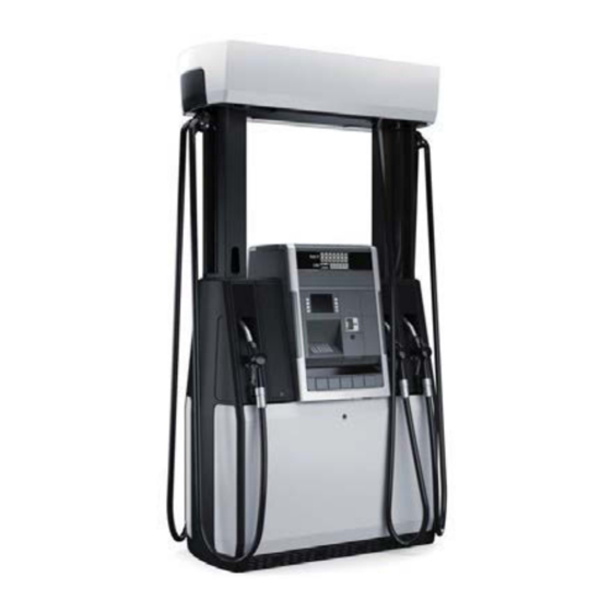
1 Introduction Introduction This manual contains detailed service information for Wayne Helix™ fuel dispensers. This manual applies to Helix 1000, 2000, 4000 (narrow body), 5000 (wide body) and 6000 (C-style) model series. The manual should be used for troubleshooting and repair purposes by Wayne certified technicians only. -
Page 12: Unlocking The Bezel
1 Introduction Unlocking the Bezel Perform the following the steps to open the bezel and payment terminal for service. 1 Unlock bezel U-frame shown in Fig 1.1, then raise the frame to the overhead position. 2 Unlock Payment Terminal Drawer. See lock location in Fig 1.2. 3 Locate the two latches, underneath the payment terminal, then firmly push up on latches and pull out to unsnap. -
Page 13: Payment Terminal
1 Introduction Payment Terminal lock payment terminal Figure 1.2: Payment Terminal Drawer Lock Bezel Latches Locate latch behind PTS panel and push upward. The right side of the bezel is shown here for clarity but there is a latch on both ends of the PTS panel. Push up on the tabs using one hand on each end. - Page 14 1 Introduction Figure 1.3: Latches Behind the Payment Terminal Bezel WM048523 Rev 08 01/2019...
-
Page 15: Service Position
1 Introduction Service Position Figure 1.4: Helix Dispenser Service View WM048523 Rev 08 01/2019... -
Page 16: Non-Payment Bezel
1 Introduction Non-Payment Bezel A typical Non-payment bezel is shown below. See the procedure in the Small Pump section of this manual to gain access for servicing the components in the upper section and in the Lower Electronics Enclosure (LEE). Sales Display Panel Preset/Options... -
Page 17: Hydraulics
2 Hydraulics Hydraulics The hydraulic parts in the Helix dispenser are listed below. These basic parts are discussed in detail in this section. • Product Tubes • Strainer and Filter (Remotes) • Strainer and Filter (Suction Pumps) • Proportional Flow Control Valve •... -
Page 18: Filter And Strainer Remotes
2 Hydraulics Figure 2.1: Triple Bump Tube and Retaining Pin Filter and Strainer Remotes The filter should be changed and the strainer cleaned on a regular basis. A dirty filter and strainer may cause the dispenser to deliver fuel slowly. In some cases, this may appear to be a more serious service related problem, when simply changing the filter and cleaning the strainer is all that is required. -
Page 19: Strainer And Filter Suction Pumps
2 Hydraulics Coupling part of iMeter base Filter Strainer located inside the casting Spill Funnel Figure 2.2: Strainer Casting, Filter, and Spill Funnel Strainer and Filter Suction Pumps Refer to the Suction Pump section of this manual for details. Proportional Flow Control Valve The proportional flow control valve is a pilot-operated solenoid valve located between the meter and the hose outlet. -
Page 20: No Flow - Flow Control Valve Off
2 Hydraulics 2.4.1 No Flow - Flow Control Valve Off Flow control valve “Off” or no flow occurs when the inlet to the valve is charged. But there is no flow required from the particular valve as in the instance where a submersible pump motor is running because another fueling point is being used. - Page 21 2 Hydraulics Coil cable. conduit not used Coil used IEC and NA use the same valve Figure 2.4: IEC Coil WM048523 Rev 08 01/2019...
-
Page 22: Imeter And Xflo
2 Hydraulics iMeter and Xflo The iMeter module, shown in Figure 2.5, contains two meters in one assembly and the Wayne™ Intelligent Pulser (WIP). Each of the two meters in the iMeter module is a positive displacement meter. There are no external moving parts on the iMeter. The WIP pulser has two calibration doors - one for each meter. -
Page 23: Hose Outlet Casting And Retainer Clip
2 Hydraulics Hose Outlet Casting and Retainer Clip The new outlet casting on Helix dispensers, shown in Figure 2.6 below, is smaller and lighter weight than the outlet castings used on previous model series. In addition, as shown in Figure 2.7, this casting incorporates the use of a metal retainer clip that secures the triple bump tube. - Page 24 2 Hydraulics product tube retainer clip Figure 2.7: Tube Retainer Clip Figure 2.8: Tube Removal Tool WM048523 Rev 08 01/2019...
-
Page 25: Vapour Recovery - Iec
2 Hydraulics Vapour Recovery - IEC For service procedures to be used in IEC countries, refer to the following manuals: Title Part Number Vapour Gate WM022301 Burkert, Vapour Recovery Test & Calibration 461307 2.7.1 Extracts from "0544100100L02-V001_EN1608_Dürr VR pump manual" WM048523 Rev 08 01/2019... -
Page 26: Additive - Iec
2 Hydraulics Additive - IEC Filling of additive tank - see the User's Manual, WM048521. In case of Additive System(s) integrated in the dispenser, use only already approved additive(s) to blend product(s) according to dispenser configuration. Additive(s) were defined during order phase when preparation of prearranged dispenser configuration was done, including nozzles flow rates. - Page 27 2 Hydraulics Loosen flex-tube at iMeter2 as shown below. Allow the pipes to pour into a suitable container to catch pumped liquid. To fill the flex pipes with liquid, do the following: Press the CRC button on iGEM2 (see the arrow below) to enable the IR re- mote control.
- Page 28 2 Hydraulics Sign in (”ENTER” , password, ”ENTER”) Press ”UP” until the display shows ”o ---”. Press ”757”,”ENTER”,”ENTER” The display will now toggle between ”o 757” och ”.000” Press ”NEXT” until UP display shows ”.004”. Press”#” followed by the nod-number to be filled (on C34-344 A1 node#1 and node#2 are used).
-
Page 29: Adjusting Of Additive Pump Pressure
2 Hydraulics 2.8.2 Adjusting of additive pump pressure : Pressure adjustment S: Suction inlet G1/4 R: Return outlet G1/4 E: Nozzle outlet G1/8 P: Pressure gauge port G1/8 V: Vacuum gauge port G1/8 H: Filter 1. Loosen plug ”P” and attach the pressure gauge. 2. -
Page 30: Electronics
3 Electronics Electronics Helix dispensers contain the Wayne iGEM™ computer. The iGEM computer, located on side 1 of the dispenser, controls all functions of dispenser operation, except for Wayne™ CAT operations. Wayne CAT operations are controlled by the iX™ R2 board located on side 2 of the dispenser. The iGEM computer contains flash RAM memory and supports IR remote control programming and diagnostics. -
Page 31: Dispenser Connection Board
3 Electronics Dispenser Connection Board The dispenser connection board combines the iGEM AC Relay board and the DC Distribution board and centralizes all the power sources into one location. Current loop and data communi- cations are also distributed from this board. AC power from the dispenser junction box comes into this board at J8. -
Page 32: Nozzle Switch Interface Board
3 Electronics Nozzle Switch Interface Board All nozzle switch cables plug into this interface board. This board is in a blue case mounted on the chassis in the hydraulics cabinet. The board is accessed by lifting the cover off the tabs on the plastic case. -
Page 33: Wip
3 Electronics The Wayne™ Intelligent Pulser (WIP) contains two sets of magnetic sensors - one set for each meter. Inside the meter dome, a rotating magnetic disk generates a changing magnetic field. The sensors detect changes in the magnetic field which the pulser converts to digital pulses. The pulses are adjusted to meter output with a calibration factor that is stored in the pulser memory. -
Page 34: Board Layout And Connector Descriptions
4 Board Layout and Connector Descriptions Board Layout and Connector Descriptions This section shows the locations of the connectors on each of the electronic boards and modules. Pinout information is also provided. While some of the connector pins are not accessible for troubleshooting, the description given for these will help provide an understanding of the board and connector functions. -
Page 35: Igem Computer Board
4 Board Layout and Connector Descriptions iGEM Computer Board For Helix dispensers, the iGEM board must have jumpers on each of the 2- pin connectors SW13A to D, and SW14A to D. Eight jumpers (part number 4043601) are required. If these jumpers are not in place, WIP communications through the Helix ISB board will be disrupted, resulting in error code 59. - Page 36 4 Board Layout and Connector Descriptions Table 4.1: iGEM Board Connectors Connector and Description Connects to Note pin # 24 VDC Power Connection board J41 Typical reading 23.9 - 24.1V Sub pump relays Connection board J13 Typical reading 23.9 - 24.1V 24 VDC Pump motor 2 24 VDC...
- Page 37 4 Board Layout and Connector Descriptions Connector and Description Connects to Note pin # Nozzle switch inputs Nozz Sw Converter Bd J1 Typical reading 5V NOZZ 4 NOZZ 3 NOZZ 2 NOZZ 1 NOZZ 8 NOZZ 7 NOZZ 6 NOZZ 5 WIP IN/OUT ISB J1 Typical reading 14.8 - 15.2V...
- Page 38 4 Board Layout and Connector Descriptions Connector and Description Connects to Note pin # Totalizers from Side 1 Outputs from Tots 1-4 TOT 1 TOT 2 TOT 3 TOT 4 Totalizers from Side 2 Outputs from Tots 5 - 8 TOT 5 TOT 6 TOT 7...
- Page 39 4 Board Layout and Connector Descriptions Connector and Description Connects to Note pin # IEC RS485 Data Link Pump Control Display data cable bit bus Side 1 Display J1 Side A (1) DATA IN A DATA OUT A ADDRESS BIT A CLOCK A BUZZER A STOP A...
- Page 40 4 Board Layout and Connector Descriptions Connector and Description Connects to Note pin # Buzzer power Side 1 Buzzer 1 CAT buzzer Buzz CAT Not used with Helix Wayne Vac Datalink/Current Loop IEC uses J14 for pump control DATA + DATA - Laptop connection Push Buttons...
-
Page 41: 4.2 Igem Board Na
4 Board Layout and Connector Descriptions 4.2 iGEM Board NA WM048523 Rev 08 01/2019... -
Page 42: 4.3 Igem Board Iec
4 Board Layout and Connector Descriptions 4.3 iGEM Board IEC WM048523 Rev 08 01/2019... -
Page 43: 4.4 Ix R2 Board
4 Board Layout and Connector Descriptions 4.4 iX R2 Board WM048523 Rev 08 01/2019... - Page 44 4 Board Layout and Connector Descriptions Connector Description Note TTL Card Reader future use CAN BUS CAN BUS Annunciator RS-422 IEC use RS-232 PORT IEC use RS-485 future use TRSM keypad Audio Out Power Debug Port Serial BAC A or Scanner Printer future use if TRSM Serial BAC B or Scanner RS-485 D/L...
-
Page 45: Nozzle Switch Interface Board
4 Board Layout and Connector Descriptions Nozzle Switch Interface Board Note: This board is inside a blue case mounted on the chassis in the hydraulic cabinet. The board and the case are not an assembly and can be replaced separately. Noz 1 Noz 2 Noz 3... -
Page 46: Temperature Module (Temp Comp)
4 Board Layout and Connector Descriptions Temperature Module (Temp Comp) P i n FEED1 1 FEED21 FEED31 FEED41 FEED51 FEED61 FEED71 FEED81 FEED91 FEE- RET- TU11 TU21 TU31 TU41 TU51 TU61 TU71 TU81 TU91 Com- Com- Com- Com- Com- Com- Com- Com- Com-... -
Page 47: Isb Board
4 Board Layout and Connector Descriptions ISB Board The ISB board is enclosed in a white or transparent case located in the center of the electronic head. Note! The board and the case are an assembly. If replacing the ISB is necessary, it is replaced as an assembly as shown in the Replacement Procedures section of this manual. - Page 48 4 Board Layout and Connector Descriptions Connector and Description Connects to Note pin # WIP pulsers 1 & 2 iGEM computer J5 POWER1 Typ reading 14.2 - 15.8 vdc RC 1 Receives data from WIP1 TX 1 Transmits data from WIP1 RC 2 Receives data from WIP2 TX 2...
- Page 49 4 Board Layout and Connector Descriptions Connector and Description Connects to Note pin # Nozzle switch converter board J2 POWER2 Power for nozzle converter board TX DATA Transmits data to converter board RC DATA Receives data from converter board WIP1 Channel 1 TX DATA1 Transmits data to WIP1...
-
Page 50: Dispenser Connection Board - Remote Models Na
4 Board Layout and Connector Descriptions 4.10 Dispenser Connection Board - Remote Models NA J36 J20 J19 Dispenser Switch F1 -F4 F5-F10 F12-F15 JF11 AC In Connector Description Connects to 120/240 VAC IN J-BOX 120/240 VAC OUT HEATER 120/240 VAC OUT To IGEM POWER Supply 120/240 VAC OUT TO 2ND POWER Supply... - Page 51 4 Board Layout and Connector Descriptions Connector Description Connects to 24V OUT SPM SIDE B 24V OUT IX R2 SIDE A 24V OUT IX R2 SIDE B 24V OUT IGEM POWER DATA IN RS-485 J-BOX DATA OUT RS-485 IX R2 BOARD DATA OUT RS-485 FOR 2ND IX R2 BOARD (IF COLOR QVGA)
-
Page 52: Dispenser Connection Board - Suction Models Na
4 Board Layout and Connector Descriptions 4.11 Dispenser Connection Board - Suction Models NA J22 J36 J20 J19 J43 F1-F4 F5-F10 F12-F15 Connector Description Connects to PUMP MOTOR 1, 240 VAC IN PUMP MOTOR 1, 240 VAC OUT PUMP MOTOR 2, 240 VAC IN PUMP MOTOR 2, 240 VAC OUT PUMP MOTOR 3, 240 VAC IN PUMP MOTOR 3, 240 VAC OUT... - Page 53 4 Board Layout and Connector Descriptions Connector Description Connects to 120/240 VAC OUT DATA IN CURRENT LOOP DATA OUT CURRENT LOOP 24V OUT ETHERNET SWITCH 24V IN BATTERY BACKUP 24V OUT SALES DISPLAY 24V OUT 24V IN FROM POWER SUPPLY 2 IF PRESENT 24V OUT SPARE...
-
Page 54: 4.12 Dispenser Connection Board - Remote Models Iec
4 Board Layout and Connector Descriptions 4.12 Dispenser Connection Board - Remote Models IEC WM048523 Rev 08 01/2019... - Page 55 4 Board Layout and Connector Descriptions Connector Description Connects to IN 230V, UPS, 400V, AND DISPENSER SIGNALS IN 400V IN 400V VR MOTORS IN 230V 230V POWER SUPPLY 230V PAYMENT TERMINAL A 230V PAYMENT TERMINAL B 230V HEATER JP13 230V DISPENSER SIGNALS JUNCTION BOX MOTOR CONTROL FROM IGEM...
-
Page 56: 4.13 Dispenser Connection Board - Suction Models Iec
4 Board Layout and Connector Descriptions 4.13 Dispenser Connection Board - Suction Models IEC WM048523 Rev 08 01/2019... - Page 57 4 Board Layout and Connector Descriptions Connector Description Connects to IN 230V, UPS, 400V IN 400V J3-J7 400V TO MOTORS IN 230V 230V POWER SUPPLY 230V PAYMENT TERMINAL A 230V PAYMENT TERMINAL B 230V HEATER MOTOR CONTROL FROM IGEM J14-J17 MOTOR CONTROL MOTOR 1-4 BURKERT VAPOR MOTOR...
-
Page 58: Dispenser Connection Board - Remote 1000 Models Iec
4 Board Layout and Connector Descriptions 4.14 Dispenser Connection Board - Remote 1000 Models IEC J6 to J-box/ J13 to J-box/ 400 V Out display sign/LPG display sign J1 to iGEM relays 230V IN J2-J5 230V to Power 230V to J8 OUT 230V Out Dispenser... -
Page 59: Dispenser Connection Boards - Metal Head Models Iec
4 Board Layout and Connector Descriptions 4.15 Dispenser Connection Boards - Metal Head Models IEC WM061560 SUCTION CONNECTION BOARD WM061564 REMOTE CONNECTION BOARD WM061579 LPG CONNECTION BOARD WM048523 Rev 08 01/2019... -
Page 60: Sales Display And Controller Board Assembly Version 1
4 Board Layout and Connector Descriptions 4.16 Sales Display and Controller Board Assembly Version 1 Batteries used in some countries Local Authorize, Stand-alone jumper 5V LED Sensor Connector # Description Connects to Note Programming for factory use J2, J3 RS-485 RS-485 Unit Price Display J1 LED comm... -
Page 61: Sales Display And Controller Board Assembly Version 2
4 Board Layout and Connector Descriptions 4.17 Sales Display and Controller Board Assembly Version 2 Connector # Description Connects to Note Programming for factory use J2, J3 RS-485 RS-485 Unit Price Display J1 LED comm Display board Data cable bit bus Computer J15 or J16 J15 Side A (1) J16 Side B (2) -
Page 62: Unit Price Display Controller Board
4 Board Layout and Connector Descriptions 4.18 Unit Price Display Controller Board J1 SW1 5V LED Connector # Description Connects to Note RS-485 Sales Display Bd Data and DC Power Programming UPD1 UPD2 UPD3 UPD4 UPD5 ON Green = 5V Operation / Test SEE NOTE BE- switch... -
Page 63: Secure Payment Module (Spm) - Low Profile
4 Board Layout and Connector Descriptions 4.19 Secure Payment Module (SPM) - Low Profile Connector # Description Connects to Note DC Power DC Power DC Power DC Power DC Power Softkeys Secure Card Read- TTL Card Reader Printer DW-12 USB iX Board JTAG Factory use only Scanner... -
Page 64: Power Supply
4 Board Layout and Connector Descriptions 4.20 24V Power Supply Connector & Pin Description Connects to Note Conn / Pin # AC power input Dispenser connec- AC In from connector tor board board 1 BK DC power output Dispenser connec- DC Out to connector tor board board... -
Page 65: Heater/Fan
4 Board Layout and Connector Descriptions 4.21 Heater/Fan Connector & Pin Description Connects to Conn / Note Pin # AC Power In Dispenser connector AC In for heater board DC Power In Dispenser connector 24 VDC In for Fan board Red when heater is On Thermostat setting... -
Page 66: Wip Pulser
4 Board Layout and Connector Descriptions 4.22 WIP Pulser calibration doors pulser wire harness pin 8 15 VDC RED wire to Pin 4 GND, BLUE wire to Pin 3 REC, BROWN wire to Pin 2 XMT, WHITE wire to Pin 1 Detail A pin 1 shown with cover and... -
Page 67: Wayne Connect
4 Board Layout and Connector Descriptions 4.25 Wayne Connect IP-485 Optional Equipment The Wayne Connect™ IP-485® network solution allows the customer to use the existing under- ground pair of wires for CAT communications instead of pulling new underground Ethernet cable. The module converts the RS-485 signals (delivered by the existing underground pair of wires) to Ethernet compatible signals which are then sent to the iX board. -
Page 68: Door Security Switch Board - Metal Head Models Iec
4 Board Layout and Connector Descriptions 4.27 Door Security Switch Board - Metal Head Models IEC Connector # Description Note J1 - J4 24 VDC Power Programming Factory use only J6 - J7 CAN Bus J8 - J11 Door Sensor Inputs 5V Out SW1 Pos1 CAN Termination... -
Page 69: Vga Softkeys - Metal Head Models - Iec
4 Board Layout and Connector Descriptions 4.28 VGA Softkeys - Metal Head Models - IEC Front Note: Springs Back Connector # Description Note Softkeys and lights Connects to iXR2 board J21 softkeys, and J41-J42 Lights WM048523 Rev 08 01/2019... -
Page 70: Preset Keypad 15-Button - Metal Head Models Iec
4 Board Layout and Connector Descriptions 4.29 Preset Keypad 15-button - Metal Head Models IEC Front Note: Springs Back CAN Address Switch Layout Switch Preset keypad communications with iGEM are via CAN bus connections J1 and J2 as listed in the table below. - Page 71 4 Board Layout and Connector Descriptions Preset Keypad 15-button - Metal Head Models IEC, continued Layout Switch WM048523 Rev 08 01/2019...
- Page 72 4 Board Layout and Connector Descriptions Preset Keypad 15-button - Metal Head Models IEC, continued Layout Switch, continued WM048523 Rev 08 01/2019...
-
Page 73: Parts And Tools Reference
5 Parts and Tools Reference Parts and Tools Reference The list below is not to be used as a stocking list. The list is given here as an overview to show the new service parts and some of the existing parts used in Helix dispensers. * Indicates existing part. - Page 74 5 Parts and Tools Reference Description Printer, Zebra √ √ Heater/Fan, 300W, 24V √ √ iGEM Board* (existing part, but needs jumpers installed in √ field) iGEM Board* (existing part, jumpers already manufactured √ in the board) iGEM board*, small pump √...
- Page 75 5 Parts and Tools Reference Description Strainer √ √ O-ring, strainer √ √ O-ring, meter inlet coupling √ √ Funnel, spill, snaps onto inlet casting √ √ Table 5.3: Suction Pumps* Description V-Belt SPZ 825 √ V-Belt SPZ 812 1.1kw √...
- Page 76 5 Parts and Tools Reference Description MOTOR, SINGLE PHASE VR, Double Sided, 0.37 kW, 230V, √ 2880 RPM, 50 Hz Table 5.5: Nozzle Boot Description Boot √ √ Flipper, with magnet √ √ Nozzle Switch and Cable, N/C √ √ Table 5.6: Tools Required Screw Head Size Where Used...
- Page 77 5 Parts and Tools Reference Screw Head Size Where Used 13 mm Hex head Rail ends side B 10 mm Hex nuts Hose outlet casting 7 mm hex nuts Chassis ground wires in front of iGEM board WU007681 Bezel Key U-frame and Payment Terminal, (DW2 Key) WM008096 Printer Door Key, (DHW1 Key)
-
Page 78: Replacement Procedures
6 Replacement Procedures Replacement Procedures WARNING! ELECTRIC SHOCK HAZARD! The AC power switch (sometimes referred to as the dispenser power switch or the iGEM power switch) inside the electronic head shuts off power to all components, except for the AC line voltage going to J8 on the dispenser connection board and leaving the board at J56 going to the switch. - Page 79 6 Replacement Procedures WARNING! ELECTRIC SHOCK HAZARD! Before removing any components in the electronic section of the dispenser or when working in the junction box, remove electrical power from the dis- penser. More than one disconnect may be required to remove power. Use a voltmeter to ensure AC power has been removed.
- Page 80 6 Replacement Procedures This section provides the procedures for replacing the major components in the dispenser. Note that other sections in this manual that are specific to a model type, such as suction pumps, DEF, LPG, and metal head dispensers, also contain replacement procedures. Read the WARNING information in this section before servicing the dispenser.
-
Page 81: Igem Computer Board Replacement
6 Replacement Procedures iGEM Computer Board Replacement When replacing the computer, see the IEC and NA software download sections of this manual for procedures used to re-flash the pump code and load templates (NA). While the new computer board may have pump code on-board, it may not be the latest code and, in some cases, new pump code may not be compatible with the version of the dispenser template on your laptop. -
Page 82: Nozzle Switch Converter Board
6 Replacement Procedures For programming, refer to the iGEM Function Programming manuals WM048524 NA version and WM048525 IEC version for details on iGEM functions and statistics. Dispenser power switch. Nozzle swich See AC power switch converter board Warning on previous page) Figure 6.1: iGEM and nozzle switch converter boards Nozzle Switch Converter Board... -
Page 83: Nozzle Switch Interface Board
6 Replacement Procedures Nozzle Switch Interface Board The Nozzle Switch Interface board is shown in Fig 6.2. For European Union countries, also see Appendix F ATEX Information. 1 Turn off power at the dispenser switch located to left of the iGEM board. 2 Lift cover on Switch I/F board case. -
Page 84: Isb Assembly Replacement
6 Replacement Procedures ISB Assembly Replacement The Intrinsic Safe Barrier circuit board is mounted inside a white (or black) plastic box in the center of the electronic head on Side A. If a second ISB assembly is present, it is accessed and removed from side B. - Page 85 6 Replacement Procedures Figure 6.3: ISB assembly WM048523 Rev 08 01/2019...
-
Page 86: Nozzle Boot, Switch, Or Flipper Replacement
6 Replacement Procedures Nozzle Boot, Switch, or Flipper Replacement 1 Remove the 6 mm hex socket head screw that secures the nozzle boot. screw Figure 6.4: Removal of 6mm hex screw 2 Pull nozzle boot out from bottom and down to access the nozzle switch on back of the boot. Figure 6.5: Removal of nozzle boot WM048523 Rev 08... - Page 87 6 Replacement Procedures 3 Remove switch by pushing on the tab and pulling out the switch. Tab / latch securing switch Figure 6.6: Removal of switch 4 To replace switch, disconnect cable from Nozz Switch I/F board, remove cable and replace. 5 To replace flipper, pull flipper out of the grooves in the boot, remove from boot and replace flipper or boot as needed.
-
Page 88: Nozzle Boot - 6000 Models Iec
6 Replacement Procedures 6.5.1 Nozzle Boot - 6000 Models IEC See Hose Handling in this section for nozzle boot, hose and hose retractor service. WM048523 Rev 08 01/2019... -
Page 89: Wip Replacement
6 Replacement Procedures WIP Replacement iMeter pulsers are in a black case, while Xflo meter pulsers are in a blue case. They are not in- terchangeable. Refer to Fig 6.8 below and Fig 6.12 in Meter Replacement section and replace the WIP as follows: 1 Cut and remove the seal wires on both calibration doors on the pulser. -
Page 90: Iec Proportional Valve And Coil Replacement
6 Replacement Procedures IEC Proportional Valve and Coil Replacement In IEC regions, the valve coil cables are not in a conduit. The cables are routed up through a washer and rubber grommet in the vapor barrier. See Fig 6.9. To replace the valve: 1 Trip emergency shear valve and run a sale to drain the line and to relieve pressure. - Page 91 6 Replacement Procedures Coil cable. conduit not used Coil used IEC and NA use the same valve Figure 6.9: IEC Coil WM048523 Rev 08 01/2019...
-
Page 92: Na Proportional Valve Replacement
6 Replacement Procedures NA Proportional Valve Replacement On NA Helix dispensers, the valve coil and conduit are an assembly and not separately replace- able. The valve, coil, wiring and potted conduit can be replaced as an assembly or just the valve can be replaced. -
Page 93: Meter Replacement - Removing Meter From Base
6 Replacement Procedures Conduit Ring Magnets on conduits should be up against Coil vapor barrier Retaining plate Proportional valve Retaining pin NA version shown Figure 6.10: Proportional valve assembly Meter Replacement - Removing Meter from Base The procedure below is for removing the iMeter from the base casting. If the meter is to the far right when viewing from side A, it may be helpful, but not necessary, to remove side column covers as explained in the Product Tube Replacement section of this manual. - Page 94 6 Replacement Procedures 12 Repeat steps 8-11 on opposite side. 13 Remove (6) 5 mm Allen screws that secure the meter to the base. (For the two middle screws use 5 mm on a drill bit socket with a 6” extension.) 14 Remove meter from side B of the dispenser.
- Page 95 6 Replacement Procedures Sealing slats and bracket, NA only. (2) 5mm screws on WIP cable NA meter sealing shown For the meter middle screw each side use 5mm on a drill bit socket and a 6" extension 5mm bit socket Figure 6.12: Meter with WIP WM048523 Rev 08...
-
Page 96: Check Valve Replacement
6 Replacement Procedures side B rail screw (one each end of rail) Figure 6.13: Meter to Rail Side B meter to rail screws Figure 6.14: Meter to Rail Side A 6.9.1 Check valve replacement There are two check and pressure relief valves in the imeter module (one for each meter). The valves are located at the top of the meter, in the meter dome, under removable cover plates. - Page 97 6 Replacement Procedures See Fig 6.15 for iMeter and Fig 6.16 for Xflo meter. 1 Remove the (2) 5 mm screws that secure the valve cover to the meter dome and remove the valve cover. 2 Remove the check valve (and o-ring) from the meter. 3 Install new valve and new o-ring.
- Page 98 6 Replacement Procedures Check Valveand O-ringunder Valve Covers WIP Pulser (blue case) Figure 6.16: Xflo™ meter serviceable parts WM048523 Rev 08 01/2019...
-
Page 99: Product Tube Replacement - Using The Tube Removal Tool
6 Replacement Procedures 6.10 Product Tube Replacement - Using the Tube Removal Tool This procedure requires the tube removal service tool shown previously in Figure 2.8. Note! Screws are not used to secure the upper column cover. It snaps into place. Do not use tools to remove this cover. - Page 100 6 Replacement Procedures 19 Reinstall upper column cover by firmly snapping it back into place. retaining pin at valve Figure 6.17: Valve and product tubes Figure 6.18: Removal of side cover - 1 WM048523 Rev 08 01/2019...
- Page 101 6 Replacement Procedures Figure 6.19: Removal of side cover - 2 WM048523 Rev 08 01/2019...
- Page 102 6 Replacement Procedures 3 screws each side Figure 6.20: Removal of side column - 1 Figure 6.21: Removal side column - 2 WM048523 Rev 08 01/2019...
- Page 103 6 Replacement Procedures Figure 6.22: Removal side column - 3 Figure 6.23: using the tube removal tool WM048523 Rev 08 01/2019...
-
Page 104: Product Tube Replacement - Not Using The Tube Removal Tool
6 Replacement Procedures 6.11 Product Tube Replacement - Not Using the Tube Removal Tool This procedure must be used if the tube removal service tool cannot be used or is not available. In addition to removing the side columns, this procedure requires removing the valance and the top plate of the dispenser to gain access to the hose outlet casting and the tube retaining clip underneath the casting. - Page 105 6 Replacement Procedures 16 Push product tube up, then use wire cutters to cut and remove the retainer. 17 Lower and remove product tube. 18 Install new retainer. 19 Reinstall outlet casting. 20 Install new o-rings on the ends of new tube. 21 Install new tube aligning upper end with the outlet and lower end with the valve and, then firmly push upper end into the retainer in the outlet first and push the lower end up into the valve.
- Page 106 6 Replacement Procedures Figure 6.25: Valance End Cover Screws Figure 6.26: Attach Ends-1 WM048523 Rev 08 01/2019...
- Page 107 6 Replacement Procedures Figure 6.27: Attach Ends-2 Figure 6.28: WM048523 Rev 08 01/2019...
-
Page 108: Outlet Casting Replacement
6 Replacement Procedures 6.12 Outlet Casting Replacement Except for replacing the product tube, perform all the steps in Section 6.11. When using this procedure, replace the o-ring on the existing tube before reinserting into the new outlet casting. Figure 6.29: Top cover Figure 6.30: Outlet casting WM048523 Rev 08... - Page 109 6 Replacement Procedures Figure 6.31: Tube Retainer Clip WM048523 Rev 08 01/2019...
-
Page 110: Unit Price, Control Board, And Glass Replacement
6 Replacement Procedures 6.13 Unit Price, Control Board, and Glass Replacement The serviceable parts are shown in the Fig 6.32 below. Replacement procedures for all of the components are given in this section. The PTS buttons/switches can be replaced at the front of the dispenser. - Page 111 6 Replacement Procedures 8 On the backside of the controller board, use needle nose pliers to straighten the metal tabs on the UPD’s, and then remove the UPD's. 9 Replace UPD’s or controller board as needed and reassemble. Figure 6.33: Remove PTS Button WM048523 Rev 08 01/2019...
- Page 112 6 Replacement Procedures Figure 6.34: Underneath Payment Terminal WM048523 Rev 08 01/2019...
- Page 113 6 Replacement Procedures Figure 6.35: Remove UPD Controller Board Panel WM048523 Rev 08 01/2019...
-
Page 114: Unit Price Display Glass Panel
6 Replacement Procedures Figure 6.36: IEC UPD Controller Board Figure 6.37: Remove Controller Board From Panel 6.13.2 Unit Price Display Glass Panel To replace the display glass panel, the payment terminal will be removed. This is necessary to release the latches as shown in Fig 6.39, and, more importantly, to properly install the new panel - it takes some force to re-latch the panel. - Page 115 6 Replacement Procedures 4 Disconnect and tag all of the payment terminal cables inside the dispenser. 5 Remove the drawer cable harness from the cable supports. 6 Slide the payment terminal out and detach the rails. Fig 6.38. 7 Place payment terminal on a protective flat surface, face down as shown in Fig 6.39. 8 Release (3) tabs, raise and remove panel.
- Page 116 6 Replacement Procedures tabs, 3 places (typ) Figure 6.39: Payment Terminal Removed WM048523 Rev 08 01/2019...
- Page 117 6 Replacement Procedures Display glass panel Figure 6.40: Removing Unit price Display Board WM048523 Rev 08 01/2019...
-
Page 118: Sales Display And Glass Replacement
6 Replacement Procedures 6.14 Sales Display and Glass Replacement The sales display and controller board are not separately replaceable. The service part is an assembly. The display glass is not separately replaceable. If the glass needs to be replaced, the glass panel must be replaced. -
Page 119: Sales Display Glass Replacement
6 Replacement Procedures Table 6.1: Displays are the same. Two versions of controller board shown. Rear View Front View Figure 6.42: Sales display assembly, ver1 left, ver2 right 6.14.2 Sales Display Glass Replacement Replacing the glass panel requires removing the U-frame of the bezel on both sides of the dis- penser. - Page 120 6 Replacement Procedures 13 Reconnect cables to display controller board. 14 Reinstall top cover plates. 15 Reinstall U-frames. After attaching the U-frame, lower it, and tap down on the top of bezel to snap the latches back into place. Fig 6.54. Figure 6.43: Release left Latch Figure 6.44: Release Right Latch WM048523...
- Page 121 6 Replacement Procedures Figure 6.45: Tap Frame Forward Figure 6.46: Remove U-frame1 WM048523 Rev 08 01/2019...
- Page 122 6 Replacement Procedures Figure 6.47: Remove U-frame2 Figure 6.48: Remove Cover Plate1 Figure 6.49: Remove Cover Plate2 WM048523 Rev 08 01/2019...
- Page 123 6 Replacement Procedures Figure 6.50: Bezel Door Stop Figure 6.51: Latch Pivot Boss WM048523 Rev 08 01/2019...
- Page 124 6 Replacement Procedures Figure 6.52: Remove Panel Figure 6.53: Install New Panel WM048523 Rev 08 01/2019...
- Page 125 6 Replacement Procedures Figure 6.54: Reinstall U-frame WM048523 Rev 08 01/2019...
-
Page 126: Qvga Display, Softkeys, And Glass Replacement
6 Replacement Procedures 6.15 QVGA Display, Softkeys, and Glass Replacement The parts in this section - the display, softkeys, and display glass - are replaced separately. 6.15.1 QVGA Display 1 Turn off power at the dispenser power switch. 2 Disconnect all cables from the QVGA display shown in Figure 6.55. 3 Remove 4 Torx screws from the fan bracket and remove fan and bracket. - Page 127 6 Replacement Procedures fan bracket screws standoff screws display right softkey left softkey Figure 6.55: QVGA Display WM048523 Rev 08 01/2019...
-
Page 128: Softkeys And Glass Replacement
6 Replacement Procedures 6.15.2 Softkeys and Glass Replacement The softkeys are part of the rubber gasket shown in Fig 6.56. They are replaced as an assembly. The glass is replaced separately. Figure 6.56: Softkey/Gasket and Glass 1 Perform the steps in the previous section for removing the display. 2 After removing the display, remove 4 screws and remove display glass/softkey retaining bracket in Fig 6.57. - Page 129 6 Replacement Procedures 6 Install the assembly as shown in Fig 6.58. Figure 6.58: Replacement Part Installed 7 Remove the adhesive from the gasket as shown in Fig 6.59. Figure 6.59: Removal of adhesive from display glass WM048523 Rev 08 01/2019...
- Page 130 6 Replacement Procedures 8 Reinstall display glass retaining bracket. Feed the softkey cables through the holes in the bracket as shown in Fig 6.60. Feed cables through bracket slots Figure 6.60: Softkey cables through bracket slots 9 Reinstall display using the standoff screws and reinstall fan/bracket assembly. 10 Reconnect cables.
-
Page 131: Vga And Backlight Replacement
6 Replacement Procedures 6.16 VGA and Backlight Replacement The backlight can be replaced separately as explained in this section. 6.16.1 VGA Replacement 1 Turn off power at the dispenser power switch. 2 Disconnect all cables from the TFT board (IEC only) and R2 board, and the DC cable on the backlight board. - Page 132 6 Replacement Procedures 3 Remove (2) Torx screws from the left side of the display bracket shown in Fig 6.62 and remove the bracket as shown in Fig 6.63. Figure 6.62: Remove two screws Figure 6.63: Remove bracket WM048523 Rev 08 01/2019...
- Page 133 6 Replacement Procedures 4 Lay bracket on a flat surface and remove (4) screws from the display. See Fig 6.64. Figure 6.64: Remove display 5 Turn the display over with the display face down s shown in Figure 6.65. Figure 6.65: Connector board on back of display 6 Remove the (2) screws on the cable connect board and disconnect the cable/board from the display as shown in Fig 6.66 .
- Page 134 6 Replacement Procedures Figure 6.66: Remove connector/board 7 Connect the ribbon cable to the new display reusing the screws and washers. 8 Install the new display onto the bracket. 9 Reinstall the bracket onto the bezel. 10 Reconnect the cables. 11 Turn on power.
-
Page 135: Backlight Replacement
6 Replacement Procedures 6.16.2 Backlight Replacement 1 Turn off power at the dispenser power switch. 2 Disconnect all cables from the TFT board (IEC only) and R2 board, and the DC cable on the backlight board. See previous Fig 6.61. 3 Remove (2) Torx screws from the left side of the display bracket shown in previous Fig 6.62 and remove the bracket as shown in previous Fig 6.63. -
Page 136: Dispenser Connection Board Replacement
6 Replacement Procedures 5 Pull the backlight out. See Figure 6.68. Figure 6.68: Remove backlight from display 6 Install new backlight and reconnect the cable. 7 Reinstall the bracket onto the bezel. 8 Reconnect the cables. 9 Turn on power. 6.17 Dispenser Connection Board Replacement Turning off power at the dispenser switch in the electronics head does not turn off power to J8... - Page 137 6 Replacement Procedures 9 Reconnect cables to connection board. See the Board Layout section in this manual for connector assignments. Note! There are several 4-pin connectors on the board. The RS-485 connectors are 4-pin, and the 24V in from the power supply, and the 24V out to the SPM’s are also 4-pin. Reconnecting cables to the wrong 4-pin connectors may damage the iX boards, and other components.
- Page 138 6 Replacement Procedures Figure 6.70: ISB Move aside Figure 6.71: Connection Board Cables WM048523 Rev 08 01/2019...
- Page 139 6 Replacement Procedures Figure 6.72: Connection Board Remove WM048523 Rev 08 01/2019...
-
Page 140: Power Supply Replacement
6 Replacement Procedures 6.18 24V Power Supply Replacement 1 Turn off power at the dispenser power switch. 2 Disconnect DC cable on right side of power supply. Fig 6.73. 3 Remove (4) 3 mm Allen screws that secure the assembly to the mounting bracket. 4 Slide the power supply to the left, pull out, then disconnect AC cable and remove power supply. -
Page 141: Heater / Fan Replacement
6 Replacement Procedures 6.19 Heater / Fan Replacement 1 Turn off power at the dispenser power switch. 2 Disconnect AC and DC cables from the heater/fan module. Fig 6.74. 3 Press in on the retainer clip and slide heater/fan off of the bracket. 4 Install new heater/fan. -
Page 142: Low Profile Usb Printer Replacement
6 Replacement Procedures 6.20 Low Profile USB Printer Replacement 1 Slide printer all the way out. 2 Disconnect the USB and power cables from the back of printer. 3 Push down on bracket latch behind printer while pushing printer inward. The three screws on bottom of printer will slide out of the retaining slots on the bracket. -
Page 143: R2 Board Replacement
6 Replacement Procedures 6.21 iX R2 Board Replacement 1 Turn off power at the dispenser switch. 2 Disconnect all wiring to the board. Fig 6.76. 3 Remove (6) Phillips screws and remove board. 4 Install new board. Note! The replacement iXR2 board must have the USB ports in the vertical position to allow access to the ports. -
Page 144: Spm And Battery Replacement
6 Replacement Procedures 6.22 SPM and Battery Replacement iX Pay™ Secure Payment SPM Keypad and Battery If replacing the battery only, be sure to keep the iX board powered up so that power remains ON to the USB port on the SPM. If the battery is disconnected while power is Off or while the USB cable is disconnected, the SPM keys will be erased and the SPM will need to be replaced. - Page 145 6 Replacement Procedures Figure 6.77: SPM and Battery WM048523 Rev 08 01/2019...
-
Page 146: Spm Replacement
6 Replacement Procedures 6.22.2 SPM Replacement Note! Placing SPM into maintenance mode is required only when changing out a working SPM or changing encryption types. In this case, print out the challenge code and obtain a response code from the Helpdesk. See the SPM service manual if necessary. If the SPM has failed, it is not necessary to enter the maintenance mode. -
Page 147: Card Reader Replacement
6 Replacement Procedures 6.23 Card Reader Replacement The card reader is located under the printer carriage. The carriage will be removed to access the card reader. 1 Remove the (2) #10 Torx screws at the top of the metal printer carriage, slide the carriage back to disengage the tabs on the bottom bracket, then remove the carriage. - Page 148 6 Replacement Procedures 3 Turn the carriage over (bottom side up) and let rest across the bezel slide rail. Fig 6.79. Figure 6.79: Card Reader Under Carriage 4 Remove the (4) standard screws that secure the card reader assembly to the metal carriage, then remove reader assembly.
- Page 149 6 Replacement Procedures 6 The card reader assembly is shown in Figure 6.80. Figure 6.80: Card Reader 7 Connect the card reader cable to the new card reader. 8 Install the card reader assembly onto the metal carriage. Be sure to resecure the green ground wire in the same location.
-
Page 150: Wayne Connect Module Replacement
6 Replacement Procedures 6.24 Wayne Connect Module Replacement Wayne Connect is optional equipment on Helix dispensers. 1 Turn off power at the dispenser switch. 2 Disconnect all cables from the module and release cables from the cable tie on the bracket. 3 Press and release the retaining tabs that secure the module bracket as shown in Fig 6.81. -
Page 151: Hose Handling
6 Replacement Procedures 6.25 Hose Handling 6.25.1 6000 C style models - IEC This section covers nozzle boot, hose and hose retractor service for Helix 6000 C style models used in IEC regions. 1 Turn off power to the dispenser and drain hose. 2 Locate the four screws on top of the dispenser as shown in Figure 6.82. - Page 152 6 Replacement Procedures 3 Remove the two inner screws and loosen the two outside screws, then slide the side cover back and out from the dispenser. Figure 6.83. Figure 6.83: Side cover WM048523 Rev 08 01/2019...
- Page 153 6 Replacement Procedures Removing the nozzle boot - HH: 1 Remove the screw in the nozzle boot, Figure 6.84. Figure 6.84: Nozzle boot - HH WM048523 Rev 08 01/2019...
- Page 154 6 Replacement Procedures 2 Detach the spring, Figure 6.85. Figure 6.85: Spring WM048523 Rev 08 01/2019...
- Page 155 6 Replacement Procedures 3 Slide panel down and remove panel, Figure 6.86. Figure 6.86: Slide panel down WM048523 Rev 08 01/2019...
- Page 156 6 Replacement Procedures 4 Remove nozzle boot, Figure 6.87. Figure 6.87: Nozzle boot WM048523 Rev 08 01/2019...
- Page 157 6 Replacement Procedures 5 Separate the roller from the boot, Figure 6.88. Figure 6.88: Roller 6 Replace nozzle boot as needed. Note: Replace in reverse order. Put the panel in first. Install nozzle boot (Figure 6.89) and then push the nozzle boot upwards. Figure 6.89: Panel and boot WM048523 Rev 08...
- Page 158 6 Replacement Procedures Replacing the hose - HH: continue with the following steps: 1 Remove the bracket at the hose/tube connection, Figure 6.90. Squeeze the top sides of the bracket together, then pull the bracket outward. Figure 6.90: Hose/tube bracket - HH WM048523 Rev 08 01/2019...
- Page 159 6 Replacement Procedures 2 Push in on the retaining clip and pull the hose and tube outward, Figure 6.91. Figure 6.91: Hose/tube retaining clip WM048523 Rev 08 01/2019...
- Page 160 6 Replacement Procedures 3 Disconnect the hose from the tube, Figure 6.92, then unhook the cord from the chassis, and pull out the cord and hose. Figure 6.92: Hose/tube connection 4 Pull the hose through the roller and replace hose as needed, or remove the nut that secures the cord to the hose roller, then replace cord as needed.
- Page 161 6 Replacement Procedures Removing the nozzle boot - HHR: 1 Remove the two screws in the nozzle boot, Figure 6.93. Figure 6.93: Nozzle boot - HHR WM048523 Rev 08 01/2019...
- Page 162 6 Replacement Procedures 2 Disconnect nozzle switch, Figure 6.94. Figure 6.94: Nozzle switch - HHR WM048523 Rev 08 01/2019...
- Page 163 6 Replacement Procedures Replacing the hose - HHR: 1 Remove the bracket at the hose/tube connection, Figure 6.95. Squeeze the top sides of the bracket together, then pull the bracket outward. Figure 6.95: Hose/tube bracket - HHR WM048523 Rev 08 01/2019...
- Page 164 6 Replacement Procedures 2 Push in on the hose/tube retaining clip and pull the hose and tube outward, Figure 6.96. Figure 6.96: Hose/tube retaining clip WM048523 Rev 08 01/2019...
- Page 165 6 Replacement Procedures 3 Disconnect the hose from the tube, Figure 6.97. Figure 6.97: Hose/tube connections WM048523 Rev 08 01/2019...
- Page 166 6 Replacement Procedures 4 Pull the hose retractor wheel downward and pull hose out through the wheel, Figure 6.98. Replace hose. Figure 6.98: Wheel WM048523 Rev 08 01/2019...
- Page 167 6 Replacement Procedures Replacing hose retractor wheel - HHR: 1 Remove the pin from the retractor wheel, Figure 6.99. Figure 6.99: Wheel pin 2 Remove the wheel and replace as needed, Figure 6.100. Figure 6.100: Remove wheel WM048523 Rev 08 01/2019...
- Page 168 6 Replacement Procedures Replacing the hose retractor cord - HHR: 1 To access the bottom of the cord, release the hose/tube retaining clip as shown in the previous steps 1 and 2 under the instructions. 2 Detach the cord from the frame, Figure 6.101. Figure 6.101: Cord bottom 3 Remove the hose retractor wheel as shown in previous steps 1 and 2.
- Page 169 6 Replacement Procedures 4 Pull cord down and detach cord from the wheel bracket, Figure 6.102. Replace cord as needed. Figure 6.102: Wheel bracket WM048523 Rev 08 01/2019...
-
Page 170: Igem Software Downloads - Iec Version
7 iGEM Software Downloads - IEC version iGEM Software Downloads - IEC version Follow the procedure below to upload pump code. 1 Connect laptop via a Null Modem Cable to J26 on computer board. 2 Set SW2 and SW3 over to the right position. 3 Press and hold the RESET button and press and hold the BOOT button. -
Page 171: Bootstrap Procedure
7 iGEM Software Downloads - IEC version Bootstrap Procedure The Bootstrap procedure listed below must be performed if: 1) after selecting filename or template in Function 98 or 99, the process of downloading to the pump computer is interrupted, or 2) a pump computer is installed that does not have pump software code already onboard. -
Page 172: Igem Software Downloads - Na Version
8 iGEM Software Downloads - NA version iGEM Software Downloads - NA version Follow the procedure below to upload/download pump code and templates. 1 Power down the pump. 2 Connect laptop via a Null Modem Cable to J26 on computer board. 3 Power up pump first, and then open the Service Terminal Program (servTerm) on the laptop. -
Page 173: Bootstrap Procedure
8 iGEM Software Downloads - NA version Bootstrap Procedure The Bootstrap procedure listed below must be performed if: 1) after selecting filename or template in Function 98 or 99, the process of downloading to the pump computer is interrupted, or 2) a pump computer is installed that does not have pump software code already onboard. -
Page 174: Error Codes, Problem Symptoms And Solutions - Na
9 Error Codes, Problem Symptoms and Solutions - NA Error Codes, Problem Symptoms and Solutions - NA This section provides a description of error codes, symptoms and corrective actions. The iGEM computer’s on-board LED indicators, described in the Board Layout section of this manual, also aid in troubleshooting. - Page 175 9 Error Codes, Problem Symptoms and Solutions - NA Error Severity ERROR Level DESCRIPTION PROBABLE CAUSE CORRECTIVE ACTION CODES (Function 39) Identi-PROM CRC error - Corrupt Identi-PROM data. Replace display only if Data is only required for Dual Price Ovation or Device #0 = Display Ovation dual price displays Global Century/ Select.
- Page 176 9 Error Codes, Problem Symptoms and Solutions - NA Error Severity ERROR Level DESCRIPTION PROBABLE CAUSE CORRECTIVE ACTION CODES (Function 39) Sale aborted because STOP button pushed or Verify STOP button STOP button pushed defective functionality Blend Ratio Out of Toler- Inlet pressures too low.
- Page 177 9 Error Codes, Problem Symptoms and Solutions - NA Error Severity ERROR Level DESCRIPTION PROBABLE CAUSE CORRECTIVE ACTION CODES (Function 39) Jitter limit reached on an The WIP has reported that Replace WIP idle WIP amount of jitter pulses Check for product while the meter was idle crossflow has exceeded the number...
- Page 178 9 Error Codes, Problem Symptoms and Solutions - NA Error Severity ERROR Level DESCRIPTION PROBABLE CAUSE CORRECTIVE ACTION CODES (Function 39) Timeout limit reached for Start of flow not detected Replace valve or cables. No Flow. for the amount of time Replace pump/motor specified in function 17.02 control relay.
- Page 179 9 Error Codes, Problem Symptoms and Solutions - NA Error Severity ERROR Level DESCRIPTION PROBABLE CAUSE CORRECTIVE ACTION CODES (Function 39) Additive Error 0- Additive configuration Reload correct dis- conflict penser template Device #'s: 1- No response from Addi- Check CAN connections 0 = Configuration Error tive Controller board and termination jumpers...
-
Page 180: Problem Symptoms And Solutions
9 Error Codes, Problem Symptoms and Solutions - NA Error Severity ERROR Level DESCRIPTION PROBABLE CAUSE CORRECTIVE ACTION CODES (Function 39) Dispenser Security Armed Indicates time/date that See Function 56 status change door/security was armed/unarmed. Also indi- Device #0 = Dispenser un- cates door security method armed being used. - Page 181 9 Error Codes, Problem Symptoms and Solutions - NA Problem Probable Cause Corrective Action Sale and UPD's No AC power to dispenser or to Check control power circuit breaker is on. are out iGEM board Check dispenser power switch is on. Check for AC input voltage at J8 on dispenser connection board.
- Page 182 9 Error Codes, Problem Symptoms and Solutions - NA Problem Probable Cause Corrective Action Display Segments Defective display Perform display test F34.02. Fail to Operate If sales display only, check/replace data cable to During Reset Cy- iGEM. Replace sales display and controller board assem- bly.
-
Page 183: Error Codes And Descriptions - Iec
10 Error Codes and Descriptions - IEC Error Codes and Descriptions - IEC This section provides a description of error codes and the affect on the dispenser if they occur. The iGEM computer’s on-board LED indicators, described in the Board Layout section of this manual, also aid in troubleshooting. - Page 184 10 Error Codes and Descriptions - IEC Error/Event Description Classification Totals Database Failure CRC on Totals Database is incorrect D + Clear DB Totalizers Database Failure CRC on Totalizers Database is incorrect D + Clear DB EM Totalizers Database Fail- CRC on EM Totalizers Database is incorrect D + Clear DB Identity Prom Data Error...
- Page 185 10 Error Codes and Descriptions - IEC Error/Event Description Classification Consecutive number of Low # consecutive fillings (F61.00) with low flow rate (% flow rate fillings level set in F61.01) reached. S21/S22 device no indicate which GHM had low flow rate.
- Page 186 10 Error Codes and Descriptions - IEC Error/Event Description Classification WIP calibration data mismatch Only in V11.xx. Calibration constant, calibration curve number or calibration curve are different in XWIP and in iGem. This occur if one or more XWIP’s AND/OR the iGEM board is replaced on a pump with XFLO meters.
- Page 187 10 Error Codes and Descriptions - IEC Error/Event Description Classification F38 not programmed F38 (country code) is not programmed ATC: Configuration error Not same density or product type on meters sharing same probe. UPS Error Power failure, we are running on Battery backup. Tank Level Low Tank level low is detected.
-
Page 188: Suction Pumps
11 Suction Pumps Suction Pumps If a suction pumping system is not working correctly, the problem could be with the underground installation, the product, or with the Wayne™ Compact Pumping Unit (CPU). 11.1 Compact Pumping Unit The CPU consists of the pump, air separator chamber, and a by-pass (relief) valve. See Fig 11.1. -
Page 189: By-Pass (Relief) Valve Assembly
11 Suction Pumps cover gasket-cover float & valve centrifugal air separator seat assembly o-ring end cap lip seal relief (by-pass) valve assembly air separator chamber rotor and shaft idler o-ring pump head assy Figure 11.1: CPU Exploded View 11.2 By-pass (Relief) Valve Assembly The by-pass assembly, Fig 11.2, is a spring loaded valve which allows product to be pumped from the pressure side of the pumping unit to the suction side. -
Page 190: Float And Valve Seat Assembly
11 Suction Pumps spring o-ring washer relief (by-pass) valve seal cap relief (by-pass) valve relief (by-pass) valve cap gasket adjusting screw hex nut Figure 11.2: Relief Valve 11.3 Float and Valve Seat Assembly The cavity formed by the inside of the body of the pumping unit is the air separator. Product, with some trapped air and vapor, is pumped into the air separator chamber. -
Page 191: Vacuum Test
11 Suction Pumps Each pump has its own pipe system from the underground tank. Due to the high vapour pressure, RVP, in most fuel types, there are additional items to check in all suction systems: • make sure that the fuel line/tank has no leaks •... -
Page 192: Pressure Test
11 Suction Pumps Vacuum test Pressure test Pressure adjustment Figure 11.3: CPU Test Points 11.5.2 Pressure Test To perform a pressure test, install a pressure gauge at the 1/4" NPT hole as shown in Fig 11.3. Check to see if the relief valve pressure is in the 131-138 kPa (19 to 20 psi) in standard capacity single and two product dual pumps, and 186-193 kPa (27 to 28 psi) in all high capacity and single product dual pumps. -
Page 193: Suction Pump Motors
11 Suction Pumps 11.6 Suction Pump Motors A motor to drive the CPU is provided on all suction pump model dispensers. See the Parts Ref- erence section in this manual for a list of the various motor horsepower and operating voltages. Note! Suction pumps motors have a relay inside the motor housing, whereas with remote dispensers, the relays for the submersible pumps are located in a relay box inside the building. -
Page 194: Repair
11 Suction Pumps Symptoms Probable Cause Corrective Actions Pumping unit No fuel in tank or Pump draw- Stick the tank and make sure there is fuel. will not prime ing air Defective nozzle or hose Remove nozzle and try to dispense product. Replace hose or nozzle. -
Page 195: Lapping The Pressure Relief Poppet Stem
11 Suction Pumps 4 If any debris is detected, remove it and thoroughly clean the seat and then the poppet valve face. 5 If damage to the valve or its seat is apparent, lap the poppet valve face with its seat, using a very fine carborundum grinding paste and metal polish. -
Page 196: Strainer
11 Suction Pumps 11.8.3 Strainer If slow delivery is accompanied by an increase in the noise of the pump, this usually indicates that the fault is on the suction side: possibly a partial blockage causing the pump to be "starved" (probably a clogged strainer). -
Page 197: Rebuilding The Pumping Unit
11 Suction Pumps 11.8.4 Rebuilding the Pumping Unit The compact pumping unit depends on very close tolerances between all of its internal parts in order to work properly. If any of these tolerances become to large due to wear, product will be allowed to pass from the pressure side of the pumping unit to the suction side inside the pumping unit itself (for instance product may pass between the idler and the pump body). - Page 198 11 Suction Pumps CAUTION! Avoid Damage to the New Seal To avoid damaging the internal surface of the new seal as it is being placed over the rotor shaft, wrap the threads and the sharp shoulder of the shaft in electrical tape.
- Page 199 11 Suction Pumps securing pulley Belt tension lever Figure 11.5: Drive Belt WM048523 Rev 08 01/2019...
-
Page 200: Small Pump 2000 Model Series
12 Small Pump 2000 Model Series Small Pump 2000 Model Series A small pump with the sales and unit price display combo board is shown in Fig 12.1. This figure shows two sales and unit price combo boards on each side of the pump. The sales and unit price displays mirror each other on side A and B. -
Page 201: Sales/Vol And Unit Price Displays
12 Small Pump 2000 Model Series 12.1 Sales/Vol and Unit Price Displays Display board cable connections are shown in Fig 12.2. 2 wires to Stop button DC Power DC Power in from iGEM Preset Preset to other Power to Connection board Bit Bus keypad keypad... -
Page 202: Lower Electronics Enclosure (Lee)
12 Small Pump 2000 Model Series 12.2 Lower Electronics Enclosure (LEE) The LEE contains the power supply, connection board, and ISB, and, on some models, the unit price displays. Follow the procedure below from side B to access the power supply, connection board or ISB for service. - Page 203 12 Small Pump 2000 Model Series Figure 12.4: Remove inner panel WM048523 Rev 08 01/2019...
- Page 204 12 Small Pump 2000 Model Series Figure 12.5: Release latches and remove cover WM048523 Rev 08 01/2019...
-
Page 205: Meter Calibration Procedure
13 Meter Calibration Procedure Meter Calibration Procedure Helix dispensers may contain either iMeters or Xflo™ Meters. The calibration procedure in this section is used for either of these meters. Each meter assembly contains two meters. The WIP pulser (or XWIP for Xflo meter) contains two sets of sensors, one set for each meter. - Page 206 13 Meter Calibration Procedure Calibration Procedure Note: The Startup report, located at the end of this manual, can be used to perform calibration on any meter. For NA Xflo warranty, the completed report must be sent to Wayne along with the dispenser startup forms.
- Page 207 13 Meter Calibration Procedure 20 Seal calibration door. How to determine a successful calibration 1 Meter verification value must be within +/- 1 cubic inch of zero at fast flow. 2 Throttled flow: Slow flow value must be within 2.5 cubic inches of the verification value above. Factors That May Influence Calibration Values •...
-
Page 208: Iec Procedures
13 Meter Calibration Procedure 13.2 IEC Procedures A typical calibration sealing method is shown in Figure 13.2. For calibration procedures to be used in the IEC countries, refer to the following manuals: Title Date Part Number Calibrate WIP and GHM 2012-01-18 461191 Calibration Xflo... -
Page 209: Models With Metal Electronic Head - Iec
14 Models with Metal Electronic Head - IEC Models with Metal Electronic Head - IEC This section contains service information and replacement procedures for components that are specific to dispenser models that have the metal electronic head. Also see Section 4 in this manual for additional details on boards used in metal head models. -
Page 210: Bezel Components
14 Models with Metal Electronic Head - IEC 14.1 Bezel Components Components on the inside of the VGA media bezel are shown in Fig 14.2. Main Mounting Sales Vol Display and Bezel/Frame Bracket Controller Board Ass'y Speaker p/o glass panel ass'y VGA Backlight Driver Board Secure... -
Page 211: Removing The Bezel
14 Models with Metal Electronic Head - IEC 14.2 Removing the Bezel Referring to previous Figure 14.2, to replace the VGA display, display glass, or speakers, the whole bezel/frame must be removed from the dispenser, and then disassembled as detailed in this section. - Page 212 14 Models with Metal Electronic Head - IEC 3 On opposite side, pull top panel out a few centimeters. 4 On the outside of the frame, push the retaining pin in. Use a pop rivet or a very small screw- driver blade.
- Page 213 14 Models with Metal Electronic Head - IEC 5 Pull pin out from the other side. Then, repeat at other end of bezel. 6 Remove bezel/frame from the dispenser. WM048523 Rev 08 01/2019...
- Page 214 14 Models with Metal Electronic Head - IEC 7 Lay bezel face down on a smooth flat surface, such as a piece of cardboard or a towel, to prevent scratching the paint. A complete bezel frame is shown in Figure 14.3 below. Figure 14.3: VGA bezel frame removed from dispenser WM048523 Rev 08...
-
Page 215: Replacement Procedures
14 Models with Metal Electronic Head - IEC 14.3 Replacement Procedures Perform the steps in the individual sections that follow for replacing boards or other components that are mounted on the backside of the bezel. 14.3.1 Display Glass and Speakers 1 Remove bezel by performing the steps in previous Section 14.2. - Page 216 14 Models with Metal Electronic Head - IEC 4 Lift main mounting bracket up and off the bezel. 5 Set mounting bracket aside. WM048523 Rev 08 01/2019...
- Page 217 14 Models with Metal Electronic Head - IEC 6 On the bezel frame shown below, use a #20 Torx screwdriver to remove the two screws from the lower cross panel. Then remove the eight Torx screws from the frame. 8 screws, #20 Torx 2 screws, #20 Torx...
- Page 218 14 Models with Metal Electronic Head - IEC 8 The glass panel assembly service part is shown in Figure 14.4 below. The actual part will vary per customer graphics. Glass panel, back view Glass panel, front view Figure 14.4: Display Glass Panel WM048523 Rev 08 01/2019...
-
Page 219: Vga Display Or Backlight
14 Models with Metal Electronic Head - IEC 14.3.2 VGA Display or Backlight 1 Perform steps 1-7 in previous Section 14.2 to remove the bezel frame from the dispenser. 2 Disconnect the three cables from the backlight driver board shown below. 3 Cut cable tie as shown below. - Page 220 14 Models with Metal Electronic Head - IEC 4 Disconnect speaker cable from R2 board as shown in Figure 14.5 below. 5 Disconnect annunicator/beeper cable from the R2 board and separate the cable from the wire bundle as shown. 6 Disconnect the softkey cables from both softkeys. Figure 14.5: Disconnect cables Note: Many of the cables will remain connected to the R2 board.
- Page 221 14 Models with Metal Electronic Head - IEC 8 Loosen the four nuts that secure the R2 board bracket. Use a 7 mm socket. Note: The nuts do not need to be removed completely. 9 Back out the two top nuts as far as possible on the screws as shown below. WM048523 Rev 08 01/2019...
- Page 222 14 Models with Metal Electronic Head - IEC 10 Push the R2 bracket upwards, then lift the R2 board/bracket assembly off the main bracket as shown. WM048523 Rev 08 01/2019...
- Page 223 14 Models with Metal Electronic Head - IEC 11 Set R2 board/bracket assembly close by, as shown, so that the display cable can be discon- nected from the display. WM048523 Rev 08 01/2019...
- Page 224 14 Models with Metal Electronic Head - IEC 12 Using a small flat blade screwdriver, remove the two screws that secure the display cable connector board, as shown below, then remove the connector board from the display. Note: Be careful not to lose the two plastic spacers that are underneath the screws, as shown below. Be careful not to lose the spacers.
- Page 225 14 Models with Metal Electronic Head - IEC 13 Set the R2 board/bracket aside. 14 Cut the cable tie that is securing the VGA backlight cable. WM048523 Rev 08 01/2019...
- Page 226 14 Models with Metal Electronic Head - IEC 15 Use a 5.5 mm socket for the four nuts that secure the display to the main bracket. Loosen the left two nuts and remove the right two nuts. 16 Lift the display from the main mounting bracket. WM048523 Rev 08 01/2019...
- Page 227 14 Models with Metal Electronic Head - IEC Main mounting bracket shown below after display is removed. 17 Install new display using reverse order steps or continue below to replace the backlight, then reinstall display. 18 To replace backlight, remove cable and push in on the metal tab as shown below. WM048523 Rev 08 01/2019...
- Page 228 14 Models with Metal Electronic Head - IEC 19 Slide the backlight out as shown. 20 Install new backlight and reinstall display using reverse order steps. WM048523 Rev 08 01/2019...
-
Page 229: Vga Softkeys And Preset Keypad
14 Models with Metal Electronic Head - IEC 14.3.3 VGA Softkeys and Preset Keypad VGA Softkeys: 1 Remove bezel by performing the steps in previous Section 14.2. 2 Remove the R2 Board/bracket from the main mounting bracket by performing steps 1-10 in previous Section 14.3.2. - Page 230 14 Models with Metal Electronic Head - IEC 4 Cut the cable tie that is securing the VGA backlight cable. 5 Use a 5.5 mm socket for the four nuts that secure the display to the main bracket. Loosen the left two nuts and remove the right two nuts. WM048523 Rev 08 01/2019...
- Page 231 14 Models with Metal Electronic Head - IEC 6 Lift the display from the main bracket and set aside with the R2 board/bracket as shown below. WM048523 Rev 08 01/2019...
- Page 232 14 Models with Metal Electronic Head - IEC 7 As shown below, remove the three screws and washers that secure the softkey to the main bracket, and then remove the softkey and springs from underneath the bracket. Note: Each screw has a washer on top of the bracket, and a spring underneath the bracket as shown.
- Page 233 14 Models with Metal Electronic Head - IEC 8 Install new softkey. Be sure to reinstall the spring. 9 Repeat for opposite softkey as necessary. Preset Keypad: The preset keypad is replaced using similar steps as those used above for the VGA softkeys: By removing the Main Mounting bracket from the bezel.
-
Page 234: Sales Volume Display
14 Models with Metal Electronic Head - IEC 14.3.4 Sales Volume Display See previous Figure 14.2 and below Figure 14.6. 1 Disconnect cables from the display board. 2 If necessary for clearance, also disconnect the speaker cables. 3 Remove the four nuts that secure the board to the mounting bracket. Use 7 mm socket. 4 Remove display board as shown. -
Page 235: R2 Board
14 Models with Metal Electronic Head - IEC 14.3.5 R2 Board See previous Figure 14.2 and the figures below. 1 Disconnect all cables from the R2 board. 2 Cut cable ties as necessary to move cables out of the way. Important: Be sure to install new cable ties on softkey cables. - Page 236 14 Models with Metal Electronic Head - IEC 5 Install new cable ties after installing new board and connecting cables. Be sure to resecure the softkey cables to the boards' screws with cable ties. This removes the stress from the softkey connectors.
-
Page 237: Secure Door Board
14 Models with Metal Electronic Head - IEC 14.3.6 Secure Door Board See previous Figure 14.2 and the figure below. 1 Disconnect all cables from the board. Door sensor cables not shown Secure Door Board 2 Remove four screws that secure the board to the mounting bracket. Use 3 mm Hex key. 3 Remove board. -
Page 238: Vga Backlight Driver Board
14 Models with Metal Electronic Head - IEC 14.3.7 VGA Backlight Driver Board See previous Figure 14.2 and the figure below. 1 Disconnect the three cables from the driver board shown below. Note: If the cable ties are removed from the softkey cables, it is very important to install new cable ties when work is completed. -
Page 239: Fan
14 Models with Metal Electronic Head - IEC 14.3.8 See previous Figure 14.2 and the figures below. 1 Remove the two nuts that secure the fan bracket to the main bracket. Use a 5 mm socket. Nut, 2 2 Disconnect the fan power cable from the VGA backlight driver board. 3 Lift fan bracket from the main bracket. - Page 240 14 Models with Metal Electronic Head - IEC 2 Use a flat blade screwdriver to push in on the spring tab on one side. 3 Press in on the spring tab on the other side and pull the EMT out. 4 To install a new EMT, press in on the tabs while pushing the EMT into the bracket.
-
Page 241: Removing The Lower Covers And Vapor Vents
14 Models with Metal Electronic Head - IEC 14.4 Removing the Lower Covers and Vapor Vents To replace some cables, it is necessary to remove the lower covers, vapor vents, and/or the upper vent/cable trough. Remove covers as follows: 1 Remove two screws that secure the hydraulic cabinet top cover. 2 Remove the cover. - Page 242 14 Models with Metal Electronic Head - IEC 4 Remove screw that secures the side vent and remove vent as shown below. Note: Production dispensers will have gasket material located under the vents and covers. If for any reason the gaskets are moved during service, they should be reinstalled in their original positions as shown below.
- Page 243 14 Models with Metal Electronic Head - IEC 6 The top vent/cable trough is shown below. 7 To remove the top vent/cable trough, remove the three screws on the inside of the head on one side. 8 Remove the center screw on the opposite side and loosen the two ends screws on that side. The two ends screws can be left in to use as guides when reinstalling the cable trough.
- Page 244 14 Models with Metal Electronic Head - IEC 9 Remove the cable trough. WM048523 Rev 08 01/2019...
-
Page 245: Helix 6000 Def, Extra Narrow Model Dispensers - Iec
15 Helix 6000 DEF, Extra Narrow Model Dispensers - IEC Helix 6000 DEF, Extra Narrow Model Dispensers - IEC Components in the Helix 6000 DEF dispenser hydraulics cabinet are shown in Figures 15.1 through 15.5. Components in the electronics head are shown in Figures 15.7 and 15.8. The ATC (Temp Comp) module used in DEF dispensers is not used for ATC as in other Helix dispensers. - Page 246 15 Helix 6000 DEF, Extra Narrow Model Dispensers - IEC Helix 6000 DEF, two hoses Helix 6000 DEF, four hoses WM048523 Rev 08 01/2019...
- Page 247 15 Helix 6000 DEF, Extra Narrow Model Dispensers - IEC Hose adapter Motor iMeter Hose to nozzle Solenoid valve Circulation Pump Temp Temp probe #3 probe # 4 Side B tank Side A tank and heater and heater Heater cables Figure 15.1: Hydraulic components side B (two hoses) WM048523 Rev 08...
- Page 248 15 Helix 6000 DEF, Extra Narrow Model Dispensers - IEC Figure 15.2: Hydraulic components side B (four hoses), see the information arrows in the image above WM048523 Rev 08 01/2019...
- Page 249 15 Helix 6000 DEF, Extra Narrow Model Dispensers - IEC Arrow points in direction of flow through the pump Figure 15.3: Fluid flow side B (two hoses) Figure 15.4: Fluid flow side B (four hoses), see the information arrow in the image above WM048523 Rev 08 01/2019...
- Page 250 15 Helix 6000 DEF, Extra Narrow Model Dispensers - IEC Temperature Module Nozzles Probes 1,2,3,4 switches Arrow points in direction of flow through the pump Figure 15.5: Fluid flow side A (two hoses) Figure 15.6: Fluid flow side A (four hoses), see the information arrows in the image above WM048523 Rev 08 01/2019...
- Page 251 15 Helix 6000 DEF, Extra Narrow Model Dispensers - IEC 24 V iGEM Power Supply Dispenser DEF Control Connection Board Board Figure 15.7: Electronic components side B Also see the DEF Heater Control Board and Dispenser Connection board layouts shown on the following page.
- Page 252 15 Helix 6000 DEF, Extra Narrow Model Dispensers - IEC Optional inlet Heater Heater heater cable Cable A Cable B Power IN from Connection Bd Motor Relay 24VDC Temperature iGEM Probes from CAN BUS Figure 15.9: DEF Heater Control Board J13 to J-box/ display lights J9 to circulation motor...
-
Page 253: Heater And Tank Replacement
15 Helix 6000 DEF, Extra Narrow Model Dispensers - IEC 15.1 Heater and Tank Replacement If the heater needs replacing, the heater and tank are replaced together as an assembly. A new replacement heater tank assembly will have a new power cord pre-installed in the heater. Therefore, the existing heater cable will have to be removed as explained in the instructions below. - Page 254 15 Helix 6000 DEF, Extra Narrow Model Dispensers - IEC 4 To gain access to the heater cable, remove the vapor barrier two side vent covers. Fig 15.12. heater cables Figure 15.12: Vapor barrier vents 5 Remove the top cable channel cover Fig 15.13. Figure 15.13: Cable cover WM048523 Rev 08...
- Page 255 15 Helix 6000 DEF, Extra Narrow Model Dispensers - IEC 6 Disconnect heater cable from the Heater control board and pull the cable out of the dispenser. Fig 15.14. Figure 15.14: Heater cable 7 Place absorbent pads down under the tank and in front of the dispenser, and place container down in front of dispenser for draining the fluid from the tank.
- Page 256 15 Helix 6000 DEF, Extra Narrow Model Dispensers - IEC 9 Using a 19 mm wrench, loosen the fitting on the tank flex tube at the hose adapter and dis- connect the tube. Fig 15.16. Figure 15.16: Disconnect tube WM048523 Rev 08 01/2019...
- Page 257 15 Helix 6000 DEF, Extra Narrow Model Dispensers - IEC 10 Using a 12 mm socket, remove the two screws that secure the tank/heater bracket to the chassis. Fig 15.17. Figure 15.17: Bracket screws WM048523 Rev 08 01/2019...
- Page 258 15 Helix 6000 DEF, Extra Narrow Model Dispensers - IEC 11 Remove the heater and tank and drain the fluid into a container. Fig 15.18. Figure 15.18: Drain tank 12 Lay the heater/tank down. Fig 15.19. Figure 15.19: Remove probe and tube 13 Loosen the fitting and disconnect the tube from the tank.
-
Page 259: Pump Replacement
15 Helix 6000 DEF, Extra Narrow Model Dispensers - IEC 21 Reinstall covers. 15.2 Pump Replacement 1 Trip sheer valve. 2 Lower the internal pressure by shutting down remote pump and activate unit by lifting the nozzle. 3 Loosen the fittings on the pump tubes and disconnect tubes. Fig 15.20. Figure 15.20: Loosen fittings 4 Use 2.5 mm Allen wrench and remove three screws on pump and pull pump from motor. -
Page 260: Motor Replacement
15 Helix 6000 DEF, Extra Narrow Model Dispensers - IEC 15.3 Motor Replacement 1 Turn off power to dispenser. 2 Trip safety sheer valve. 3 Use 2.5 mm Allen wrench and remove three screws on pump side B and pull pump away from motor. - Page 261 15 Helix 6000 DEF, Extra Narrow Model Dispensers - IEC 5 Disconnect motor cable from dispenser connection board J9 power and disconnect smaller cable from the DEF control board J10 DC relay (or J20 on newer boards). Fig 15.23. Figure 15.23: Motor cable 6 Loosen motor bracket screw on side B and on side A.
- Page 262 15 Helix 6000 DEF, Extra Narrow Model Dispensers - IEC 7 Lift motor out from the dispenser. Fig 15.25. Figure 15.25: Lift motor WM048523 Rev 08 01/2019...
- Page 263 15 Helix 6000 DEF, Extra Narrow Model Dispensers - IEC 8 Install new motor in reverse order. Fig 15.26. Figure 15.26: New motor installed 9 Reconnect wires and reinstall pump onto motor. 10 Reset sheer valve. 11 Power up and test motor. WM048523 Rev 08 01/2019...
-
Page 264: Imeter Replacement
15 Helix 6000 DEF, Extra Narrow Model Dispensers - IEC 15.4 iMeter Replacement 1 Turn off power to the dispenser. 2 Trip sheer valve. 3 Place a container under the meter to catch fuel spill, and place absorbent pads down around dispenser. - Page 265 15 Helix 6000 DEF, Extra Narrow Model Dispensers - IEC 6 Pull valve out from meter. Fig 15.29. Figure 15.29: Remove valve 7 Remove six 5 mm screws that secure the meter and lift meter out. Fig 15.30. Figure 15.30: Remove meter WM048523 Rev 08 01/2019...
- Page 266 15 Helix 6000 DEF, Extra Narrow Model Dispensers - IEC 8 Replace the three O-rings in the meter base. Fig 15.31. Figure 15.31: Replace three o-rings 9 Install new meter in reverse order. Note: When installing new meter, it is easier if you put the middle screws in meter first before lowering the meter down into position.
-
Page 267: Hose Replacement
15 Helix 6000 DEF, Extra Narrow Model Dispensers - IEC 15.5 Hose Replacement 1 Turn off power to dispenser. 2 Relieve pressure/drain hose. 3 Remove two screws on the dispenser top cover and remove side column. Figs 15.33 and 15.34. Column Screws Figure 15.33: Top cover... - Page 268 15 Helix 6000 DEF, Extra Narrow Model Dispensers - IEC 4 Using two 36 mm open end wrenches, disconnect hose from nozzle. Fig 15.35. Figure 15.35: Hose/nozzle 5 Using 36 mm open end wrench, disconnect hose from hose/valve adapter. Fig 15.36. Figure 15.36: Hose/adapter WM048523 Rev 08...
- Page 269 15 Helix 6000 DEF, Extra Narrow Model Dispensers - IEC 6 Push hose back through the side panel, Fig 15.37 while the inner tube nut stays connected to the hose adapter. Fig 15.38. Figure 15.37: Hose through side panel Figure 15.38: Inner tube nut WM048523 Rev 08 01/2019...
- Page 270 15 Helix 6000 DEF, Extra Narrow Model Dispensers - IEC 7 On the inside of the wheel, locate the two ends of the pin and squeeze the ends together to compress, and then remove the pin from the hose retractor wheel. Lower the wheel and remove hose from wheel.
- Page 271 15 Helix 6000 DEF, Extra Narrow Model Dispensers - IEC 8 Pull end of hose back out through the roller. Fig 15.41. Figure 15.41: Hose roller WM048523 Rev 08 01/2019...
- Page 272 15 Helix 6000 DEF, Extra Narrow Model Dispensers - IEC 9 Remove the hose from the inner tube. Fig 15.42. Figure 15.42: Hose and inner tube 10 Feed end of the tube through the new hose and feed new hose through the side panel, Fig 15.43, then connect hose to the valve adapter as shown in previous Fig 15.36.
- Page 273 15 Helix 6000 DEF, Extra Narrow Model Dispensers - IEC 11 Connect other end of hose to the nozzle and secure. The tube should be 2-3 cm above the outer hose nut. Fig 15.44. Figure 15.44: Inner tube into nozzle 12 Purge air from system by running the circulation motor and fueling.
-
Page 274: Helix Lpg - Iec
16 Helix LPG - IEC Helix LPG - IEC This information is applicable to Helix 1000 LPG, Helix 6000 LPG and Helix 6000 B2B LPG. Most images in this chapter show Helix 1000 LPG but Helix 6000 LPG and Helix 6000 B2B LPG are almost similar. - Page 275 16 Helix LPG - IEC WARNING! Inspect for Leaks All couplings, inlet and outlet valves must be inspected for leaks after pressurizing the system. Additional inspection is required on the hanging hardware after all work on the LPG system. Components in the Helix LPG hydraulic cabinet are shown in Fig 16.1 and Fig 16.2. Safety valve Coil and...
- Page 276 16 Helix LPG - IEC Safety valve Coil and Solenoid valve Pressure Relief valve Meter Differential valve Manual Ball valve Manual Manual Ball valve Ball valve Side B Figure 16.2: Components in the hydraulics cabinet side B (side A at Helix 6000 B2B LPG) WM048523 Rev 08 01/2019...
- Page 277 16 Helix LPG - IEC Components in the Helix LPG electronic cabinet are shown in Fig 16.3 and Fig 16.4. Please note, the pictures show Helix 1000. iGEM Expansion Board iGEM Side A Figure 16.3: Electronic head side A 24 VDC Power Supply Dispenser...
-
Page 278: Degassing Unit Replacement
16 Helix LPG - IEC 16.1 Degassing Unit Replacement When replacing the degassing unit, the parts shown in Fig 16.5 will be removed. Figure 16.5: Removing the degassing unit Points 1 and 2 show cover plates on Helix 1000 LPG. Make the hydraulic cabinett accessible similary for Helix 6000 LPG and Helix 6000 B2B LPG. - Page 279 16 Helix LPG - IEC 2 Loosen the screws on the hydraulics cabinet covers, and remove the covers on both sides. Fig 16.7. Figure 16.7: Hydraulic Cabinet Covers WM048523 Rev 08 01/2019...
- Page 280 16 Helix LPG - IEC 3 Relieve pressure as follows: a Close in ground inlet valve. b Close side A and side B Ball valves. See previous Fig 16.1 and Fig 16.2. c Open nozzle. d Press push to start button. e Open pressure relief valve.
- Page 281 16 Helix LPG - IEC f Verify that both gauges read zero. Fig 16.9. The picture shows Helix 1000 LPG, at Helix 6000 LPG and Helix 6000 B2B LPG, they sit on each side of the dispenser. Figure 16.9: Gauges 4 Turn off power to dispenser.
- Page 282 16 Helix LPG - IEC 5 Using a 36 mm wrench, on side A (side B at Helix 6000 B2B LPG), loosen fuel tube fittings and remove the fuel tube. Fig 16.10. Figure 16.10: Remove tube WM048523 Rev 08 01/2019...
- Page 283 16 Helix LPG - IEC 6 Remove the tube that goes over to side B (side A at Helix 6000 B2B LPG). Fig 16.11. Figure 16.11: Remove tube to side B (side A at Helix 6000 B2B LPG) WM048523 Rev 08 01/2019...
- Page 284 16 Helix LPG - IEC 7 Remove cut off valve. Fig 16.12. Figure 16.12: Remove cutoff valve WM048523 Rev 08 01/2019...
- Page 285 16 Helix LPG - IEC 8 Using 22 mm wrench, disconnect vapor tube that goes to side B (side A at Helix 6000 B2B LPG). Fig 16.13. Figure 16.13: Vapor tube 9 Using 22 mm wrench, disconnect and remove vapor tube. Fig 16.14. Figure 16.14: Vapor tube WM048523 Rev 08...
- Page 286 16 Helix LPG - IEC 10 To remove the degassing unit, loosen the three 13 mm hex screws on the bottom of the unit then rotate the unit clockwise and lift up. Fig 16.15. Figure 16.15: Removing degassing unit WM048523 Rev 08 01/2019...
- Page 287 16 Helix LPG - IEC Fig 16.16 shows the support bracket (Helix 1000 LPG) after the degassing unit has been re- moved. Figure 16.16: Support bracket (Helix 1000 LPG) with degassing unit removed 11 Install new degassing unit in reverse order, step 10 through step 5. 12 Ensure all tube connections are secure.
- Page 288 16 Helix LPG - IEC 15 If applicable, connect an adapter to the nozzle and connect other end of adapter tube/hose to the fill up valve. Fig 16.17. Note: Nozzle adapter and adapter/hose not shown. Figure 16.17: Adapter 16 Push the push to start button. 17 Check the site glass and make sure there are no air bubbles.
-
Page 289: Differential Valve Replacement
16 Helix LPG - IEC 16.2 Differential Valve Replacement The following parts shown in Fig 16.18 will be removed from the dispenser. Figure 16.18: Differential valve 1 Close in ground inlet valve. 2 Relieve pressure as per step 3 in section 16.1. 3 Turn off power to dispenser. - Page 290 16 Helix LPG - IEC Figure 16.20: Disconnect relief valve 5 Using 36 mm wrench, loosen tube nut on left side of valve. Fig 16.21. Figure 16.21: Tube left side WM048523 Rev 08 01/2019...
- Page 291 16 Helix LPG - IEC 6 Using 6 mm Allen wrench, remove three screws from the valve, Fig 16.22, and remove the valve, Fig 16.23. Figure 16.22: Allen screws WM048523 Rev 08 01/2019...
- Page 292 16 Helix LPG - IEC Figure 16.23: Remove differential valve WM048523 Rev 08 01/2019...
- Page 293 16 Helix LPG - IEC 7 Replace O-ring in meter. Fig 16.24. Figure 16.24: Meter o-ring 8 Install new valve in reverse order steps. 9 Ensure all tube connections are secure. 10 Open all valves. 11 Turn on power. 12 If applicable, connect an adapter to the nozzle and to other end of adapter tube/hose to the fill up valve.
-
Page 294: Solenoid Valve Replacement
16 Helix LPG - IEC 16.3 Solenoid Valve Replacement 1 Relieve pressure at the nozzle. 2 Close in ground inlet valve and cutoff ball valve. 3 Turn off power to the dispenser. 4 Disconnect relay wires at iGEM J2. Fig 16.25. Figure 16.25: iGEM board 5 Remover retaining clip from coil and remove coil. - Page 295 16 Helix LPG - IEC 6 Note In/Out orientation of valve. Using two 32 mm wrenches, loosen the tube nuts and dis- connect tubes. Fig 16.27. Figure 16.27: Solenoid valve WM048523 Rev 08 01/2019...
- Page 296 16 Helix LPG - IEC 7 Install new valve and secure tube nuts. 8 Reinstall coil and reconnect relay wires to iGem J2. 9 Open all valves. 10 Turn on power. 11 Check the site glass and make sure there are no air bubble. WM048523 Rev 08 01/2019...
-
Page 297: Meter Replacement
16 Helix LPG - IEC 16.4 Meter Replacement 1 Close in ground inlet valve. 2 Relieve pressure as per step 3 in section 16.1. 3 Turn off power to dispenser. 4 Remove two 5 mm Allen screws from the WIP, remove WIP and set aside. Fig 16.28. Figure 16.28: WIP WM048523 Rev 08... - Page 298 16 Helix LPG - IEC 5 Remove two 6 mm Allen screws in the WIP magnet box, and pull the box up and set aside. Fig 16.29. Figure 16.29: WIP magnet box Please note, the picture shows Helix 1000 LPG. The WIP magnetic box in Helix 6000 LPG and Helix 6000 B2B LPG is turned 90 degrees in relation to how it is mounted in Helix 1000 LPG.
- Page 299 16 Helix LPG - IEC 6 Using 22 mm wrench, disconnect pressure relief valve from the differential valve on the meter, and remove pressure relief valve. Fig 16.30. Figure 16.30: Pressure relief valve WM048523 Rev 08 01/2019...
- Page 300 16 Helix LPG - IEC 7 Using 22 mm wrench, disconnect tube on right side of differential valve. 8 Using 36 mm wrench, disconnect and remove tube between left side of differential valve and solenoid valve. Fig 16.31. Figure 16.31: Remove tube WM048523 Rev 08 01/2019...
- Page 301 16 Helix LPG - IEC 9 Using 36 mm wrench, loosen nut on tube on other side of meter and at the degassing unit and rotate tube outwards. Fig 16.32 and Fig 16.33. Figure 16.32: Rotate tube WM048523 Rev 08 01/2019...
- Page 302 16 Helix LPG - IEC Figure 16.33: Tube rotated outward WM048523 Rev 08 01/2019...
- Page 303 16 Helix LPG - IEC 10 Disconnect and remove the tube that connects to the top gauge. Fig 16.34. The picture shows Helix 1000 LPG, at Helix 6000 LPG and Helix 6000 B2B LPG, they sit on each side of the dispenser.
- Page 304 16 Helix LPG - IEC 11 Remove two 5 mm Allen screws from the support bracket underneath the meter. Fig 16.35. Figure 16.35: Allen screws 12 Remove the meter. Fig 16.36. Figure 16.36: Meter WM048523 Rev 08 01/2019...
- Page 305 16 Helix LPG - IEC The support bracket with the meter removed is shown in Fig 16.37. Figure 16.37: Support bracket 13 Install new meter and secure using the two screws. 14 Reinstall tubes secure all connections. 15 Reinstall WIP magnet box onto meter and reinstall WIP. 16 Open all valves.
-
Page 306: Degassing Unit Filter Replacement
16 Helix LPG - IEC 16.5 Degassing Unit Filter Replacement 1 Close in ground inlet valve. 2 Relieve pressure per step 3 in section 16.1. 3 Turn off power to the dispenser. 4 Loosen the small screw on the filter cap, then loosen cap and remove. Fig 16.38. Figure 16.38: Filter cap 5 Remove filter. -
Page 307: Printer Maintenance
17 Printer Maintenance Printer Maintenance 17.1 Printer Paper Specification The printer uses thermal printer paper with the following specifications: Basic weight 58.0 ± 5.0 (g/sq meter) Caliper .0023 - .0028 in. .058 - .071 mm Elmendorf Tear Main direction - 20 mg (min.) Cross direction - 20 mg (min) Smoothness Berk seconds... -
Page 308: Residual Particles
17 Printer Maintenance 17.4 Residual Particles The annular are represented by the sheared edges of the paper, both sides shall not have more than one particle per square inch nor more than five particles in total per annular surface area. The test for particles shall consist of impressing the adhesive side of a one inch square, or equivalent, strip of black adhesive tape against the surface;... - Page 309 17 Printer Maintenance Load paper as follows: 1 Unlock and open printer door. Slide printer assembly out. Unlock door Pull printer out 2 Remove the old core and place the new roll of paper onto the spindle so that the paper feeds from the top of the roll into the printer.
- Page 310 17 Printer Maintenance Remove old paper from print head Push green lever forward and raise print head 4 Feed new paper into the slot in the printer until the paper is just past the print head green lever. Then firmly push down on the print head until the it clicks (latches) into place. Feed paper through, then push down on print head until it clicks 5 The printer will automatically advance and cut the paper.
- Page 311 17 Printer Maintenance Printer will advance and cut the paper WM048523 Rev 08 01/2019...
- Page 312 17 Printer Maintenance 6 Press the feed button on the printer to print a test receipt. Press feed button to print test receipt A test receipt is shown below. This sample receipt shows the software version number 2842H. 7 Slide the printer back into the dispenser. Close and lock the door. WM048523 Rev 08 01/2019...
-
Page 313: Clearing Paper Jams
17 Printer Maintenance 17.6 Clearing Paper Jams Push in the tabs on the paper guide, lift paper guide and remove paper. Close guide. Paper Jam - one flash error Press the Feed button to advance the paper and print a test receipt. WM048523 Rev 08 01/2019... - Page 314 17 Printer Maintenance Push green lever forward. Lift print head Paper jam - Five flash error and remove paper. Tear paper. Push print head down flimly until it latch- es. Printer will advance and cut paper. WM048523 Rev 08 01/2019...
- Page 315 17 Printer Maintenance Paper jam, also a five flash error. Push green lever forward. Lift print head. Push print head down until it latches. Tear paper. Printer will advance and cut paper. WM048523 Rev 08 01/2019...
-
Page 316: Imeter2 Components Replacement Procedures
18 iMeter2 Components Replacement Procedures iMeter2 Components Replacement Procedures WARNING! Before removing any components, as discussed in the following sections, in the hydraulics cabinet or in the hydraulic system of the dispenser, you should trip the impact valve, remove power to the submersible pump for the product(s) in question, drain hose and relieve pressure from the system. - Page 317 18 iMeter2 Components Replacement Procedures 8 Remove product tube lock pin from valve and remove tube from valve. (B) Check valve retaining ring screws Proportional valve retaining bracket screws NOTE: Proportional valve bracket screws are no longer than the two check valve retaining screws.
-
Page 318: Check Valve Replacement
18 iMeter2 Components Replacement Procedures 15 Reinstall spring washer and coil onto valve, and then reinstall the name plate onto coil. 16 Ensure that magnet washer on the conduit is pushed up against the bottom of vapor barrier. 17 Reset the emergency shear valve. 18 Turn power on to dispenser and submersible pump, test operation and check for leaks. - Page 319 18 iMeter2 Components Replacement Procedures Use flat blade screwdriver 4 Remove the spring and check valve from the meter outlet. (D). 5 Install new check valve and reinstall spring. (Valve and spring P/N WM029220-0003) 6 Install new o-ring and lubricate o-ring with petroleum jelly. (O-ring P/N WM022490) 7 Reinstall retaining ring and secure using the (2) screws.
-
Page 320: Imeter 2 Replacement
18 iMeter2 Components Replacement Procedures 18.3 iMeter 2 Replacement Reference photos (A) through (H) during this procedure. Adhere to the two Warnings at the beginning of this section before attempting to remove the meter. Reference photos (A) through (H) during this procedure. 1 Trip the emergency shear valve. - Page 321 18 iMeter2 Components Replacement Procedures 10 Raise coil/conduit assembly up and rotate away from valve (B). Save spring washer under coil. Check valve retaining ring screws Proportional valve retaining bracket screws NOTE: Proportional valve bracket screws are no longer than the two check valve retaining screws.
- Page 322 18 iMeter2 Components Replacement Procedures 16 Remove (6) 5 mm hex socket head screws (C) that secure the meter to the base. (For the two middle screws use 5 mm on a drill bit socket with a 6” extension.) Proportional valve retaining bracket (6) Screws securing meter to the base.
- Page 323 18 iMeter2 Components Replacement Procedures 17 Remove meter from side B of the dispenser. (D) (E) 18 Replace the three o-rings in the meter base and lubricate o-rings with petroleum jelly. This will help keep the o-rings in place in the grooves. Note: First install the middle o-ring, then the metal retaining ring over it, and then install the two large o-rings.
-
Page 324: Imeter 2 Cylinder Cover O-Ring Replacement
18 iMeter2 Components Replacement Procedures Small O-ring P/N WM038598-0001 Large O-rings P/N WM038597-0001 Small O-ring has retaining ring on top iMeter2 O-rings are different from iMeter (iMeter1) O- rings 19 Install the new replacement meter onto the base and secure with the (6) 5 mm hex socket head screws. - Page 325 18 iMeter2 Components Replacement Procedures 2 Cut and remove the seal wires on both calibration doors on the WIP. 3 Remove the WIP from the meter and move WIP aside. The WIP cable does not need to be disconnected. Dome Cylinder Cover 4 Remove the (8) 5 mm hex socket head screws that secure the meter dome to the meter.
- Page 326 18 iMeter2 Components Replacement Procedures 5 Remove the meter dome and set aside for now. (C) WM048523 Rev 08 01/2019...
- Page 327 18 iMeter2 Components Replacement Procedures 6 Remove dome o-ring and discard. (D) The o-ring will likely be swollen from the fuel and cannot be reused. Oring 7 Place a clean shop rag over the top meter to avoid getting debris in the meter during the next steps.
- Page 328 18 iMeter2 Components Replacement Procedures 9 Pull the cover from the top to remove and set aside. (F) 10 Remove defective o-ring and discard. Pull from top O-ring 11 Clean the area of any debris and install new o-ring. Apply a light amount of petroleum jelly over the o-ring before re-installing the cover.
- Page 329 18 iMeter2 Components Replacement Procedures 12 Re-install the cover by aligning the lower slot in the cover with the lower boss on the meter body. Push the top of the cover into place and begin threading the two upper screws in place then secure wrench tight for now.
-
Page 330: Imeter 2 Wip Replacement
18 iMeter2 Components Replacement Procedures 22 Check for any leaks at the meter dome or cylinder cover. 23 Purge the meter, then calibrate both sides and seal the WIP/meter. 18.5 iMeter 2 WIP Replacement The iMeter2 WIP is in a green case. It is not interchangeable with the Xflo meter XWIP (blue case) or the iMeter (iMeter1) WIP (black case). -
Page 331: A Ix Pay™ Secure Payment Configuration U.s. Version (Optional)
A iX Pay™ Secure Payment Configuration U.S. Version (Optional) Appendix A iX Pay™ Secure Payment Configuration U.S. Version (Optional) (SPM) EPP U.S. version 2.5.x.x. For Canada see EMV documentation. For IEC see specific documents for the payment system used. Connection details of the iX Pay Secure Payment board and the SPM keypad are given in the Helix Service Manual (WM048523). -
Page 332: Initial Configuration Procedure
A iX Pay™ Secure Payment Configuration U.S. Version (Optional) Initial Configuration Procedure Follow the procedure below to startup iX Pay Secure Payment dispensers, starting on SIDE A. 1 At power up the following screens will be displayed. WM048523 Rev 08 01/2019... - Page 333 A iX Pay™ Secure Payment Configuration U.S. Version (Optional) 2 Hold down the #2 softkey when the One moment please screen is displayed. It is displayed for only 5 seconds. The ‘2’ softkey is the second key to the left of the display. NOTE: If you miss the screen, reboot and try again.
- Page 334 A iX Pay™ Secure Payment Configuration U.S. Version (Optional) 4 Adjust the contrast if needed on a monochrome QVGA, or, set screen orientation if needed on VGA or color QVGA. 5 Choose SINGLE or DUAL-SIDED. Note: The screen below is for monochrome only. It will not appear on VGA or color QVGA since there is an iX board for each side.
- Page 335 A iX Pay™ Secure Payment Configuration U.S. Version (Optional) 6 Enter the fueling point (terminal) number. 7 Select the appropriate Side (A or B). WM048523 Rev 08 01/2019...
- Page 336 A iX Pay™ Secure Payment Configuration U.S. Version (Optional) 8 Verify the date and time. Correct if needed. Note! Since the iX Pay Secure Payment board automatically resets once every 24 hours at 2:00 A.M., correct time entry is essential to avoid resetting during normal business hours. 9 Enable Softkeys as necessary.
- Page 337 A iX Pay™ Secure Payment Configuration U.S. Version (Optional) 11 Enable Function and Softkeys as necessary. This will make the softkeys on the keypad mirror the softkeys on the display panel. 12 Enable pump iSense as necessary. 13 Select Fixed length as necessary. 14 Select YES if the dispenser is using a Contactles Card Reader.
- Page 338 A iX Pay™ Secure Payment Configuration U.S. Version (Optional) 15 Select YES if the dispenser is using the low profile USB (Zebra) printer, otherwise, select NO. WM048523 Rev 08 01/2019...
- Page 339 A iX Pay™ Secure Payment Configuration U.S. Version (Optional) 16 The printer will print a receipt. Select the value shown on the receipt. Note: The screen below is for monochrome only. It will not appear on VGA or color QVGA since there is an iX Pay Secure Payment board for each side.
- Page 340 A iX Pay™ Secure Payment Configuration U.S. Version (Optional) 19 Select YES if dispenser is using a secure magnetic card reader only. 20 On the keypad, enter the terminal number for the opposite side and then press the ENTER key. Note: The screen below is for monochrome only. It will not appear on VGA or color QVGA since there is an iX Pay Secure Payment board for each side.
- Page 341 A iX Pay™ Secure Payment Configuration U.S. Version (Optional) 22 Test operation of each key on the keypad. Non-numeric keys will show HEX values. See below for displayed numbers. 0x03 0x43 0x02 0x42 0x01 0x41 0x00 0x40 23 Select Pump Test as necessary. WM048523 Rev 08 01/2019...
- Page 342 A iX Pay™ Secure Payment Configuration U.S. Version (Optional) 24 The following screen is displayed if YES was selected for the pump test. 25 Scan a Bar Code if dispenser is equipped with a barcode scanner. WM048523 Rev 08 01/2019...
- Page 343 A iX Pay™ Secure Payment Configuration U.S. Version (Optional) 26 Test the operation of the card reader. The following screens will be displayed: For dispensers that have a secure mag card reader, a description of the LED indicator light on the Secure Card Reader is listed below: Green flashing: The system is going through reboot/power cycle;...
- Page 344 A iX Pay™ Secure Payment Configuration U.S. Version (Optional) Orange solid: System is in Maintenance mode. Red flashing: Breached card reader. No light: Breached SPM or cable to card reader discon- nected. 27 On dispenser side A, when the configuration is complete, select RESET as shown below. The Diagnostics Complete screen will be displayed, a configuration report will print, and the system will automatically reboot.
- Page 345 A iX Pay™ Secure Payment Configuration U.S. Version (Optional) 29 At this time, set the system into OPERATION. 30 Enter access code. 31 Select READY. 32 Press CANCEL. WM048523 Rev 08 01/2019...
- Page 346 A iX Pay™ Secure Payment Configuration U.S. Version (Optional) 33 The system is now in Operation mode. Press CANCEL to finish and wait for the online POS prompt. 34 The offline prompt will be displayed until communications are established with the POS. The default prompt is shown below.
- Page 347 A iX Pay™ Secure Payment Configuration U.S. Version (Optional) Battery Mode: logs each time Dispenser Side SPM mode dispenser power is CAT address Erase Reason (terminal ID) Battery Status Software ID Authentication Card Reader Type: TTL or Secure. If a Serial No.
-
Page 348: Valance Installation
B Valance Installation Appendix B Valance Installation 1 Remove two 10mm hex head screws on the end of the top cover. Repeat for opposite end. screw 2 Attach one end valance, pushing it back completely and secure with the two screws. screw WM048523 Rev 08... - Page 349 B Valance Installation 3 Attach the other end valance, but let rest on the outer hooks. Do not secure. 4 Attach side valance to fixed end valance, then loosely attach to the other end valance. WM048523 Rev 08 01/2019...
- Page 350 B Valance Installation 5 Attach other side valance to fixed end valance, then loosely attach to the other end valance. 6 Secure the two side valances to the loose end valance, then secure the end valance with the two screws. WM048523 Rev 08 01/2019...
- Page 351 B Valance Installation 7 Attach (snap in) the end cover on both ends of the valance. WM048523 Rev 08 01/2019...
-
Page 352: Wiring Diagrams Na (North America)
C Wiring Diagrams NA (North America) Appendix C Wiring Diagrams NA (North America) Wiring diagram drawing part number WU009175 for NA models. Full size wiring diagrams pro- vided upon request. Contact Wayne Technical Support. WM048523 Rev 08 01/2019... -
Page 353: Wiring Diagrams Iec
D Wiring Diagrams IEC Appendix D Wiring Diagrams IEC Wiring diagram drawing part number WM048976 for polymer head models. Wiring diagram drawing part number WM057662 for metal head models. Full size wiring diagrams provided upon request. Contact the Wayne service representative for your area. WM048523 Rev 08 01/2019... -
Page 354: E Hydraulic Configurations - Helix 2000, 4000 & 5000 Model Dispensers
E Hydraulic Configurations - Helix 2000, 4000 & 5000 Model Dispensers Appendix E Hydraulic Configurations - Helix 2000, 4000 & 5000 Model Dispensers Below are graphical layouts of the available hydraulic configurations for the different Helix H- Style dispenser models. The graphics can be interpreted as follows, using the H(W/L)44-44 model as an example. - Page 355 E Hydraulic Configurations - Helix 2000, 4000 & 5000 Model Dispensers 11-11: SINGLE PRODUCT H(N/LU)11-11 S(L/LU)11-11 S(W/LU)11-111 Remote & Suction SIDE B SIDE A W Z X Y X Single-Sided: H(N/LU)11-110 S(L/LU)11-110 22-22: 2-PRODUCT NON-BLENDER H(N/LU)22-22 H(W/LU)22-22 S(L/LU)22-22 SIDE B SIDE B SIDE A SIDE A...
- Page 356 E Hydraulic Configurations - Helix 2000, 4000 & 5000 Model Dispensers H(W/LU)33-33 H(W/LU)33-31 H(N/LU)33-31 SIDE B SIDE B SIDE B SIDE A SIDE A SIDE A Z Z Y Y X X Z Y Y Z X Z Y Y Z Single Sided: Single Sided: Single Sided:...
- Page 357 E Hydraulic Configurations - Helix 2000, 4000 & 5000 Model Dispensers H(N/LU)23-21 H(N/LU)24-21 H(N/LU)25-21 SIDE B SIDE B SIDE B SIDE A SIDE A SIDE A L Z B1 Y H L B1 B1 B2 H L B1 B2 B3 H Single Sided: Single Sided: Single Sided:...
- Page 358 E Hydraulic Configurations - Helix 2000, 4000 & 5000 Model Dispensers H(N/LU)34-32 H(W/LU)34-32 H(W/LU)34-34 SIDE B SIDE B SIDE B SIDE A SIDE A SIDE A S B1 L B H S B1 L B H L B L Single Sided: Single Sided: Single Sided: H(W/LU)34-320...
- Page 359 E Hydraulic Configurations - Helix 2000, 4000 & 5000 Model Dispensers H(W/LU)45-43 H(W/LU)45-43 D H(W/LU)45-43 (3+1+1) (3+1+1) (3+1+1) (-001-425) (-001-427) & (-003-109) (-001-410) SIDE B SIDE B SIDE B S2+L SIDE A S2+L SIDE A SIDE A S1 S2 L B H L B H Single Sided: S1 S2 L B H...
-
Page 360: Ftorx Kit
F TORX Kit TORX SCREWDRIVER KIT An example of a TORX™ screwdriver kit is shown in the photo below. Similar kits are available online and at many of the major tool stores. WM048523 Rev 08 01/2019... -
Page 361: Giec Atex Information
G IEC ATEX Information User instructions specific to hazardous area installations when the equipment is supplied to the user as an individual piece of equipment i.e. not supplied as part of separate overall equipment The following instructions shall accompany each product. These instructions may be contained in a discrete section within an operation manual or similar document. - Page 362 G IEC ATEX Information User instructions specific to hazardous area installations when the equipment is supplied to the user as an individual piece of equipment i.e. not supplied as part of separate overall equipment The following instructions shall accompany each product. These instructions may be contained in a discrete section within an operation manual or similar document.
-
Page 363: Na Ul Sub-Pump Relay Information
H NA UL Sub-pump Relay Information Appendix H NA UL Sub-pump Relay Information To comply with new UL requirements, newer technology solid state relays are used on the dis- penser connection board instead of the electro-mechanical type relays. At new production dispenser installations, the submersible pump relays must comply with the following specifications: Submersible Pump Control Relay Specifications: A UL Listed magnetic motor controller assembly constructed with Potter and Brumfield Relay... - Page 364 H NA UL Sub-pump Relay Information WARNING! Relay Specifications Failure to adhere to the above specifications can cause the submersible pump to run when it should not, and thereby, may result in equipment damage, a fuel spill, or personal injury. WM048523 Rev 08 01/2019...
- Page 365 DFS is prohibited. This publication is intended for informational purposes only and this material is subject to change without notice. Dover Fueling Solutions has not made, and does not make, any representations or warranties of any kind, expressed or implied, with respect to any information in the publication, including any warranty as to the accuracy, correctness, or completeness of any of the information.
- Page 366 © 2018 Dover Fueling Solutions. All rights reserved. DOVER, the DOVER D Design, DOVER FUELING SOLUTIONS, and other trademarks referenced herein are trademarks of Delaware Capital Formation. Inc./Dover Corporation, Dover Fueling Solutions UK Ltd. and their affiliated entities. 012019v08...
Need help?
Do you have a question about the Wayne Helix WM048523 and is the answer not in the manual?
Questions and answers