Advertisement
Quick Links
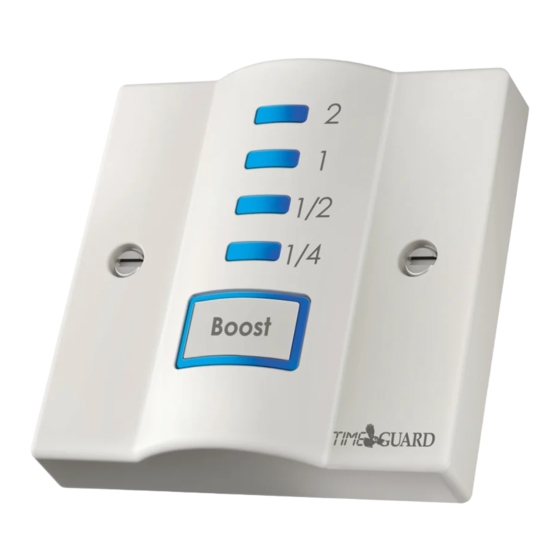
1. General Information
Boost time LED's
2
1
1/2
1/4
Boost
Boost Button
Fig. 1
TGBT4 Front Panel
1
Contents
1
TGBT4 Boostmaster.
2
3.5mm screws.
1
Bag containing: 2 screws, cable blank and cable clamp.
1
Instruction leaflet.
The TGBT4 is a boost timer giving a range of boost times from
1/4hr to 2hrs covering the majority of requirements for heating,
ventilation and lighting (a light switch may be replaced by this unit
if a neutral is available).
The unit fits on a single gang wall box, flush or surface, 25mm deep
and above.
It can be instantly cancelled or reset and the 1/4hr LED flashes a
warning of time out.
A blanking plate can be removed to allow an appliance cord to outlet
from the lower front.
2. Installation
Neutral out
Neutral in
Fig. 2
TGBT4 Rear Connections
2
The unit is designed to replace an existing single gang connection
unit, socket outlet or fixed appliance outlet. The unit is capable of
forming part of a ring main (the terminals can accept 2 x 2.5mm sq.
cables) or terminating a spur off the ring main. The unit requires a
minimum depth of 25mm within the box.
Ensure that the wiring is adequate for the load to be carried. Connect
incoming and outgoing cables to the relevant terminals. Secure the
unit to the back box with the 3.5mm screws provided forming the
cables during installation to avoid entrapment and cable damage.
Use the earth terminal in the back box for earth continuity if required.
If installed into a metal back box, earthing of the back box is
required.
There is a removable cable blank to cover the front cable exit if this
feature is not required. If front exiting cable is required use the cable
clamp supplied to secure the outgoing cable.
3. Operation
The required boost time is selected by pressing the button marked
Boost repeatedly. The LED's adjacent to the time markers (above the
Live out
Boost button) will light up in the sequence:-
First push gives 1/4hr boost
Second push gives 1/2hr boost
Third push gives 1hr boost
Live in
Fourth push gives 2hr boost
Fifth push returns to zero boost (all LED's out)
Once the boost selected is underway the LED's will go out sequentially
indicating the approximate boost time remaining. The LED which is
Cord grip/
about to go out will flash when there is less than 2 minutes remaining
blanking plate
fixing screw
of that period.
holes
Example:- 2hr boost has been set.
After 1hr the 2hr LED will go out indicating 1hr remaining.
3
After a further 1/2hr the 1hr LED will go out indicating 1/2hr remaining.
After a further 1/4hr the 1/2hr LED will go out indicating 1/4hr
remaining.
In this way the user has an approximate guide to the remaining
duration of the boost.
Stopping or Increasing Boost
If it is less than 15 seconds since the Boost button was pressed the
boost may be stopped at any time by pressing the Boost button
repeatedly until all the LED's are extinguished. After 15 seconds the
boost may be stopped by a single press of the Boost button.
The boost period may be changed at any time by pressing the Boost
button until the required time LED is lit. In which case the indicated
boost time will start from when the Boost button was pressed.
If the button is pressed and then held the LED's will cycle upwards
with 1 second between each change. It will go in the sequence 1/4,
1/2, 1, 2, OFF, 1/4, 1/2 etc.
(LED opposite 1/4 is on)
(LED's opposite 1/4 and 1/2 are on)
(LED's opposite 1/4, 1/2 and 1 are on)
(LED's opposite 1/4, 1/2, 1 and 2 are on)
Advertisement

Related Manuals for Theben TIME GUARD TGBT4


Summary of Contents for Theben TIME GUARD TGBT4
- Page 1 1. General Information 2. Installation 3. Operation The required boost time is selected by pressing the button marked Boost time LED’s Boost repeatedly. The LED’s adjacent to the time markers (above the Live out Boost button) will light up in the sequence:- First push gives 1/4hr boost (LED opposite 1/4 is on) Second push gives 1/2hr boost...
- Page 2 4. Specifications This product complies with: LVD Directive 72/23/EEC. Electronic EMC Directive 89/336/EEC. In the unlikely event of this product becoming faulty due to defective material or manufacture, within 3 years of the date of purchase, please and relevant clauses of the following standards: BS EN 60730-7-2:1992;...
Need help?
Do you have a question about the TIME GUARD TGBT4 and is the answer not in the manual?
Questions and answers