Table of Contents
Advertisement
Quick Links
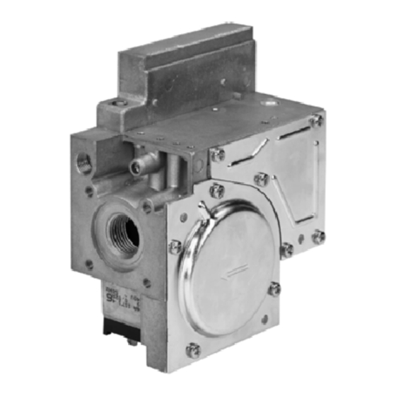
DUAL VALVE ASSEMBLY APPLICABLE FOR BUILT--ON PURPOSES
DESCRIPTON
The VR4920Z 1000 dual valve has been specially developed
to have kits fit--on.
When a kit with a V7335A electric modulating regulator
(Modureg) is fitted on the dual valve assembly the type gas
control is equal to a VR4920M.
When a kit with a V4336A electric high low regulator is fitted
on the dual valve assembly the gas control is equal to a
VR4920P.
APPLICATION
The VR4920M provides the following functions:
Servo pressure regulation
Outlet pressure is held at a constant value regardless of
fluctuations of inlet pressure.
Modulating control
Between minimum and maximum outlet pressure gas
supply to the appliance is dependent on the electrical
signal to modulating coil.
Mechanical limitation of outlet pressure
The minimum and maximum burner pressures are
mechanically adjusted to guarantee good burner
performance in case the modulating control should
become out of range.
The VR4920M is designed to work together with the W9335
modulating Modureg control, W4115 logic control, T7335A
thermistor temperature sensor and an advanced range of
micro computer based modulating controls.
VR4920Z 1000 AND 45.900.449-
The VR4920P provides the following functions:
Servo pressure regulation
Outlet pressure is held at a constant value regardless of
fluctuations of inlet pressure.
High- -Low control
Within the ranges specified a high and a low outlet
pressure can be mechanically adjusted and electrically
selected.
High outlet pressure to appliance will be established by
switching control voltage to High--Low coil on.
By switching voltage off, outlet pressure will drop to low
pressure setting.
INSTRUCTION SHEET
6 Adjust Modureg or
High--Low setting
5 Make soudness testing
4 Fit Modureg or High--Low
regulator with the indent
beside the locating plug and
fix with the two screws
provided.
3 Place seal
2 Fix operator with the four
screws provided
1 Place gasket
note: orientation !!!
Fig. 1.
EN1R--9181 0104R1--NE
Advertisement
Table of Contents

Related Manuals for Honeywell VR4920Z 1000


Summary of Contents for Honeywell VR4920Z 1000
- Page 1 High--Low setting DESCRIPTON 5 Make soudness testing 4 Fit Modureg or High--Low The VR4920Z 1000 dual valve has been specially developed regulator with the indent to have kits fit--on. beside the locating plug and When a kit with a V7335A electric modulating regulator...
- Page 2 A -- Inlet B -- Outlet C -- Inlet pressure tap D -- Outlet pressure tap E -- 6.3 mm terminals G -- Mounting holes (M5) for connecting flanges H -- Earth screw K -- Pilot outlet connection L -- Pilot flow adjustment screw M -- Optional for inlet pressure tap 1/8”BSPT Fig.
- Page 3 HOW TO CREATE THE DIFFERENT SPECIFICATIONS VR4920M FINAL O.S. NUMBERS Model VR4920M: line voltage gas control, fast opening with electric As mentioned in the description the VR4920Z1000 is special modulating regulator V7335A developed to have kits fit on it. Ambient temperature There are 5 different kits to order, with these 5 kits and valve 0 ...
- Page 4 Table 1. Regulator outlet pressure range V7335A Pressure range Color of cap Setting (mbar) (mbar) Minimum outlet pressure range Maximum outlet pressure range (mbar) (mbar) Sidewards Upwards 1.5 ... 20 grey 1.5 ... 15 2 ... 15 (min setting + 3) ... 20 3 ...
- Page 5 Adjusting minimum pressure setting (see fig. 3.) Checkout Connect a suitable pressure gauge to pipe line or to outlet After any adjustment, set appliance in operation and observe pressure tap of gas control concerned, to measure burner through a complete cycle to ensure that burner system pressure (measuring point must be as near to burner as components function correctly.
- Page 6 ADJUSTMENT AND CHECKOUT The High--Low is provided with an earth terminal. The High--Low is provided with quick connect terminals which VR4920P are suitable for 6.3 mm ( ”) receptacles (e.g.series “250” fasteners). IMPORTANT Also mPm type 122 connectors are to be used. Ordernumber: .
- Page 7 Adjusting minimum pressure setting (see fig. 4. page 6) Maintenance and service Connect a suitable pressure gauge to pipe line or to outlet Under normal circumstances no maintenance or service is pressure tap of gas control concerned, to measure burner required.
- Page 8 Home and Building Control Combustion Controls Center Europe Honeywell BV Phileas Foggstraat 7 7821 AJ Emmen The Netherlands Tel: +31 (- - )591 695911 Fax: +31 (- - )591 695200 http://europe.hbc.honeywell.com EN1R- -9181 0104R1- -NE...
Need help?
Do you have a question about the VR4920Z 1000 and is the answer not in the manual?
Questions and answers