Table of Contents
Advertisement
Quick Links
TRANSLATION OF THE ORIGINAL VERSION
OPERATION MANUAL
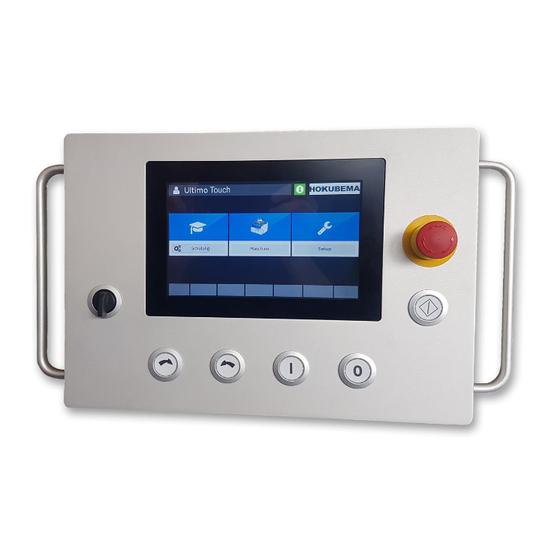
Ultimo-Touch 300
Four-Axis Touchscreen Control for Swivel Milling Machines
Usable for the machine types 245|100, 245|200 and 245|300
Operating instructions for the user level „machine operator"
•
Four-axis touchscreen control for connection to the Modbus TCP network
•
Program memory with up to 500 tools with each 100 program blocks
•
Positioning of height and swivel adjustment, milling fence, total fence
and partial fence (right)
•
With clear and intuitively operable surface
E-Mail:
info@hokubema-panhans.de
HOKUBEMA Maschinenbau GmbH
Graf-Stauffenberg-Kaserne, Binger Str. 28 | Halle 120
DE 72488 Sigmaringen | Tel. +49 07571 755-0
| Web:
https://hokubema-panhans.de
Advertisement
Table of Contents

Subscribe to Our Youtube Channel
Related Manuals for PANHANS Ultimo-Touch 300


Summary of Contents for PANHANS Ultimo-Touch 300
- Page 1 TRANSLATION OF THE ORIGINAL VERSION OPERATION MANUAL Ultimo-Touch 300 Four-Axis Touchscreen Control for Swivel Milling Machines Usable for the machine types 245|100, 245|200 and 245|300 Operating instructions for the user level „machine operator“ • Four-axis touchscreen control for connection to the Modbus TCP network •...
-
Page 2: Table Of Contents
Table of Contents General Information ........................5 Front Switches and Push-Buttons ....................5 Menu Icon Overview ........................6 Start Screen ............................. 7 Machine Access (only with option TM300) ..................8 User registration ........................8 Machine access in the absence of instruction ................ 9 Positioning ............................. - Page 3 Create a Program for a Tool ....................25 10.4.1 Load program ........................ 27 Handwheel for Fence Type 301 - Commissioning ..............28 WuT Com Server ++ ....................... 28 11.1.1 DIP Switch Settings ......................28 11.1.2 IP Settings ........................28 11.1.3 Bus Settings ........................
- Page 4 Figure 37: Serial parameter settings 3 ....................32 Figure 38: Save serial parameters ......................32 Figure 39: Com server logout ........................ 32 Figure 40: save configuration ........................ 32 Revisions: Revision Editor Modifications Date Original version translated / document created 2018-11-21 section 6.3 (Stop System 301) and chapter 10 (handwheel) added 2019-03-31 New fence types, chapter for additional indicator and screenshots with Eng-...
-
Page 5: General Information
1 General Information These operating instructions describe the functions of the "UT-300" touchscreen control that can be used for swivel milling machines of types 245 | 100, 245 | 200 and 245 | 300. Remark: This manual only describes the functions for the user level of a machine operator. Fur- ther resp. -
Page 6: Menu Icon Overview
3 Menu Icon Overview Depending on the mask, different menu icons appear for the required functions. This compact overview and describes the functions of the menu icons: Action Function Tap the Hokubema logo to display the current time instead of the logo. Touching the Hokubema logo again returns the window to the logo view. -
Page 7: Start Screen
4 Start Screen If the machine is not equipped with option TM-300 (see chapter 5), the following screen appears as start screen after switching on the controller: Figure 1: Start Screen The screen contains three buttons: Button Function The official machine instructions of the employers' liability insurance association Training with all safety-relevant information and instructions can be viewed here. -
Page 8: Machine Access (Only With Option Tm300)
5 Machine Access (only with option TM300) User registration In order to work with the UT-300 Ultimo-Touch controller and the machine, the user must first au- thorize himself with the RFID key assigned to him. Figure 2: Machine access: no key Once the appropriate RFID key has been inserted into the RFID reader, the user name appears in the upper left corner of the operator surface (see Figure 3): Figure 3: Machine access: username... -
Page 9: Machine Access In The Absence Of Instruction
Machine access in the absence of instruction Completed and upcoming trainings and annual machine instructions are stored in the system's data- base. If the target date for the next training resp. instruction has been exceeded, the username on the start screen is highlighted with a red background: Figure 4: Machine access: Training time exceeded As soon as the "Machine"... -
Page 10: Positioning
6 Positioning For safety reasons, the axes are positioned according to the "Hold to Run" principle, which means that the axes are not positioned simultaneously but one after the other - so that always only one axis can be in motion. Positioning sequence The positioning sequence is the same for all moving axes (see chapter ... -
Page 11: Machine Fences
7 Machine Fences Different types of fences are used depending on the machine type: Fence 302 (Machine Type 245/100 and 245/200) With this type, the total and partial fence must be adjusted manually. For adjustment, two hand lever screws are loosened, and the fence is adjusted by means of a hand wheel. If the fence has been positioned at the desired position, the two hand lever screws must be tightened again. -
Page 12: How To Change The Battery
7.4.3 How to change the battery Failure of the position indicator Improper installation leads to loss of protection class. • Tighten screws evenly until the battery unit is completely at the stop with the housing • Check the correct position of the O-ring Preparation: 1. -
Page 13: Setup Menu (Only For Machines Without Optional Access Control)
8 Setup Menu (only for machines without optional access control) When starting a machine without optional machine access control, the additional field “Setup” appears. On machines with optional machine access control, the master key must be inserted to enable the setup menu. Figure 8: Main screen with "Setup menu”... -
Page 14: Positioning Parameters
9 Positioning Parameters Speed To specify the rotary speed of the milling cutter in the range from 1,500 to 10,000 rpm: Figure 10: Speed setting for milling cutter Action Function Confirmation of the setting Start milling cutter at new speed ("Switch on milling cutter" button) Remark: When the spindle is rotating, the speed can only be corrected downwards! The nominal speed specified when starting the spindle is defined as the "Software Limit"... -
Page 15: Height Offset
Height Offset Input of the effective height (incl. calculation of the tool, etc.) in the range from 0 to 125 mm: Figure 12: Effective height (incremental) The setting range depends on the inserted tool and is also calculated accordingly (see display "min" and "max"). Action Function →... -
Page 16: Height Abs
Height Abs Setting of the absolute height in the range from 0 to 125: Figure 13: Absolute height Action Function → Confirmation of input + positioning enable The positioning button flashes BA_PH_UT300_EN_18-21.docx... -
Page 17: Angle
Angle The adjustment of the swivel angle for the milling spindle is made in this mask. The possible swivel range of the milling spindle is ± 45.5°. Figure 14: Swivel angle for the milling spindle Action Function → Confirmation of input + positioning enable The positioning button flashes BA_PH_UT300_EN_18-21.docx... -
Page 18: Fence Abs
Fence Abs This mask is used to enter the absolute fence position in mm. In addition, the compensation dimension for the partial fence can be set here: Figure 15: Absolute fence Action Function → Confirmation of input + positioning enable The positioning button flashes Set axis to 0 (Reset) -
Page 19: Fence Inc
Fence Inc This mask is used to enter an incremental fence position in mm: Figure 16: Incremental fence Action Function → Confirmation of input + positioning enable The positioning button flashes Switch to absolute mode "Fence Abs” Swivel-away devices: see section BA_PH_UT300_EN_18-21.docx... -
Page 20: Swivel-Away Devices (Option)
Swivel-away Devices (Option) 9.7.1 Fence Types 302, 311 and 320 The button in the masks "Fence Abs" and "Fence Inc" is used for the swivel-away devices: Pressing this button releases the clamping motors of the fence for the milling plate (only for fence type 320). -
Page 21: Machine Parameters
10 Machine Parameters After opening the machine parameters by using the "Machine" button, the following screen appears: Figure 18: Main menu of machine parameters The six blue main buttons can be used to make the respective settings. This mask also serves as an overview of all adjustable machine parameters during regular operation. -
Page 22: List Of Tools
List of Tools After selecting the "Tools" button, an overview of all existing tools appears. Note: If no tools have yet been created, this list is empty. Figure 19: Tool overview Action Function With this button a new tool can be created. Manual mode: Discards all loaded tool and program parameters. -
Page 23: Create A Tool
Create a Tool Up to 500 tools can be stored in the program memory of the UT-300 unit. Select to create a new tool: Figure 20: Creating a tool Fill in all relevant fields (see table below) by tapping in the respective column one after the other and finally confirm the entries with "Enter". -
Page 24: Edit An Existing Tool
Edit an Existing Tool To edit an existing tool, go to the tool list and select the line of the tool to be changed. This line is now highlighted in light blue: Figure 21: Edit an existing tool / select line Then press the button and change the desired parameters by overwriting them with the new values. -
Page 25: Create A Program For A Tool
Create a Program for a Tool The UT-300 control allows you to assign up to 100 different programs to each existing tool. In a pro- gram the parameters Speed, Angle, Height, Fence, Partial Fence as well as the Reference point of the tool “Datum”... -
Page 26: Figure 24: Program Settings For Tool
The name of the program and all relevant parameters can be entered in the now appearing mask: Figure 24: Program settings for tool The "Program No." is assigned automatically (in ascending order). The "Tool Type" is not editable be- cause it has already been selected before. Now use the corresponding fields and enter a unique name in the "Name"... -
Page 27: Load Program
Figure 26: Program list with a stored program 10.4.1 Load program To load a stored program from the program list into the machine, mark the corresponding program line by touching it so that it is highlighted in light blue. Then press to accept the program. -
Page 28: Handwheel For Fence Type 301 - Commissioning
Handwheel for Fence Type 301 - Commissioning WuT Com Server ++ 11.1.1 DIP Switch Settings Open the Com-Server and set the following sequence (RS485 2-wire): Figure 27: DIP switch settings 11.1.2 IP Settings Set the Service PC as follows: IP Address: 192.168.115.23 Subnet: 255.255.255.0... -
Page 29: Figure 29: Open Network Parameters
Click with the right mouse button on the corresponding Com-Server and select the menu item "Set Network Parameters". Figure 29: Open network parameters Enter the following values: Figure 30: Set network parameters Press "Next" to upload the settings to the Com-Server. BA_PH_UT300_EN_18-21.docx... -
Page 30: Bus Settings
→ The server restarts … Figure 31: Server restart 11.1.3 Bus Settings After restarting the Com-Server, it should appear in the WuTility software with the correct IP ad- dress. If this is not the case, scan the devices again. Figure 32: Perform a new scan Double-click on the selected line to access the WuT Com Server Web interface. -
Page 31: Figure 34: Open Serial Parameters
Figure 34: Open serial parameters Now click on the menu item "SETUP Port 0 (Serial)" to reach the parameter level of the serial inter- face. In the following menu click on "UART Setup" to configure the serial interface. The following parameters must be set: Figure 35: Serial parameter settings 1 Figure 36: Serial parameter settings 2 BA_PH_UT300_EN_18-21.docx... - Page 32 Figure 37: Serial parameter settings 3 Finally click on "Send" to send the parameters to the Com-Server. PLEASE NOTE: The settings are not yet stored in the non-volatile memory. To save the parameters, proceed as follows: Figure 38: Save serial parameters Click "Back"...
Need help?
Do you have a question about the Ultimo-Touch 300 and is the answer not in the manual?
Questions and answers