Table of Contents
Advertisement
Quick Links
TRANSLATION OF THE ORIGINAL VERSION
OPERATION MANUAL
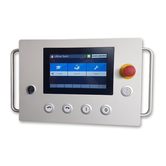
Ultimo-Touch 300
Four-Axis Touchscreen Control for Tilting Spindle Moulders
Usable for the Machine Versions 245|100, 245|200 and 245|300
Operating instructions for the user level "Machine Operator"
•
Four-axis touchscreen control for connection to the Modbus TCP network
•
Program memory with up to 500 tools with each 100 program blocks
•
Positioning of height and swivel adjustment, milling fence, total fence
and partial fence (right)
•
With clear and intuitively operable surface
E-Mail:
info@hokubema-panhans.de
HOKUBEMA Maschinenbau GmbH
Graf-Stauffenberg-Kaserne, Binger Str. 28 | Halle 120
DE 72488 Sigmaringen | Tel. +49 07571 755-0
| Web:
https://hokubema-panhans.de
Advertisement
Table of Contents

Subscribe to Our Youtube Channel
Related Manuals for PANHANS Ultimo-Touch 300

Summary of Contents for PANHANS Ultimo-Touch 300
- Page 1 TRANSLATION OF THE ORIGINAL VERSION OPERATION MANUAL Ultimo-Touch 300 Four-Axis Touchscreen Control for Tilting Spindle Moulders Usable for the Machine Versions 245|100, 245|200 and 245|300 Operating instructions for the user level “Machine Operator” • Four-axis touchscreen control for connection to the Modbus TCP network •...
-
Page 2: Table Of Contents
Table of Contents General Information ........................5 Legal Notice ..........................5 Illustrations ..........................5 Front Switches and Push Buttons ....................5 Menu Button Overview ........................6 Start Screen ............................. 7 Machine Access (only with option TM300) ..................8 User registration ........................8 Machine access in the absence of instruction ................ - Page 3 10.5.1 Fence Type 320 (Absolute) .................... 24 10.5.2 Fence Type 320 (Incremental) ..................25 Swivel-away Devices (Option) ....................26 10.6.1 Fence Types 301, 302, 311 and 320 ................26 10.6.2 Remove Fence Type 320 without Swivel-away Device ..........26 Tools and Program Memory ...................... 27 List of Tools ..........................
- Page 4 List of Figures Figure 1: Start Screen .............................. 7 Figure 2: Machine access: no key ..........................8 Figure 3: Machine access: username ........................8 Figure 4: Machine access: Training time exceeded ....................9 Figure 5: Warning message "Overdue Instruction" ....................9 Figure 6: Coloured background of the actual values.....................
-
Page 5: General Information
General Information These operating instructions describe the functions of the "UT-300" touchscreen control that can be used for Tilting Spindle Moulders of types 245|100, 245|200 and 245|300. Remark: This manual only describes the functions for the user level of a machine operator. -
Page 6: Menu Button Overview
Menu Button Overview Depending on the mask, different menu buttons appear for the required functions. The following overview describes the functions of the menu buttons: Button Function Tap the Hokubema logo to display the current time instead of the logo. Touching the Hokubema logo again returns the window to the logo view. -
Page 7: Start Screen
Start Screen If the machine is not equipped with an optional Machine Access Control “TM-300” (see chapter 5), the following screen appears as start screen after switching on the controller: Figure 1: Start Screen The screen contains three buttons: Button Function The official machine instructions of the German employers' liability insurance asso-... -
Page 8: Machine Access (Only With Option Tm300)
Machine Access (only with option TM300) User registration In order to work with the UT-300 Ultimo-Touch controller and the machine, the user must first au- thorize himself with the RFID key assigned to him. Figure 2: Machine access: no key Once the appropriate RFID key has been inserted into the RFID reader, the user name appears in the upper left corner of the operator surface (see Figure 3): Figure 3: Machine access: username... -
Page 9: Machine Access In The Absence Of Instruction
Machine access in the absence of instruction Completed and upcoming trainings and annual machine instructions are stored in the system's data- base. If the target date for the next training resp. instruction has been exceeded, the username on the start screen is highlighted with a red background: Figure 4: Machine access: Training time exceeded As soon as the "Machine"... -
Page 10: General Information On Axis Positioning
General Information on Axis Positioning For safety reasons, the axes are positioned according to the "Hold to Run" principle, which means that the axes are not positioned simultaneously but one after the other - so that always only one axis can be in motion. -
Page 11: Machine Overview
Machine Overview After pressing the "Machine" button, the following screen appears: Figure 7: Machine overview mask with tools, axis positions and speed (example 245|300) The six blue main buttons are used to make the respective settings. This mask also serves as an over- view of all adjustable machine settings during regular operation. -
Page 12: Speed Settings
Speed Settings Speed Setting with Types 245|200 and 245|300 in the machine overview (see chapter 7), the screen shown below After tapping the symbol appears. Here the rotary speed of the cutter can be set in the range from 1,500 to 10,000 rpm: Figure 8: Speed setting for milling cutter Action Function... -
Page 13: Height And Angle Positioning
Height and Angle Positioning Height (Offset) Input of the effective height (incl. calculation of the tool, etc.) in the range from 0 to 125 mm: Figure 11: Effective height (incremental) The setting range depends on the inserted tool and is also calculated accordingly (see display "min"... -
Page 14: 9.1.2 Calibrate The Tool Height With The Zeromaster
9.1.2 Calibrate the Tool Height with the Zeromaster Before calibrating with Zeromaster, make sure that the tool angle is set exactly to 0°! Before placing the Zeromaster connected to the machine, the table surface of the machine must be cleaned of dirt, chips and any objects must be removed from the table. Chips and dirt between the Zeromaster and the table surface will falsify the calibration value! Figure 12: Calibrate the tool height with the Zeromaster 1. -
Page 15: Height (Absolute)
Height (Absolute) Setting of the absolute height in the range from 0 to 125 mm: Figure 13: Absolute height Action Function → Confirmation of input + positioning enable The positioning button flashes Move height in manual inching mode (1/10 mm steps) BA_PH_UT300_EN_08-22.docx... -
Page 16: Angle
Angle The adjustment of the swivel angle for the milling spindle is made in this mask. • The possible swivel range of the milling spindle for versions 245|200 and 300 is ± 45.5°. • For the version 245|100, the standard range is -5° to +45.5° (optional ± 45.5°). Figure 14: Swivel angle for the milling spindle Action Function... -
Page 17: Fence Positioning
Fence Positioning Depending on the machine type and equipment, different fence types are used: • Type 301 (standard for machine versions 245|100 and 245|200). → Total fence and partial fence is manually adjustable. • Type 302 (option for machine versions 245|100 and 245|200) →... -
Page 18: Fence Type 301 (Incremental)
10.1.2 Fence Type 301 (Incremental) Switching to the incremental window is done via the button on the handwheel. Figure 16: Fence Type 301 (Incremental) • The mask is used to read the incremental position of the total fence. • It is not possible to specify a target value here. •... -
Page 19: Fence 302
Fence 302 10.2.1 Fence Type 302 (Absolute) With this type, the total fence and the partial fence must be adjusted manually. Before adjustment via handwheel, two hand lever screws must be loosened. After adjustment, the two hand lever screws must be tightened again. Total fence as well as partial fence are each equipped with an indicator on the handwheel and can be read simultaneously on the UT-300 touchscreen controller. -
Page 20: Fence Type 302 (Incremental)
10.2.2 Fence Type 302 (Incremental) Switching to the incremental window is done via the button on the handwheel. Figure 18: Fence Type 302 (Incremental) • No target value setting possible for the total fence in incremental measurement mode. • In order to be able to compensate for the chip removal also in incremental mode, a target value for the partial fence can be entered in the "Part"... -
Page 21: Calibration Value "Spindle Type" For Fences 301 And 302
Calibration Value “Spindle Type” for Fences 301 and 302 (from Software Version 3.9.2.5) With this new function it is possible to select the spindle type used and to transmit half the spindle diameter as a calibration value to the handwheel of the fence types 301 and 302. Figure 19: Spindle selection button •... -
Page 22: Fence 311
Fence 311 10.4.1 Fence Type 311 (Absolute) With this type, the total fence can be automatically adjusted and the partial fence manually. Before adjustment, both clamping levers must be released. The total fence can then be positioned automati- cally. Once the stop has been positioned at the setpoint, the two clamping levers must be tightened again. -
Page 23: Fence Type 311 (Incremental)
10.4.2 Fence Type 311 (Incremental) Figure 21: Fence Type 311 (Incremental) • The mask is used to set the target value of the total fence position in incremental mode. • After entering the target value and confirming with , the positioning button flashes. When the positioning button is pressed, the positioning for the total fence is performed automatically, and the current position can be read in the "Actual:"... -
Page 24: Fence 320
Fence 320 With Type 320, the total fence as well as the partial fence can be automatically adjusted and are each clamped electromechanically. To lift the fence, two screws must be loosened and removed manually. 10.5.1 Fence Type 320 (Absolute) Figure 22: Fence Type 320 (Absolute) •... -
Page 25: Fence Type 320 (Incremental)
10.5.2 Fence Type 320 (Incremental) This mask is used to enter an incremental fence position in mm: Figure 23: Fence Type 320 (Incremental) • The mask is used to set the target value of the total fence position in incremental mode. •... -
Page 26: Swivel-Away Devices (Option)
Swivel-away Devices (Option) 10.6.1 Fence Types 301, 302, 311 and 320 The button in the masks "Fence Abs" and "Fence Inc" is used for the swivel-away devices: Press- ing this button releases the clamping motors of the fence for the milling plate (only for fence type 320). Then the message “Remove clamping levers"... -
Page 27: Tools And Program Memory
Tools and Program Memory Touching the "Tools" button opens the tool and program memory: Figure 25: Open the tool and program memory in the machine overview Action Function Digital clipboard: Displays all details for a selected program (for details refer to section List of Tools After selecting the "Tools"... -
Page 28: Create A Tool
Manual mode: Discards all loaded tool and program parameters. The machine no longer 6.3 calculates any values and the selected axis can be moved manually (refer to Create a Tool Up to 500 tools can be stored in the program memory of the UT-300 unit. Select to create a new tool: Figure 27: Creating a tool... -
Page 29: Edit An Existing Tool
Edit an Existing Tool To edit an existing tool, go to the tool list and select the line of the tool to be changed. This line is now highlighted in light blue: Figure 28: Edit an existing tool / select line Then press the button and change the desired parameters by overwriting them with the new values. -
Page 30: Create A Program For A Tool
Create a Program for a Tool The UT-300 control allows you to assign up to 100 different programs to each existing tool. In a pro- gram the parameters Speed, Angle, Height, Fence, Partial Fence as well as the Reference point of the tool “Reference Point”... -
Page 31: Figure 30: Program Settings For Tool
The name of the program and all relevant parameters can be entered in the now appearing mask: Figure 31: Program settings for tool The "Program No. " is assigned automatically and can be renamed if required. The "Tool Type" is not editable because it has already been selected before. -
Page 32: 11.4.1 Load Program
After saving, the screen changes to the program list, where the newly created program is listed : Figure 33: Program list with a stored program 11.4.1 Load program To load a stored program from the program list into the machine, mark the corresponding program line by touching it so that it is highlighted in light blue. -
Page 33: Correct Loaded Program
Correct loaded Program In some cases it may be necessary to correct specific settings of a loaded program after a trial milling. As soon as any value of the currently loaded program is changed, a small symbol (see Figure 35) appears next to the tool designation in the machine overview. -
Page 34: Info Window With Status Messages
Info Window with Status Messages Tapping the symbol opens the info window with relevant status messages, information about the machine, connected hardware and the I/Os: Figure 38: Info window with status messages The info symbol serves additionally to signal the operational readiness: Colour Meaning →... -
Page 35: Setup Menu (Without Machine Access Control Tm 300)
Setup Menu (without Machine Access Control TM 300) When starting a machine without optional machine access control, the additional field “Setup” appears. On machines with optional machine access control, the master key must be inserted to enable the setup menu. Figure 39: Main screen with "Setup menu”... -
Page 36: Error Messages And Troubleshooting
Error Messages and Troubleshooting Depending on the machine model and fence type, different error messages appear when a malfunc- tion occurs or due to safety-relevant aspects. The following overview table shows all error numbers and the corresponding page number. • Clicking on the error number or using the indicated page number will take you directly to the corresponding error description with the cause and how you can remedy the fault. - Page 37 Cause: Frequency inverter went into collective Collective Fault fault. Error may have been reset automati- [U0001] Frequency Inverter cally. Error code is supplemented with the Code: error number of the frequency inverter. • Restart the machine. If this is not success- Remedy: ful, contact customer service and inform them of the FI error number.
- Page 38 Cause: 245|100 only: When the spindle start button Brake Released is pressed, the "Release Brake" switch on the [E0004] Selector switch "Brake Release" "Eaton Easy" control module is queried. is active!! • Deactivate the brake release switch. Remedy: Cause: Malfunction at the machine socket. Motor Protection F2 Error •...
- Page 39 Cause: Error when processing a bus request to the Modbus Slave Error 3-axis controller. [E0009] BK 3-axis controller • Contact customer service Remedy: Cause: An error on the bus was intercepted. Modbus Exception • Contact customer service Remedy: [E0010] BK 3-axis controller An error occurred when pausing between Cause: Bus Pause Error...
- Page 40 Error while processing a bus request to the Cause: Modbus Slave Error TM 300 Reader. [E0015] TM System • Contact customer service Remedy: Cause: An error on the bus was intercepted. Modbus Exception • Contact customer service Remedy: [E0016] TM System Cause: Faulty input or output on the bus.
- Page 41 An attempt was made to access an invalid Cause: Modbus Protocol Error address or the participant cannot process [E0021] Total fence controller the request. • Contact customer service Remedy: An error occurred when pausing between Cause: Bus Pause Error two bus queries. [E0022] Total fence controller •...
- Page 42 An error occurred when pausing between Cause: Bus Pause Error two bus queries. [E0027] Partial fence controller • Check wiring between Remedy: controller and switch An error that cannot be assigned and should Cause: Bus Exception Error not actually occur. [E0028] Partial fence controller •...
- Page 43 An error that cannot be assigned and should Cause: Bus Exception Error not actually occur. [E0033] SDC Light Speed Monitor • Contact customer service Remedy: Error when processing a bus request to the Cause: Modbus Slave Error frequency inverter. [E0034] Frequency Inverter •...
- Page 44 An error that cannot be assigned and should Cause: Bus Exception Error not actually occur. [E0038] Frequency Inverter • Check wiring between FI and switch Remedy: • Check proper fit of COM extension to FI Work on the FI only by a qualified elec- trician! ATTENTION: The inverter can remain energised for up to 15 minutes after turning off the main switch!
- Page 45 • Die „Mainunit Prop.“ file is damaged! [T1002] • Contact customer service Remedy: An attempt was made to calibrate one of Cause: Service Level Error the axes to an invalid value (e.g. by entering [T0033] Incorrect value entered! invalid or double decimal characters). •...
- Page 46 Invalid value: The calculated, absolute Cause: Software End Limit height could not be transferred to the con- [T0039] Software end limit for troller. total fence was approached!! • Check target value Remedy: • Enter smaller value of the axis A transfer of the value for the height axis to Cause: Software End Limit the 3-axis controller was cancelled because...
- Page 47 When updating the move commands, it is Cause: Software End Limit checked again whether a target could lead [T0045] You are trying to to a collision. cross an end limit! • Check target value Remedy: • Enter smaller value of the axis Graphics of the training are loaded concur- Cause: Touchscreen Error...
- Page 48 Cause: On model 245|100, the position of the belt Belt Pulley pulley is checked after loading a program. [S0001] Observe speed! If this does not match the stored speed, the Please set the V- belt to 6000. message appears. • Set the V-belt to the speed indicated in Remedy: the error message.
Need help?
Do you have a question about the Ultimo-Touch 300 and is the answer not in the manual?
Questions and answers