Table of Contents
Advertisement
Quick Links
Advertisement
Table of Contents

Summary of Contents for gfm GF-16
- Page 1 Grip Factory Munich YOUR INNOVATIVE PARTNER FOR CAMERA SUPPORT GF-16 Crane System Instruction Manual Valid: March 2015 Grip Factory Munich GmbH Tel.: +49 (0) 89 319 0 129-0 Fürholzener Straße 1 Fax: +49 (0) 89 319 0 129-9 85386 Eching bei München e-Mail: info@g-f-m.net...
-
Page 2: Table Of Contents
Positioning the Adjustable Mounting Column ............45 GF-16 Camera Crane and Dolly Dimensions ............46 Dolly weight ........................ 46 Accessories for GF-16 Crane platform weight list ............47 Transport trolley for the GF-16 Crane ................. 48 Maintaining the Adjustable Column ................49 Dismantling the column: .................... -
Page 3: Safety Guidelines
25km/h (15.6mph). For this purpose see page 44. The complete lift and panning range of the GF-16 Crane must be kept clear of obstructions at all times. A safety clearance of 1m / 3' 3" must be observed on all sides of the crane during operation. Only authorised, trained and experienced personnel are allowed to operate the crane. -
Page 4: Assembly Procedure - Gf-16
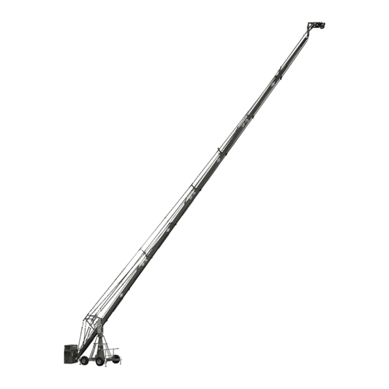
Assembly Procedure – GF-16 General description: The GF-16 is a mobile crane-system for mounting cameras in a stationary ground position or for movement on track. It can be operated manually from the ground and can be panned in all directions either with a remote-bracket or a 1 to 2 person platform. -
Page 5: The Gf-16 Adjustable Mounting Column
GF-16 Crane System Instruction Manual The GF-16 Adjustable Mounting Column: Bolt the Adjustable Mounting Column to the base dolly. Make sure that the locking bolts are locked securely. Tip: The carrying handles on the bazooka should point to the left and right of the dolly. -
Page 6: Pivot Section
GF-16 Crane System Instruction Manual Pivot Section Located on the middle section are 2 tilt friction locks which may be used to lock the tilt during set-up. Set the pivot arm at 90° to the centre post and lock the friction locks which can be found on the left and right hand side of the middle section. - Page 7 Tip: To mount the top bucket just put it on top of the lower one and screw it either with the provided safety pins or the captive screws. (See the GF-16 Specifications at which version the Top Bucket is needed)
-
Page 8: Version 1
GF-16 Crane System Instruction Manual Version 1 1 x 200 cm / 6' 6” Front extension arms required 1 x 192 cm / 6' 3” Rear extension arm required 420 cm / 13’ 9” Lift range 423 cm / 13’ 10”' Maximum Euro-adapter height Lift capacity (working load) 2 pers. -
Page 9: Version 2
GF-16 Crane System Instruction Manual Version 2 1 x 200 cm / 6' 6” + 1 x 100 cm / 3’ 3” Front extension arms required 1 x 192 cm / 6' 3” Rear extension arm required 575 cm / 18’ 10”... -
Page 10: Rigging System
GF-16 Crane System Instruction Manual Rigging system The rigging system must be used from Version 3 upwards. General: For versions using more than 3 x 200cm long sections (versions 7 to 15), a double rigging system must be mounted. During assembly, to support the arm and ensure that it does not dip, mount the lower rigging system as soon as crane arm sections 2, 3 or 4 (depending on version) are mounted. -
Page 11: Parallelogram Supports
GF-16 Crane System Instruction Manual assembled. For each extension arm, 1 rigging rod length consisting of 2 rods, is required. From Version 7 upwards, i.e. more than 3 extensions a double rigging system is required i.e. top and bottom. Top and lower rigging... -
Page 12: Version 3
GF-16 Crane System Instruction Manual Version 3 2 x 200 cm / 6' 6” Front extension arms required 1 x 192 cm / 6' 3” Rear extension arm required 734 cm / 24’ Lift range 581 cm / 19’ Maximum Euro-adapter height Lift capacity (working load) 2 pers. - Page 13 GF-16 Crane System Instruction Manual 21. Connect the last 2 standard rigging rods to the 2 rigging rod connectors on arm extension number 2. Ensure that the locking pins are inserted fully. 22. Hand tighten the rods by turning the turnbuckles until the rods are taut, then secure the turnbuckles with the locking nut as seen on page 9.
-
Page 14: Version 4
GF-16 Crane System Instruction Manual Version 4 2 x 200 cm / 6' 6” + 1 x 100 cm / 3’ 3” Front extension arms required 1 x 192 cm / 6' 3” Rear extension arm required 890 cm / 29’ 2”... - Page 15 GF-16 Crane System Instruction Manual 21. Connect 2 standard rigging rods to the turnbuckles on the front side of the rigging harness. Ensure that the locking pins are inserted fully. 22. Connect another 2 standard rigging rods to the first 2 standard rigging rods. Ensure that the locking pins are inserted fully.
-
Page 16: Version 5
GF-16 Crane System Instruction Manual Version 5 3 x 200 cm / 6' 6” Front extension arms required 1 x 192 cm / 6' 3” Rear extension arm required 1049 cm / 34’ 4” Lift range 738 cm / 24' 2”... - Page 17 GF-16 Crane System Instruction Manual 21. Connect another 2 standard rigging rods to the first 2 standard rigging rods. Ensure that the locking pins are inserted fully. 22. Connect a Rigging Rod Connector to each of the second Rigging Rods ensuring that the locking pins are inserted fully.
-
Page 18: Version 6
GF-16 Crane System Instruction Manual Version 6 3 x 200 cm / 6' 6” + 1 x 100 cm / 3’ 3” Front extension arms required 1 x 192 cm / 6' 3” Rear extension arm required 1205 cm / 39’ 6”... - Page 19 GF-16 Crane System Instruction Manual The “Rigging Harness Assembly” is described on page 9. After reading and following the instructions, please proceed as follows. 21. Connect 2 turnbuckles to the top connection on the front side of the rigging harness.
-
Page 20: Version 7
GF-16 Crane System Instruction Manual Version 7 4 x 200 cm / 6' 6” Front extension arms required 1 x 192 cm / 6' 3” Rear extension arm required 1364 cm / 44’ 9” Lift range 895 cm / 29' 4”... - Page 21 GF-16 Crane System Instruction Manual 22. Connect the angle adjuster to the end of the 200cm / 6’ 6” extension number 4. Release the angle adjuster by removing the safety pins from the side of the angle adjuster. Secure the angle adjuster to extension number 4 with a removed safety pin.
-
Page 22: Version 8
GF-16 Crane System Instruction Manual Version 8 4 x 200 cm / 6' 6” + 1 x 100 cm / 3’ 3” Front extension arms required 1 x 192 cm / 6' 3” Rear extension arm required 1519 cm / 49’ 10”... - Page 23 GF-16 Crane System Instruction Manual Note: Support the second and fourth parallelogram rod with the parallelogram supports located on sections 2 and 4 and secure with the locking pin as shown on page 10. 23. Connect the 100cm / 3’ 3” parallelogram rod to the last parallelogram connection and secure it with the provided safety pin.
-
Page 24: Version 9
GF-16 Crane System Instruction Manual Version 9 5 x 200 cm / 6' 6” Front extension arms required 1 x 192 cm / 6' 3” Rear extension arm required 1678 cm / 55’ Lift range 1053 cm / 34' 6”... - Page 25 GF-16 Crane System Instruction Manual 23. Connect the 200cm / 6’ 6” extension number 4 to extension number 3. Slip the connection flanges into each other and secure with the provided safety pin. 24. Connect the 200cm / 6’ 6” extension number 5 to extension number 4. Slip the connection flanges into each other and secure with the provided safety pin.
- Page 26 GF-16 Crane System Instruction Manual 41. Connect the platform to the angle adjuster and secure with the removed safety pin from the side of the angle adjuster. Ensure that the platform is level. Tip: The angle adjuster has an integrated leveller. By turning it, the vertical plate on the angle adjuster can be set to a perfect right angle.
- Page 27 GF-16 Crane System Instruction Manual Version 10 5 x 200 cm / 6' 6” + 1 x 100 cm / 3’ 3” Front extension arms required 1 x 192 cm / 6' 3” Rear extension arm required 1834 cm / 60’ 2”...
- Page 28 GF-16 Crane System Instruction Manual 23. Connect the 200cm / 6’ 6” extension number 4 to extension number 3. Slip the connection flanges into each other and secure with the provided safety pin. 24. Connect the 200cm / 6’ 6” extension number 5 to extension number 4. Slip the connection flanges into each other and secure with the provided safety pin.
- Page 29 GF-16 Crane System Instruction Manual straight line and should not bend or dip. 42. When the Rigging Rods are taut and running in a straight line, insert the locking pin connecting the Rigging Rod Connectors into the Rigging Support Brackets on section 2 and 4 as shown on page 10.
- Page 30 GF-16 Crane System Instruction Manual Version 11 6 x 200 cm / 6' 6” Front extension arms required 1 x 192 cm / 6' 3” Rear extension arm required 1954 cm / 64’ 1” Lift range 1217 cm / 39' 11”...
- Page 31 GF-16 Crane System Instruction Manual 23. Connect the 200cm / 6’ 6” extension number 4 to extension number 3. Slip the connection flanges into each other and secure with the provided safety pin. 24. Connect the 200cm / 6’ 6” extension number 5 to extension number 4. Slip the connection flanges into each other and secure with the provided safety pin.
- Page 32 GF-16 Crane System Instruction Manual 43. Remove the support stand or rostrum supporting the counterweight bucket section. 44. Then unlock the tilt friction. Before operation, all locking pins, locking screws etc should be inspected to ensure that all assembly sections are securely fastened.
- Page 33 GF-16 Crane System Instruction Manual Version 12 6 x 200 cm / 6' 6” + 1 x 100 cm / 3’ 3” Front extension arms required 1 x 192 cm / 6' 3” Rear extension arm required 2110 cm / 69’ 2”...
- Page 34 GF-16 Crane System Instruction Manual 24. Connect the 200cm / 6’ 6” extension number 5 to extension number 4. Slip the connection flanges into each other and secure with the provided safety pin. Note: Section 5 must be supported by a suitable support stand or rostrum.
- Page 35 GF-16 Crane System Instruction Manual 45. Hand tighten the rods by turning the turnbuckles until the rods are taut, then secure the turnbuckles with the locking nut as seen on page 9. Attention: The rigging system when taut as well as the crane arm, should run in a straight line and should not bend or dip.
- Page 36 GF-16 Crane System Instruction Manual Version 13 7 x 200 cm / 6' 6” Front extension arms required 1 x 192 cm / 6' 3” Rear extension arm required 2269 cm / 74’ 5” Lift range Maximum Euro-adapter height 1374 cm / 45'...
- Page 37 GF-16 Crane System Instruction Manual 23. Connect the 200cm / 6’ 6” extension number 4 to extension number 3. Slip the connection flanges into each other and secure with the provided safety pin. 24. Connect the 200cm / 6’ 6” extension number 5 to extension number 4. Slip the connection flanges into each other and secure with the provided safety pin.
- Page 38 GF-16 Crane System Instruction Manual 44. Connect 2 standard rigging rods to the Rigging Rod Connectors and in turn to the rigging connectors on section 6. Ensure that the locking pins are inserted fully. 45. Hand tighten the rods by turning the turnbuckles until the rods are taut, then secure the turnbuckles with the locking nut as seen on page 9.
- Page 39 GF-16 Crane System Instruction Manual Version 14 7 x 200 cm / 6' 6” + 1 x 100 cm / 3’ 3” Front extension arms required 1 x 192 cm / 6' 3” Rear extension arm required 2424 cm / 79’ 6”...
- Page 40 GF-16 Crane System Instruction Manual 23. Connect the 200cm / 6’ 6” extension number 4 to extension number 3. Slip the connection flanges into each other and secure with the provided safety pin. 24. Connect the 200cm / 6’ 6” extension number 5 to extension number 4. Slip the connection flanges into each other and secure with the provided safety pin.
- Page 41 GF-16 Crane System Instruction Manual 44. Connect 2 standard rigging rods to the Rigging Rod Connectors. Ensure that the locking pins are inserted fully. 45. Connect 2 Rigging Rod Connectors to the fifth standard rigging rods. Ensure that the locking pins are inserted fully.
-
Page 42: Version 15
GF-16 Crane System Instruction Manual Version 15 8 x 200 cm / 6' 6” Front extension arms required 1 x 192 cm / 6' 3” Rear extension arm required 2548 cm / 83’ 7” Lift range 1531 cm / 50' 2”... - Page 43 GF-16 Crane System Instruction Manual straight line and should not bend or dip. 24. When the Rigging Rods are taut and running in a straight line, insert the locking pin connecting the Rigging Rod Connectors into the Rigging Support Brackets on section 3 as shown on page 10.
-
Page 44: Remote Head Mount
GF-16 Crane System Instruction Manual 44. Connect 2 Rigging Support Brackets to the Rigging Rod Connections on section 5. Ensure that the locking pins are inserted fully. 45. Connect a Rigging Rod Connector to each of the fifth Rigging Rods ensuring that the locking pins are inserted fully. -
Page 45: Balancing The Crane Arm
An itemized weight list for GFM accessories may be found below. Place the correct amount of counterweight in the weight bucket to balance the load. The counterweights should not be thrown into the bucket but rather placed softly in the bucket. -
Page 46: Positioning The Adjustable Mounting Column
GF-16 Crane System Instruction Manual Positioning the Adjustable Mounting Column When the crane is assembled, the Adjustable Mounting Column may be driven to it’s full height. The column may either be hand cranked or driven with a 24V battery driven screwdriver. We suggest you drive the screwdriver at speed 1. The connection on the column is a 24mm, male hexagonal head. -
Page 47: Gf-16 Camera Crane And Dolly Dimensions
GF-16 Crane System Instruction Manual GF-16 Camera Crane and Dolly Dimensions Dolly weight Weight Description Weight kg Dolly Base 186 kg 410 lbs Levelling leg set (4 pcs.) 28 kg 61 lbs Track wheel set (4 pcs.) 24 kg 53 lbs... -
Page 48: Accessories For Gf-16 Crane Platform Weight List
Always use the levelling legs to level the crane when on uneven surfaces. For safety reasons only original accessories manufactured by GFM may be used with the crane. Accessories for GF-16 Crane platform weight list Qty. -
Page 49: Transport Trolley For The Gf-16 Crane
GF-16 Crane System Instruction Manual Transport trolley for the GF-16 Crane The above photos show the practical transport solution for the GF-16 Crane System. The GFM trolleys fits the complete system with dolly and column as an extra unit. Attention: After loading and unloading the GF-16 Crane System the wheel brakes have to be locked. -
Page 50: Maintaining The Adjustable Column
GF-16 Crane System Instruction Manual Maintaining the Adjustable Column The GF-16 Crane has an adjustable column which provides a vertical lift of 400mm. This lift is achieved through an elevating gear which should be inspected at regular yearly intervals. In general, maintenance work should only be carried out by competent personnel, observing at all times the safety regulations and recognized safety guidelines. -
Page 51: Maintenance
Furthermore, when operating the column pay close attention to the ease of movement and any changes that occur in the movement. Attention: For safety reasons only original spare parts by GFM may be used for maintenance and reparation! Page: 50... -
Page 52: Regular Inspections
A minimum of 3 years experience in construction design, assembly or maintenance of safety relevant and technical facilities. It is recommended that the safety inspections be carried out by GFM or a local recognized expert. Contact details of domestic and foreign technical experts can be obtained from recognized technical surveillance organizations (e.g. -
Page 53: Ec Declaration Of Conformity
GF-16 Crane System Instruction Manual EC Declaration of Conformity The company Grip Factory Munich GmbH Fürholzener Str. 1 D-85386 Eching declares, that the crane Type: GF-16 Model: Cameracrane Serial No. and year of manufacturing: see identification plate complies with the machine guidelines 2006/42/EG Safety Type Tested by: TÜV SÜD Industrie Service GmbH...
Need help?
Do you have a question about the GF-16 and is the answer not in the manual?
Questions and answers