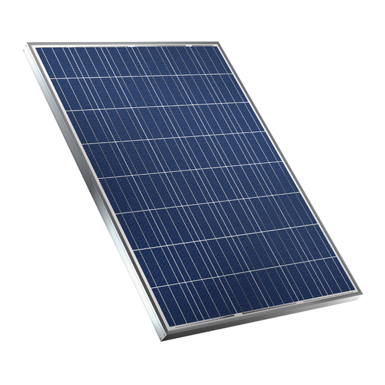
Viessmann VITOVOLT 200 Installation And Service Instructions Manual
Hide thumbs
Also See for VITOVOLT 200:
- Installation instructions manual (48 pages) ,
- Technical manual (20 pages) ,
- Operating instructions for the system user (4 pages)
Summary of Contents for Viessmann VITOVOLT 200
- Page 1 VIESMANN Installation and service instructions for contractors Vitovolt 200 Photovoltaic modules VITOVOLT 200 Please keep safe. 5609 706 GB 11/2016...
- Page 2 Safeguard the system against reconnection. charge static loads. ■ Repair work Please note Repairing components that fulfil a safety func- tion can compromise the safe operation of the system. Replace faulty components only with genuine Viessmann spare parts.
- Page 3 Installing non-authorised components and making non-approved modifications or con- versions can compromise safety and may inva- lidate our warranty. For replacements, use only original spare parts supplied or approved by Viessmann.
-
Page 4: Table Of Contents
Commissioning, inspec- Steps - commissioning, inspection and maintenance ......11 tion, maintenance Commissioning/service Commissioning report ................13 reports Commissioning, maintenance/service ........... 15 Disposal Final decommissioning and disposal ............. 17 Certificates Declaration of Conformity ..............18 Vitovolt 200 ..................18 ■... - Page 5 The manufacturer/supplier accepts no liability for any such damage. The user alone bears the risk. Observation of technical documentation, such as the "Vitovolt 200 installation information" and "Vitovolt 200 operating instructions" is also part of intended use.
- Page 6 Preparing for installation Requirements specified by the power supply utility When operating the photovoltaic unit as a grid feed system, observe all current requirements and regula- tions of your local power supply utility. The photovoltaic system must be suitable for operation with the power grid of your local power supply utility, and any interference affecting the grid or third parties must be reliably prevented.
-
Page 7: Information On The Mounting Frame
Installation sequence Information on the modules Inappropriate handling can damage the modules. Modules that are not installed: ■ ■ Never lift the modules by their sockets or connecting Store modules with the glass facing up and cover cables (at the back of the module). them. -
Page 8: Information On Earthing/Equipotential Bonding
Installation sequence Electrical connection (cont.) Parallel connection: To prevent overheating, select a cable cross-section ■ ■ The current can be increased by connecting the and connection capacity that is appropriate for the modules in parallel. To do this, the positive terminal maximum short circuit current of the system. - Page 9 Installation sequence Electrical connection (cont.) Plug-in connections: ■ – Open plug-in connections must be free from con- tamination (dust, foreign bodies) and dry. Never use plug-in connections with contaminated or damp contacts. Never insert any live parts into plugs or sockets. –...
-
Page 10: Connection Examples
Installation sequence Electrical connection (cont.) Connection examples Example 1 Example 2 System of 1 string with 8 modules; modules connected System of 2 strings with 7 modules per string; modules in series connected in series PV module Connecting cables DC isolator Inverter Public grid... -
Page 11: Steps - Commissioning, Inspection And Maintenance
Commissioning, inspection, maintenance Steps - commissioning, inspection and maintenance Commissioning steps Inspection steps Maintenance steps Page • 1. Shutting down the system....................12 • 2. Cleaning the PV modules....................12 • • 3. Checking the inverter......................12 • • • 4. - Page 12 Commissioning, inspection, maintenance Shutting down the system Please note Disconnect the DC voltage and mains voltage sides, To avoid appliance damage, always cover mod- e.g. at the DC isolation point and a mains isolator. ules before carrying out any work on the PV sys- Safeguard against unauthorised reconnection.
-
Page 13: Commissioning Report
Commissioning/service reports Commissioning report System user System location Name/company Name/company Street, house number Street, house number Postcode, town Postcode, town Telephone number Date Email Delivery note number Date System installed by System commissioned by Name/customer number Name/company Street, house number Street, house number Postcode, town Postcode, town... - Page 14 Commissioning/service reports Commissioning report (cont.) Collector angle of inclination α = ....° α α α Module orientation Deviation from south: ....° 90° 90° 0° Installation location Pitched roof Yes/No Flat roof Yes/No Freestanding, on supports Yes/No Shading Yes/No Photovoltaic modules Type/manufacturer Short circuit current (Isc) Open circuit voltage (Uoc)
-
Page 15: Commissioning, Maintenance/Service
Commissioning/service reports Commissioning report (cont.) Inverter Device 1 Device 2 Type/manufacturer/serial number Rated DC output Maximum DC output Rated AC output Further system information Generator earthed? Yes/No Positive/Negative Reverse current protection? Yes/No ....V/A DC isolator? Yes/No Type: Test report String Inverter device 1/2 Number of modules Short circuit current... - Page 16 Commissioning/service reports Commissioning, maintenance/service (cont.) Maintenance/service Maintenance/service Maintenance/service Date: Maintenance/service Maintenance/service Maintenance/service Date: Maintenance/service Maintenance/service Maintenance/service Date:...
-
Page 17: Final Decommissioning And Disposal
Disposal Final decommissioning and disposal Viessmann products can be recycled. Components and substances from the system are not part of ordi- nary household waste. Isolate the system from the power supply for decom- missioning. All components must be disposed of correctly. -
Page 18: Declaration Of Conformity
Certificates Declaration of Conformity Vitovolt 200 We, Viessmann Werke GmbH & Co. KG, 35107 Allendorf, Germany, declare as sole responsible body that the named product complies with the provisions of the following directives and regulations: 2014/35/EU Low Voltage Directive 2014/30/EU... - Page 20 Viessmann Werke GmbH & Co. KG Viessmann Limited D-35107 Allendorf Hortonwood 30, Telford Telephone: +49 6452 70-0 Shropshire, TF1 7YP, GB Fax: +49 6452 70-2780 Telephone: +44 1952 675000 www.viessmann.com Fax: +44 1952 675040 E-mail: info-uk@viessmann.com...


Need help?
Do you have a question about the VITOVOLT 200 and is the answer not in the manual?
Questions and answers