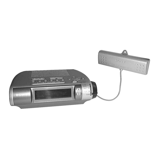
Sony ICF-C255RC Service Manual
Fm/mw/lw radio controlled clock radio
Hide thumbs
Also See for ICF-C255RC:
- Operating instructions (2 pages) ,
- Specifications (2 pages) ,
- Limited warranty (1 page)
Summary of Contents for Sony ICF-C255RC
- Page 1 ICF-C255RC SERVICE MANUAL AEP Model Ver 1.0 2000. 05 SPECIFICATIONS FM/MW/LW RADIO CONTROLLED CLOCK RADIO...
-
Page 2: Section 1 General
SECTION 1 This section is extracted from instruction manual. GENERAL SAFETY CHECK-OUT After correcting the original service problem, perform the following safety checks before releasing the set to the customer. Check the area of your repair for unsoldered or poorly-soldered Look for parts which, through functioning, show obvious signs connections. - Page 3 — 3 —...
-
Page 4: Section 2 Disassembly
SECTION 2 DISASSEMBLY • The equipment can be removed using the following procedure. Ferrite rod antenna board Cabinet (upper) Key board Main board Power board Note : Follow the disassembly procedure in the numerical order given. 2-1. CABINET (UPPER) × 14) 1 Five screws (M3 4 Cabinet (upper) 8 Box assy, ANT... -
Page 5: Main Board
2-2. KEY BOARD 4 Key board 1 Two claws 2 Two claws 6 Chassis 5 Two claws 3 Connector (CN200) 7 Cabinet (lower) 2-3. MAIN BOARD 5 Connector (CN2) × 8) 2 Two screws (BTP 2 3 Alarm dial board 6 LED board 1 Connector (CN201) 7 Connector (CN150) -
Page 6: Power Board
2-4. POWER BOARD 4 Power cord 6 Transformer power 2 Terminal 7 Power board 3 Remove the two solderings. 5 Remove the six solderings. 2-5. FERRITE ROD ANTENNA BOARD Antenna cord setting (BOX ASSY, ANT) 4 Box (upper), antenna Set the Antenna cord as illustrated below, then install the antenna box (upper). - Page 7 SECTION 3 ELECTRICAL ADJUSTMENTS 2-6. POWER CORD AND ANTENNA CORD SETTING [FM] • Adjusting Location: MAIN board (Component Side) Setting: L4-1 MW TRACKING adjustment BAND switch: FM T1 AM IF adjustment FM RF signal generator level meter FM TRACKING adjustment 0.01 µF L1 MW FREQUENCY COVERAGE adjustment...
- Page 8 ICF-C255RC SECTION 4 DIAGRAMS 4-1. PRINTED WIRING BOARDS KEY BOARD MAIN BOARD TUNING S202 (SPEAKER) CN200 S200 S201 S210 S204 • Semiconductor Location Ref. No. Location S203 CN202 S213 BAND CLOCK S212 A-RESET W151 S209 S208 S207 S206 S205 S214...
- Page 9 ICF-C255RC 4-2. SCHEMATIC DIAGRAM Note on Schematic Diagram: • All capacitors are in µF unless otherwise noted. pF: µµF 50 WV or less are not indicated except for electrolytics and tantalums. • All resistors are in Ω and W or less unless otherwise specified.
-
Page 12: Section 6 Electrical Parts List
FERRITE-ROD ANTENNA SECTION 6 ELECTRICAL PARTS LIST MAIN NOTE: • Due to standardization, replacements in the • CAPACITORS: • SEMICONDUCTORS parts list may be different from the parts uF: µF In each case, u: µ, for example: specified in the diagrams or the components •... - Page 13 MAIN Ref. No. Part No. Description Remarks Ref. No. Part No. Description Remarks 1-163-132-00 CERAMIC CHIP 430PF 5.00% 50V < TRIMMER > 1-126-960-11 ELECT 20.00% 50V 1-126-934-11 ELECT 220uF 20.00% 10V 1-141-601-21 CAP, ADJ 1-163-263-11 CERAMIC CHIP 330PF 5.00% 50V 1-141-605-11 CAP, ADJ 1-163-021-91 CERAMIC CHIP 0.01uF...
- Page 14 MAIN Ref. No. Part No. Description Remarks Ref. No. Part No. Description Remarks JC117 1-216-296-91 SHORT Q100 8-729-216-22 TRANSISTOR 2SA812-T1-M5M6 JC119 1-216-296-91 SHORT Q101 1-801-806-11 TRANSISTOR DTC144EKA-T146 JC120 1-216-296-91 SHORT Q151 8-729-840-00 TRANSISTOR 2SD400E-MP-AE JC121 1-216-296-91 SHORT JC122 1-216-296-91 SHORT <...
- Page 15 ICF-C255RC MAIN POWER Ref. No. Part No. Description Remarks Ref. No. Part No. Description Remarks < TRANSFORMER > MISCELLANEOUS ************** 1-404-790-11 TRANSFORMER, IF 1-553-856-00 SWITCH, KEYBOARD < VARIABLE RESISTOR > * 20 1-535-771-11 TERMINAL 1-674-952-11 FERRITE-ROD ANTENNA BOARD 1-228-790-00 RES, VAR, CARBON 50K (VOL) 1-504-748-21 SPEAKER (6.6cm)


Need help?
Do you have a question about the ICF-C255RC and is the answer not in the manual?
Questions and answers