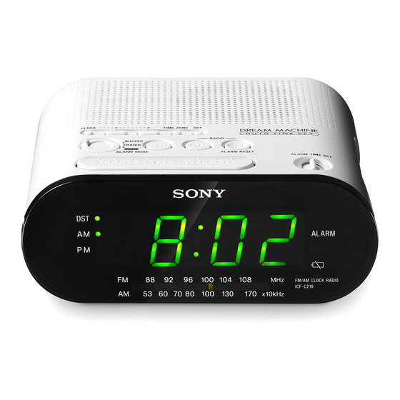
Sony ICF-C218 Service Manual
Fm/am clock radio
Hide thumbs
Also See for ICF-C218:
- User manual ,
- Operating instructions (2 pages) ,
- Specifications (2 pages)
Table of Contents
Advertisement
SERVICE MANUAL
Ver. 1.1 2007.04
Sony Corporation
9-887-637-02
Personal Audio Division
2007D02-1
Published by Sony Techno Create Corporation
© 2007.04
SPECIFICATIONS
Time display:
Model for Australian, Central & South American
and Mexico: 12-hour system
Model for other countries/ regions: 24-hour system
Frequency range:
Band
Frequency
FM
87.5 – 108 MHz
AM
530 – 1 710 kHz
Speaker:
inches) dia., 8 Ω
Approx. 6.6 cm (2
5
/
8
Power output:
150 mW (at 10% harmonic distortion)
Power requirements:
Model for Central & South American and Mexico: 120 V
AC, 60 Hz
Model for Australian: 230 V AC, 50 Hz
Model for Thailand: 230 V AC, 50 Hz
Model for other countries/ regions: 230 – 240 V
AC, 50 Hz
For power backup: 3 V DC, one CR2032 battery
Dimensions:
Approx. 155 × 64.5 × 150 mm (w/h/d)
× 2
× 6 inches) incl. projecting parts and controls
1
5
(6
/
/
8
8
Mass:
Model for Central & South American and Mexico: approx.
462.2g (1 lb 0.3 oz) incl. CR2032 battery
Model for Australian: approx.
498.2g (1 lb 2.1 oz) incl. CR2032 battery
Model for other countries/regions: approx.
470.2g (1 lb 0.6 oz) incl. CR2032 battery
Design and specifications are subject to change without notice.
ICF-C218
Australian Model
FM/AM CLOCK RADIO
E Model
Advertisement
Table of Contents

Related Manuals for Sony ICF-C218


Summary of Contents for Sony ICF-C218
- Page 1 Model for other countries/regions: approx. 470.2g (1 lb 0.6 oz) incl. CR2032 battery Design and specifications are subject to change without notice. FM/AM CLOCK RADIO Sony Corporation 9-887-637-02 Personal Audio Division 2007D02-1 Published by Sony Techno Create Corporation © 2007.04...
-
Page 2: Table Of Contents
LIST ARE CRITICAL TO SAFE OPERATION. REPLACE THESE It is best to use only unleaded solder but unleaded solder may COMPONENTS WITH SONY PARTS WHOSE PART NUMBERS also be added to ordinary solder. APPEAR AS SHOWN IN THIS MANUAL OR IN SUPPLEMENTS PUBLISHED BY SONY. -
Page 3: General
ICF-C218 SECTION 1 GENERAL This section is extracted from instruction manual. LOCATING THE CONTROLS FM wire antenna (Except CLOCK Central America and Mexico model) RADIO BUZZER RADIO SLEEP ALARM MODE ALARM RESET ALARM TIME SET AC power cord SNOOZE DATE... -
Page 4: Setting The Alarm
ICF-C218 To stop the Alarm Setting the clock Rotate the unit horizontally for optimum reception. Press RADIO OFF/ALARM RESET to A ferrite bar AM antenna is built-in to the unit. turn off the alarm. and date The alarm will come on again at the same time the Set the clock and date according to the following next day. -
Page 5: Disassembly
ICF-C218 SECTION 2 DISASSEMBLY 2-1. DISASSEMBLY FLOW 2-2. FRONT PANEL, UPPER CABINET ASSY (Page 5) 2-3. MAIN BOARD (Page 6) 2-2. FRONT PANEL, UPPER CABINET ASSY 8 upper cabinet assy 2 five claws lower cabinet assy 6 three screws (+BVTP2.6) -
Page 6: Main Board
ICF-C218 2-3. MAIN BOARD 1 screw (+BVTP2.6) 5 MAIN board 2 two claws 3 two claws cabinet (lower) POWER CORD AND POINTER INSTALLATION power cord wind the power cord clockwise once. 2 turn the knob (VOL) fully counterclockwise. lower cabinet (top view) 1 turn the knob (TUNE) fully counterclockwise. -
Page 7: Electrical Adjustments
ICF-C218 SECTION 3 ELECTRICAL ADJUSTMENTS • Repeat the procedures in each adjustment several times, and TUNER SECTION the frequency coverage and tracking adjustments should be finally done by the trimmer capacitors. 0dB=1µV AM Section Procedure : AM IF ADJUSTMENT BAND : AM Adjust for a maximum reading on level meter. - Page 8 ICF-C218 Adjustment Location: MAIN board (Component side) L3 : FM Frequency Coverage Adjustment T1 : AM IF Adjustment TP1 (RF IN) (Conductor side) L1 : AM Tracking Adjustment CT1-1-4 AM Frequency Coverage Adjustment CT1-1-4 CT1-3 : FM Frequency Coverage Adjustment...
-
Page 9: Diagrams
ICF-C218 SECTION 4 Ver. 1.1 DIAGRAMS :Uses unleaded solder. 4-1. PRINTED WIRING BOARD ANT1 FM WIRE MAIN BOARD ANTENNA SP, TH, AUS T301 POWER TRANSFORMER AC IN C307 C&SA, MX FERRITE-BAR ANTENNA BAND W102 CLOCK TP1 (RF IN) R217 R218... -
Page 10: Schematic Diagram
ICF-C218 Ver. 1.1 4-2. SCHEMATIC DIAGRAM • See page 11 for IC Block Diagrams. • See page 11 for Waveforms. LED101 L3, CT1-3 L4, CT1-4 LED DISPLAY MAIN BOARD CV1-1-CV1-4 FREQUENCY FREQUENCY TUNING COVERAGE COVERAGE AM OSC 1 2 3 4 5 6 7 8 9 10 11 12 13 14 15 16 17 18... - Page 11 ICF-218 • IC Block Diagram IC1 CXA1019S AM IF DET AGC TUNING METER AF POWER AMP AM FE FM IF DISCRIMINATOR FM FE • Waveforms – MAIN Board – IC101 qs (XT1) 756 mV 31.3 µS 0.2V/DIV, 10 µsec/DIV...
-
Page 12: Exploded Views
ICF-C218 Ver. 1.1 SECTION 5 EXPLODED VIEWS NOTE: The components identified by mark 0 or • The mechanical parts with no reference number • -XX, -X mean standardized parts, so they may dotted line with mark 0 are critical for in the exploded views are not supplied. -
Page 13: Electrical Parts List
ICF-C218 Ver. 1.1 SECTION 6 MAIN ELECTRICAL PARTS LIST NOTE: • Due to standardization, replacements in the • COILS The components identified by mark 0 uH: µH parts list may be different from the parts or dotted line with mark 0 are critical specified in the diagrams or the components •... - Page 14 ICF-C218 Ver. 1.1 MAIN Ref. No. Part No. Description Remarks Ref. No. Part No. Description Remarks L202 1-410-513-11 INDUCTOR 22uH 1-798-042-11 SWITCH, SLIDE (ALARM MODE) 1-798-044-11 SWITCH, TACTILE (RADIO ON) < LED > 1-798-044-11 SWITCH, TACTILE (SET +) 1-798-044-11 SWITCH, TACTILE (SET –) LED101 1-802-373-11 ELEMENT, LED INDICATOR (SP, TH) LED101 1-802-374-11 ELEMENT, LED INDICATOR (C&SA, MX, AUS)
- Page 15 ICF-C218 MEMO...
- Page 16 ICF-C218 REVISION HISTORY Clicking the version allows you to jump to the revised page. Also, clicking the version at the upper right on the revised page allows you to jump to the next revised page. Ver. Date Description of Revision 2007.03...
Need help?
Do you have a question about the ICF-C218 and is the answer not in the manual?
Questions and answers
print manual for opperating