
Related Manuals for MATRIX TECHNOLOGY MPS-H-3 Series

Summary of Contents for MATRIX TECHNOLOGY MPS-H-3 Series
- Page 1 MPS-H-3 SERIES DC POWER SUPPLY USER MANUAL Certification: NOM-001-SCFI-2018 (NMX-I-60950-1-NYCE-2015) MATRIX TECHNOLOGY INC.
- Page 2 Preface Respected users: Hello! Thank you for purchasing a brand-new MATRIX instrument. In order to use this instrument correctly, please read the full text of this manual carefully before using this instrument, especially the "safety precautions" part. If you have read the full text of this manual, it is recommended that you keep this manual properly and place it with the instrument or put it in a place where you can read it at any time for future use.
- Page 3 Products are protected by patents in China or other countries, including patents that have been obtained or are applying for ● MATRIX TECHNOLOGY INC. reserves the right to change product specifications and prices. ● is a registered trademark of MATRIX TECHNOLOGY INC.
- Page 4 Calibration and calibration statement The company specifically declares that the equipment listed in this manual fully complies with the specifications and characteristics stated in the company's technical specifications. This instrument has been verified by our company before leaving the factory. The verification procedures and steps are in compliance with the specifications and standards of the Electronic Inspection Center.
- Page 5 Content CHAPTER Ι PRODUCT INTRODUCTION......................... 1 CHAPTER Ⅱ TECHNICAL SPECIFICATION........................2 2.1 MAIN TECHNICAL SPECIFICATION..........................2 2.2 SUPPLEMENTARY CHARACTORISTICS........................2 CHAPTER Ⅲ QUICK START..............................3 3.1 FRONT PANNEL AND REAR PANNEL INTRODUCTION...................3 3.2 PRE INSPECTION................................5 3.3 IF THE POWER SUPPLY CANNOT BE POWERED ON....................5 CHAPTER Ⅳ...
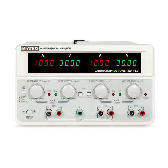
- Page 6 Chapter 1 Product Introduction MPS-H-3 series DC power supply is a new generation of high-quality linear DC power supply, both channels can independently adjust the voltage and current, one fixed 5V/3A output, stable voltage and current automatic conversion, high stability, high reliability, and high precision . Two channels can display output voltage and current simultaneously, which has a very high cost-effective advantage.
- Page 7 2.2 Additional features Recommended calibration frequency: 1 year/1 time Cooling method: forced air cooling Operating environment temperature: 0 to 40 ℃ Storage temperature: -15 to 80 ℃ Use environment: indoor use design, pollution level 2, maximum humidity 80%RH. Chapter 3 Quick Start This chapter will briefly introduce the appearance and basic functions of the MPS-3003H-3 series DC power supply, so that you can quickly know about the MPS-3003H-3 series DC power supply.
- Page 8 ⑰Instrument power switch ⑱CH1 current adjustment knob ⑲One-key series/parallel/function button ⑳Series and parallel indicator lights ○ 2 1CH1 constant current indicator ○ 2 2CH1 constant pressure indicator The rear panel of MPS-H-3 series DC power supply is shown in the figure below.
- Page 9 Figure 3.2 Rear panel of MPS-H-3 series DC power supply ① Instrument power input socket ② Instrument power input switch ③ Heat dissipation hole 3.2 Pre-check Please follow the steps below to check the power supply to ensure that the power supply can be used normally.
- Page 10 3.3 If the power fails to start Use the following methods to solve the problems you may encounter when turning on the power. 1. Check if the power cord is connected Fuse specification Model 230V 115V 3003H-3 3005H-3 3010H-3 6003H-3 6005H-3 2.
- Page 11 4.1 Voltage/current setting When the power supply is in standby or output mode, lightly press the voltage/current knob, the corresponding setting position on the screen will flash. At this time, you can turn the knob left and right to change the setting value. When the setting value is flashing, press the knob again to change the setting position.
- Page 12 Parallel mode Independent mode Remarks: 1. Lightly press the "one-key series/parallel/function menu button" on the left once the power supply will enter the series working state, and the current window will prompt "SE" series and parallel indicator lights to show green, as shown in the figure "series mode", the output should Connect the negative terminal of CH1 and the positive terminal of CH2, and the main circuit "OUTPUT2"...
- Page 13 2. Output state setting when power on: SE2 P-UP ON/OFF (ON means power-on to keep output status, OFF means power-on to keep off status, use CH1 current knob to switch menu steps, CH2 voltage knob to switch ON/OFF status, Tap the "one-key series/parallel/function menu button" to exit the menu.) 3.
- Page 14 4. CH1 voltage and current lower limit setting: SE4 CH1L 0.000 0.000 (CH2 current display window is the current lower limit, CH2 voltage display window is the voltage lower limit, use the CH1 current knob to switch menu steps, lightly press the CH2 current knob current window value Flashing, you can turn the knob left and right to change the lower limit of current at this time, press the knob to change the setting position, press the CH2 voltage knob, and the voltage window value flashes, at this time, you can rotate the knob to change the lower limit of voltage, and press the knob to change Set the position, tap the "one-key series/parallel/function menu button"...
- Page 15 voltage, and press the knob to change Set the position, tap the "one-key series/parallel/function menu button" to exit the menu.) 7. CH2 voltage and current upper limit setting: SE7 CH2L 5.100 31.00 (CH2 current display window is the current upper limit value, CH2 voltage display window is the voltage upper limit value, use the CH1 current knob to switch menu steps, lightly press the CH2 current knob current window value Flashing, you can turn the knob left and right to change the upper limit of current at this time, lightly press the knob to change the setting position, lightly press the CH2 voltage knob, the voltage window value flashes, at this time you can rotate the knob left or right to change...
- Page 16 figure below), if you want to change the OCP setting value, you can lightly press the current window number corresponding to the CH1/CH2 current adjustment knob Flashing, turn the knob left and right to change the setting value. When in the setting state, lightly press the knob to change the setting position (CH1 current adjustment knob sets CH1 OCP, CH2 current adjustment knob sets CH2 OCP).
- Page 17 CH1 OCP protection hint CH2 OCP protection hint 4.OVP protection: When the output voltage exceeds the OVP setting value, the voltage window of this channel will prompt "OVP" and turn off the output (as shown in the figure below). The CH1 and CH2 channels have independent OVP settings and protection functions.
- Page 18 refer to the specific warning or caution information in this manual to avoid personal injury or damage to the instrument. Safety sign WARNING He reminds the user of certain operations, practices or conditions that may cause personal injury. ATTENTION He reminds the user of operational procedures, practices, conditions, etc. that may result in damage to the instrument or permanent loss of data 〨...
Need help?
Do you have a question about the MPS-H-3 Series and is the answer not in the manual?
Questions and answers