Table of Contents
Advertisement
Quick Links
www.ti.com
User's Guide
LM10500 Step-Down Converter Evaluation Module User's
Guide
Overview..................................................................................................................................................................1
2 Adaptive Voltage Scaling Technology..................................................................................................................................
3
Features...................................................................................................................................................................................2
4 Applications............................................................................................................................................................................
Overview.........................................................................................................................................................2
Circuit.....................................................................................................................................................4
Guide...................................................................................................................................................................5
7.1 Default Setting and Operation Options..............................................................................................................................
Descriptions.........................................................................................................................................................5
7.3 Jumper Settings.................................................................................................................................................................
Guide......................................................................................................................................................................6
8.1 Standalone Operation........................................................................................................................................................
8.2 PWI Communication Using USB2PWI Board....................................................................................................................
8.3 PWI Communication Using 9-Pin Connector J1................................................................................................................
Guide...............................................................................................................................................................7
9.2 GUI Layout and Conventions.............................................................................................................................................
10 Typical Performance Characteristics................................................................................................................................
11 Evaluation Board Schematic.............................................................................................................................................
Layout....................................................................................................................................................15
14 Revision History.................................................................................................................................................................
Trademarks
PowerWise
®
is a registered trademark of Phybridge Inc..
All trademarks are the property of their respective owners.
1 LM10500 Overview
The LM10500 is a 5-A energy management unit (EMU) that actively reduces system level power consumption
by utilizing a continuous, real-time, closed-loop adaptive voltage scaling (AVS) scheme. The LM10500 operates
cooperatively with PowerWise
adaptively over process and temperature variations. The device is controlled through PWI 1.0 or PWI 2.0
high-speed serial interface.
A typical power saving of 40% can be achieved when LM10500 is used with AVS-compatible ASICs, SoCs, and
processors.
2 Adaptive Voltage Scaling Technology
PowerWise adaptive voltage scaling (AVS) technology is an advanced closed-loop technology for reducing
active and standby energy consumption of digital processing engines and ASICs. Hardware performance
monitor (HPM) is designed into the digital engine together with an advanced power controller (APC) to monitor
the performance of the silicon based on process and temperature variation. Information is fed back to an energy
management unit (EMU), which then sets the voltage precisely according to the needs of the processor. The
AVS technology enables optimum power delivery to the processors, ASICs, and SoCs, which maximizes overall
system energy savings. AVS technology is process and architecture independent.
SNVA453B - AUGUST 2011 - REVISED JANUARY 2022
Submit Document Feedback
Table of Contents
Board...........................................................................................................................7
Write......................................................................................................................................9
Materials.....................................................................................................................................14
®
AVS-compatible ASICs, SoCs, and processors to optimize supply voltages
Copyright © 2022 Texas Instruments Incorporated
LM10500 Step-Down Converter Evaluation Module User's Guide
Table of Contents
1
2
5
6
6
6
7
8
11
13
17
1
Advertisement
Table of Contents

Related Manuals for Texas Instruments LM10500


Summary of Contents for Texas Instruments LM10500
-
Page 1: Table Of Contents
The device is controlled through PWI 1.0 or PWI 2.0 high-speed serial interface. A typical power saving of 40% can be achieved when LM10500 is used with AVS-compatible ASICs, SoCs, and processors. 2 Adaptive Voltage Scaling Technology PowerWise adaptive voltage scaling (AVS) technology is an advanced closed-loop technology for reducing active and standby energy consumption of digital processing engines and ASICs. -
Page 2: Features
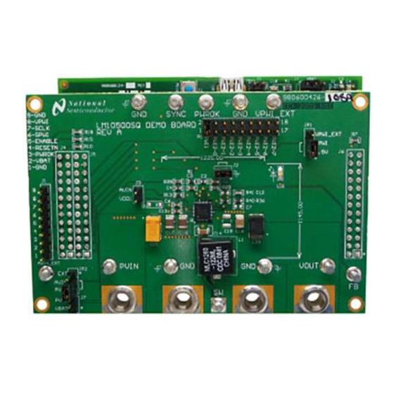
The LM10500 evaluation boards can operate standalone, communicate to a USB2PWI interface board, or to an external AVS primary. The USB2PWI interface board and a graphic user interface (GUI) are included in the evaluation kit to easily evaluate the LM10500 AVS functionality from a PC. The evaluation kit is consist of: •... - Page 3 Evaluation Kit Overview Figure 5-1. LM10500 Evaluation Board Figure 5-2. USB2PWI Interface Board SNVA453B – AUGUST 2011 – REVISED JANUARY 2022 LM10500 Step-Down Converter Evaluation Module User's Guide Submit Document Feedback Copyright © 2022 Texas Instruments Incorporated...
-
Page 4: Typical Application Circuit
Domain 5A max COMP AGND PWROK PWROK ASIC / SoC DGND Figure 6-1. Typical Application Circuit LM10500 Step-Down Converter Evaluation Module User's Guide SNVA453B – AUGUST 2011 – REVISED JANUARY 2022 Submit Document Feedback Copyright © 2022 Texas Instruments Incorporated... -
Page 5: Connection Guide
VOUT terminal is connected to the output capacitor on the board and should be connected to the load FB terminal is connected to the FB pin of the LM10500. It can be used to monitor the AVS voltage command programmed by PWI. Careful not to add any noise to the FB terminal or load it by any means. -
Page 6: Jumper Settings
To simplify the evaluation of the AVS functions in the LM10500, the evaluation board is designed to operate with the USB2PWI interface board (included in the evaluation kit). With the USB2PWI board, PWI registers and LM10500 operating states can be controlled by a PC through a simple register-based graphical user interface (GUI). -
Page 7: Pwi Communication Using 9-Pin Connector J1
PWI communication. This connector allows the LM10500 to be tested in a closed AVS loop with a primary controller, such as AVS compatible ASICs, SoCs, and processors. -
Page 8: Gui Layout And Conventions
Reading from unused bits returns '0' and writing to unused bits are ignored. The top four lines of the GUI are the PWI registers of the LM10500. R0 controls the core voltage, ranging from 00h to 7Fh. R4 shows the PWI version: 01h means PWI1.0 and 02h means PWI2.0. R9 is the core voltage offset and the default value differs in LM10500SQ-0.8 and LM10500SQ-1.0. -
Page 9: Register Read And Register Write
Register Read • Click button ‘R’ at the right end of a register to read in the value of this register from the LM10500. • Click menu Operations, then select Read all (Ctrl + R), to read in all the register values. - Page 10 Click menu Operations, then select Direct access, to write to a register by providing its address and value, as shown in Figure 9-5. LM10500 Step-Down Converter Evaluation Module User's Guide SNVA453B – AUGUST 2011 – REVISED JANUARY 2022 Submit Document Feedback Copyright © 2022 Texas Instruments Incorporated...
-
Page 11: Typical Performance Characteristics
INPUT VOLTAGE, PVIN (V) LOAD CURRENT (A) Figure 10-5. Line Regulation (%) Figure 10-6. Load Regulation (%) SNVA453B – AUGUST 2011 – REVISED JANUARY 2022 LM10500 Step-Down Converter Evaluation Module User's Guide Submit Document Feedback Copyright © 2022 Texas Instruments Incorporated... - Page 12 Figure 10-11. Soft Start With 0.5V Pre-bias Voltage, Figure 10-12. Switching Waveform With 5 A Load CCM Operation, Triggered By PWI 'Wakeup' Command LM10500 Step-Down Converter Evaluation Module User's Guide SNVA453B – AUGUST 2011 – REVISED JANUARY 2022 Submit Document Feedback Copyright © 2022 Texas Instruments Incorporated...
-
Page 13: Evaluation Board Schematic
Evaluation Board Schematic 11 Evaluation Board Schematic Figure 11-1. LM10500 Evaluation Board Schematic (Part I) Figure 11-2. LM10500 Evaluation Board Schematic (Part II) SNVA453B – AUGUST 2011 – REVISED JANUARY 2022 LM10500 Step-Down Converter Evaluation Module User's Guide Submit Document Feedback... -
Page 14: Evaluation Board Bill Of Materials
VISHAY/DALE 2KΩ 0603 1% ** RC0603FR-072KL YAGEO NL * 10 KΩ 0603 1% ** RC0603FR-710KL YAGEO LM10500 Step-Down Converter Evaluation Module User's Guide SNVA453B – AUGUST 2011 – REVISED JANUARY 2022 Submit Document Feedback Copyright © 2022 Texas Instruments Incorporated... -
Page 15: Evaluation Board Layout
13 Evaluation Board Layout Figure 13-1. Top Layer Figure 13-2. Middle Layer 1 Figure 13-3. Middle Layer 2 SNVA453B – AUGUST 2011 – REVISED JANUARY 2022 LM10500 Step-Down Converter Evaluation Module User's Guide Submit Document Feedback Copyright © 2022 Texas Instruments Incorporated... - Page 16 Evaluation Board Layout www.ti.com Figure 13-4. Bottom Layer Figure 13-5. Top Overlay Figure 13-6. Bottom Overlay LM10500 Step-Down Converter Evaluation Module User's Guide SNVA453B – AUGUST 2011 – REVISED JANUARY 2022 Submit Document Feedback Copyright © 2022 Texas Instruments Incorporated...
-
Page 17: Revision History
Updated the numbering format for tables, figures, and cross-references throughout the document....1 • Updated user's guide title........................... • Edited user's guide for clarity..........................1 SNVA453B – AUGUST 2011 – REVISED JANUARY 2022 LM10500 Step-Down Converter Evaluation Module User's Guide Submit Document Feedback Copyright © 2022 Texas Instruments Incorporated... - Page 18 STANDARD TERMS FOR EVALUATION MODULES Delivery: TI delivers TI evaluation boards, kits, or modules, including any accompanying demonstration software, components, and/or documentation which may be provided together or separately (collectively, an “EVM” or “EVMs”) to the User (“User”) in accordance with the terms set forth herein.
- Page 19 www.ti.com Regulatory Notices: 3.1 United States 3.1.1 Notice applicable to EVMs not FCC-Approved: FCC NOTICE: This kit is designed to allow product developers to evaluate electronic components, circuitry, or software associated with the kit to determine whether to incorporate such items in a finished product and software developers to write software applications for use with the end product.
- Page 20 www.ti.com Concernant les EVMs avec antennes détachables Conformément à la réglementation d'Industrie Canada, le présent émetteur radio peut fonctionner avec une antenne d'un type et d'un gain maximal (ou inférieur) approuvé pour l'émetteur par Industrie Canada. Dans le but de réduire les risques de brouillage radioélectrique à...
- Page 21 www.ti.com EVM Use Restrictions and Warnings: 4.1 EVMS ARE NOT FOR USE IN FUNCTIONAL SAFETY AND/OR SAFETY CRITICAL EVALUATIONS, INCLUDING BUT NOT LIMITED TO EVALUATIONS OF LIFE SUPPORT APPLICATIONS. 4.2 User must read and apply the user guide and other available documentation provided by TI regarding the EVM prior to handling or using the EVM, including without limitation any warning or restriction notices.
- Page 22 Notwithstanding the foregoing, any judgment may be enforced in any United States or foreign court, and TI may seek injunctive relief in any United States or foreign court. Mailing Address: Texas Instruments, Post Office Box 655303, Dallas, Texas 75265 Copyright © 2019, Texas Instruments Incorporated...
- Page 23 TI products. TI’s provision of these resources does not expand or otherwise alter TI’s applicable warranties or warranty disclaimers for TI products. TI objects to and rejects any additional or different terms you may have proposed. IMPORTANT NOTICE Mailing Address: Texas Instruments, Post Office Box 655303, Dallas, Texas 75265 Copyright © 2022, Texas Instruments Incorporated...
Need help?
Do you have a question about the LM10500 and is the answer not in the manual?
Questions and answers