Advertisement
Cabled UV Biofouling Control - Quick Start Guide
This document is a summary guide for setting up Cabled UV Biofouling Control. Complete details may be found in
the Cabled UV Biofouling Control user manual.
Caution: Cabled UV emits Ultraviolet light. Care should be taken to avoid direct exposure to skin or eyes.
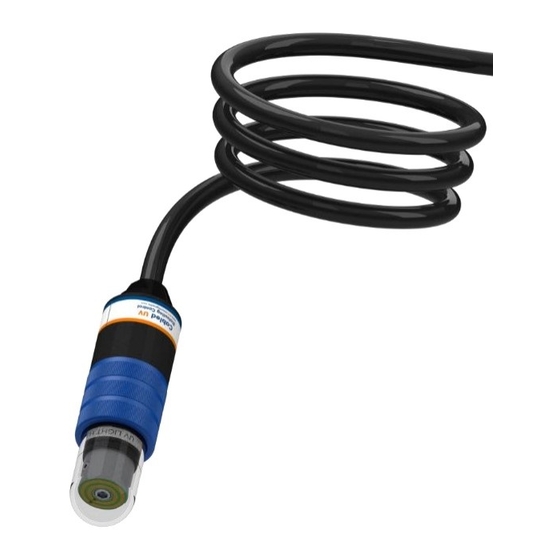
1. Mount device: Mount the head of the device within approximately 10 cm (~4 inches) of the target surface.
Be sure to clamp only the clamping surface of the device. Refer to Figure 2 for UV beam spread in seawater.
Device clamping surface
Target surface
Figure 1 – Cabled UV placed in proximity to the target surface
2. Align UV module to target surface: Unthread the blue retaining collar and pull uniformly on the quartz
tube to access and align the UV module. Loosen the setscrew to rotate and align the module. Reinstall in
the reverse order.
Slide
Retaining collar
Quartz tube
Figure 3 – Accessing the UV LED module
UV module
(horizontal shown)
Figure 2 - Approximate beam spread in seawater
7/64" hex head setscrew
Figure 4 - Location of setscrew allowing
rotation and alignment of the module.
Advertisement
Table of Contents

Related Manuals for AML Oceanographic PDC-DCC-05


Summary of Contents for AML Oceanographic PDC-DCC-05
- Page 1 Cabled UV Biofouling Control - Quick Start Guide This document is a summary guide for setting up Cabled UV Biofouling Control. Complete details may be found in the Cabled UV Biofouling Control user manual. Caution: Cabled UV emits Ultraviolet light. Care should be taken to avoid direct exposure to skin or eyes. 1.
- Page 2 3. Set duty cycle: If you are using AML’s Duty Cycle Controller (PDC-DCC-05), plug Cabled UV into the DCC’s female connector after setting the duty cycle. Duty cycle is controlled by 60 DIP switches located on the timing board enclosed in the DCC. Each switch represents two minutes, where up is on and down is off.
Need help?
Do you have a question about the PDC-DCC-05 and is the answer not in the manual?
Questions and answers