
Related Manuals for Art's-Way Manufacturing 6812D


Summary of Contents for Art's-Way Manufacturing 6812D
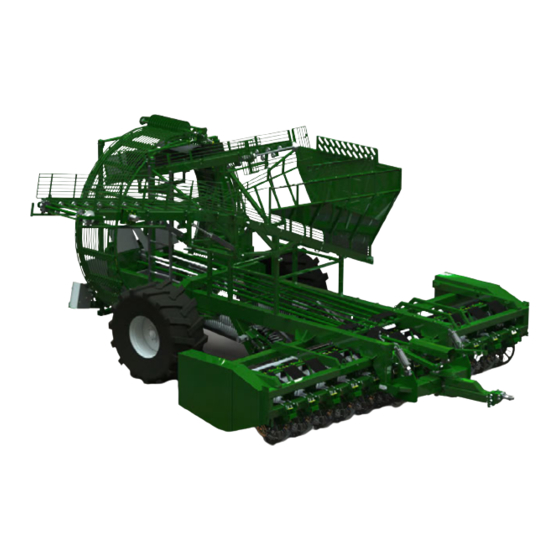
- Page 1 Art’s-Way Manufacturing Co., Inc. Model 6812D Sugar Beet Harvester Operator’s Manual 599500 Issued August 2014...
- Page 2 This symbol means ATTENTION! BECOME ALERT! YOUR SAFETY IS IN- VOLVED. The message that follows the symbol contains important information about your safety. Carefully read the message. Make sure you fully understand the causes of possible injury or death. IF THIS MACHINE IS USED BY AN EMPLOYEE, IS LOANED, OR IS RENTED, MAKE SURE THAT THE OPERATOR UNDERSTANDS THE TWO INSTRUCTIONS BELOW.
-
Page 3: To The Owner
6812D Sugar Beet Harvester is for reference only. This manual does not replace nor is it to be used for any machinery that may be attached to or used in conjunction with the 6812D Sugar Beet Harvester. -
Page 4: Parts & Service
PARTS & SERVICE PARTS & SERVICE As the purchaser of your new harvester, it is very important to consider the following factors: A. Original Quality B. Availability of Service Parts C. Availability of Adequate Service Facilities Art’s-Way Manufacturing Co., Inc. has an excellent dealership network ready to answer any questions you may have about your harvester. -
Page 5: Table Of Contents
TABLE OF CONTENTS TABLE OF CONTENTS TO THE OWNER SPECIFICATIONS AND DESIGN ARE SUBJECT TO CHANGE WITHOUT NOTICE Art’s-Way Manufacturing Co., Inc. STATEMENT OF PRODUCT LIABILITY IMPORTANT WARRANTY INFORMATION LIMITATIONS OF THIS MANUAL PARTS & SERVICE TABLE OF CONTENTS LIMITED WARRANTY SAFETY FIRST NOTICES OF DANGER, WARNING, AND CAUTION Safety Instructions... - Page 6 TABLE OF CONTENTS Manual No. 599500 ART’S-WAY MANUFACTURING COMPANY, INC.
-
Page 7: Table Of Contents
TABLE OF CONTENTS TABLE OF CONTENTS NAME PAGE SAFETY DECALS HARVESTER OVERVIEW TRACTOR/HARVESTER CONNECTION FIELD OPERATIONS HARVESTER ADJUSTMENTS TROUBLESHOOTING GUIDE LUBRICATION SCHEDULE SEASONAL STORAGE TRANSPORTING THE HARVESTER DEALER ASSEMBLY INSTRUCTIONS SPECIFICATIONS ART’S-WAY MANUFACTURING COMPANY, INC. Manual No. 599500... -
Page 8: Limited Warranty
LIMITED WARRANTY LIMITED WARRANTY Art’s-Way Manufacturing Co., Inc. warrants the products it sells to be free from defects in material and workmanship for a period of one (1) season after the date of delivery to the first (original) purchaser, subject to the following conditions: Art’s-Way Manufacturing Co., Inc. -
Page 9: Safety First
Art’s-Way Manufacturing Co., Inc. strives to make our equipment as safe as possible. The Art’s-Way Note: Contains additional information important 6812D Sugar Beet Harvester conforms to applicable to a procedure and will be found within the safety standards at the time of manufacturing. A regular text body of this manual. -
Page 10: Safety Instructions
SAFETY INSTRUCTIONS SAFETY INSTRUCTIONS GENERAL Safety Alert Symbols This is the safety alert symbol. It Most work related accidents are caused is used to alert you to potential by failure to observe basic safety rules personal injury hazards. Obey all or precautions. -
Page 11: Before Operating
SAFETY INSTRUCTIONS BEFORE OPERATING Keep all shields and guards in place and in good working condition. SAFETY INSTRUCTIONS Keep all bystanders, especially children, away from harvester while Do not wear loose fitting clothing as it may operation. catch in moving parts. Do not allow riders while the harvester is in Make sure all guards and shields are operation. -
Page 12: Hydraulic Safety
SAFETY INSTRUCTIONS HYDRAULIC SAFETY Make sure the Slow Moving Vehicle (SMV) emblem and all lights and reflectors required by local highway and transportation SAFETY authorities are properly in place, clean, and INSTRUCTIONS clearly visible to traffic. Follow all operating, maintenance, and safety instructions found in this Manu- Do not allow riders on any machinery during transport. -
Page 13: Tire Safety
SAFETY INSTRUCTIONS TIRE SAFETY ASSEMBLY SAFETY SAFETY SAFETY INSTRUCTIONS INSTRUCTIONS Follow all operating and safety instruc- Follow all assembly, operating, and tions found in this manual when work- safety instructions found in this manu- ing around tires. al when assembly this equipment. Have only a qualified tire dealer or tire Use adequate manpower to perform repair service perform tire repairs. - Page 14 SAFETY INSTRUCTIONS THIS PAGE LEFT INTENTIONALLY BLANK Manual No. 599500 ART’S-WAY MANUFACTURING COMPANY, INC.
- Page 15 SECTION 1: HARVESTER SECTION 1: HARVESTER ...
-
Page 16: Safety Decals
SAFETY DECALS SAFETY DECALS Safety Decals Figure 5. – Harvester Safety Decals Manual No. 599500 ART’S-WAY MANUFACTURING COMPANY, INC. - Page 17 SAFETY DECALS Safety Decals ART’S-WAY MANUFACTURING COMPANY, INC. Manual No. 599500...
- Page 18 SAFETY DECALS Safety Decals Manual No. 599500 ART’S-WAY MANUFACTURING COMPANY, INC.
- Page 19 SAFETY DECALS Safety Decals Figure 6. – Header Safety Decals ART’S-WAY MANUFACTURING COMPANY, INC. Manual No. 599500...
- Page 20 SAFETY DECALS Safety Decals Manual No. 599500 ART’S-WAY MANUFACTURING COMPANY, INC.
- Page 21 SAFETY DECALS Safety Decals ART’S-WAY MANUFACTURING COMPANY, INC. Manual No. 599500...
-
Page 22: Harvester Overview
Harvester Overview HARVESTER OVERVIEW HARVESTER OVERVIEW This manual has been prepared to familiarize the owner/ operator with the proper assembly, operation, adjustment, HARVESTER OVERVIEW service, and lubrication of the harvester. Take adequate time to better understand the ef cient operation and care of your harvester. - Page 23 HARVESTER OVERVIEW The transfer conveyor transports the beets from the wheel elevator to the holding tank. The off-loading conveyor (K) also serves as the bottom of the holding tank. The off-loading conveyor extends up and outward to facilitate the off-loading of the beets to a truck or other appropriate vehicle.
- Page 24 TRANSF R TAN ATOR Figure 9. – Hydraulic Connection, Needle Valve Near The Front Left Corner Figure 10. – Harvester Self-Contained Hydraulic HARVESTER OVERVIEW System The truck conveyor motor circuit has the lateral transfer Harvester Overview conveyor tee’d into it so when the truck conveyor motor The harvester’s self-contained hydraulic system operates The harvester’s self-contained hydraulic system is turned off, the reverse direction moves the transfer...
- Page 25 2. Right conveyor roll and front roll or star drive. 2. Right conveyor roll and front roll or star drive. 3. Rear spiral grabroll drive. Harvester Overview 3. Rear spiral grabroll drive. HARVESTER OVERVIEW Harvester Overview 4. Hydraulic pump drive. The gearbox drives to the left and right sides of the 4.
- Page 26 Harvester Overview HARVESTER OVERVIEW Harvester Overview Harvester Overview Harvester Overview Figure 17. – Wide Heads, LH (8 Row 30 And 12 Row Figure 19. – Wheel Elevator Motor Sprocket and 22) (Rear Grabroll Option Shown) Drive Chain Other drives associated with the harvester hydraulic Figure 17.
-
Page 27: Tractor/Harvester Connection
The Art’s-Way 6812B Sugar Beet Harvester is designed TRACTOR REQUIREMENTS The Art’s-Way 6812B Sugar Beet Harvester is designed The Art’s-Way 6812B Sugar Beet Harvester is designed The Art’s-Way 6812D Sugar Beet Harvester is de- TRACTOR TRACTOR to be used by large agricultural tractors. To ensure good to be used by large agricultural tractors. - Page 28 TRACTOR/HARVESTER CONNECTION Tractor/Harvester Connection 14. Make sure the hydraulic hoses are properly routed 26. Lift the harvester so the lifter wheels are off the in the hose support to provide adequate clearance ground. 14. Make sure the hydraulic hoses are properly routed 26.
-
Page 29: Field Operations
Field Operations Field Operations Field Operations FIELD OPERATIONS FIELD OPERATIONS FIELD OPERATIONS FIELD OPERATIONS FIELD OPERATIONS WARNING WARNING Harvester Lift Cylinder Harvester Lift Cylinder Harvester Lift Cylinder WARNING Harvester Lift Cylinder Entanglement / Crush Hazard Entanglement / Crush Hazard Entanglement / Crush Hazard Serious injury will occur if caught in Serious injury will occur if caught in Serious injury will occur if caught in... - Page 30 Field Operations Field Operations Rowfi nder The harvester has been designed with three different Rowfi nder The harvester has been designed with three different headers. Each header has been designed for various headers. Each header has been designed for various FIELD OPERATIONS sugar beet planting multiples.
- Page 31 FIELD OPERATIONS Attached to the lifter wheel strut are wheel scrapers. cal rotation of the paddle assemblies comes from the The scrapers keep dirt and trash from building up on harvester gearbox through a sprocket and chain drive the lifter wheel hubs. system.
- Page 32 FIELD OPERATIONS Field Operations Field Operations Rear Short Diverter Roll Options Rear Short Diverter Roll Options The header drive shaft is connected to the harvester’s The header drive shaft is connected to the harvester’s Rear Short Diverter Roll Options The header drive shaft is connected to the harvester’s gearbox.
- Page 33 FIELD OPERATIONS Field Operations Field Operations Short Conveyor The purpose of the grab rollers is to transport the beets Field Operations Field Operations from the short conveyor to the wheel elevator. In addition, Short Conveyor Short Conveyor The purpose of the grab rollers is to transport the beets The purpose of the grab rollers is to transport the Short Conveyor The purpose of the grab rollers is to transport the beets...
- Page 34 FIELD OPERATIONS Field Operations Field Operations Field Operations Wheel Elevator Wheel Elevator Field Operations Wheel Elevator Wheel Elevator Wheel Elevator Figure 41. – Wheel Elevator Roller (Left-Hand Side) Figure 41. – Wheel Elevator Roller (Left-Hand Side) Figure 41. – Wheel Elevator Roller (Left-Hand Side) Figure 39.
- Page 35 FIELD OPERATIONS Field Operations Field Operations Field Operations Transfer Conveyor Field Operations Transfer Conveyor A unique feature of the transfer conveyor is the ability for Transfer Conveyor A unique feature of the transfer conveyor is the ability for A unique feature of the transfer conveyor is the ability for the conveyor to pivot left and right to ensure the holding the conveyor to pivot left and right to ensure the holding the conveyor to pivot left and right to ensure the holding...
- Page 36 FIELD OPERATIONS Field Operations Field Operations Field Operations Truck Boom Truck Boom Truck boom Truck Boom Figure 48. – Truck Boom Conveyor Hydraulic Figure 48. – Truck Boom Conveyor Hydraulic Figure 48. – Truck Boom Conveyor Hydraulic Cylinders Figure 47. – Truck Boom Cylinders Figure 47.
-
Page 37: Harvester Adjustments
HARVESTER ADJUSTMENTS HARVESTER ADJUSTMENTS HARVESTER ADJUSTMENTS HARVESTER ADJUSTMENTS HARVESTER ADJUSTMENTS HARVESTER ADJUSTMENTS WARNING ROWFINDER WARNING Entanglement / Crush Hazard ROWFINDER Serious injury will occur if caught in Entanglement / Crush Hazard rotating parts. Keep clear of moving parts. Serious injury will occur if caught in rotating parts. - Page 38 HARVESTER ADJUSTMENTS HARVESTER ADJUSTMENTS HARVESTER ADJUSTMENTS HARVESTER ADJUSTMENTS Rowfi nder Height Lateral Adjustments Rowfi nder Height Lateral Adjustments Rowfi nder Height Rowfinder Height Lateral Adjustments Figure 51. – Header Lifter Wheel Lateral Adjustment Figure 51. – Header Lifter Wheel Lateral Adjustment Figure 51.
- Page 39 HARVESTER ADJUSTMENTS HARVESTER ADJUSTMENTS Pinch Point Height Procedure for fi nding the correct depth HARVESTER ADJUSTMENTS HARVESTER ADJUSTMENTS 1. Make sure the harvester is not digging across guess Pinch Point Height Procedure for fi nding the correct depth Pinch Point Height Pinch Point Height Procedure for finding the correct depth Procedure for fi nding the correct depth...
- Page 40 HARVESTER ADJUSTMENTS ...
- Page 41 The rubber covers are attached to a front tightening tube and the barrier tube. They must be moved to the holes on the front tube and slid on the 2x2 inch (5.08 x 5.08 Figure 61. – Friction Slip Clutch cm) tube.
- Page 42 HARVESTER ADJUSTMENTS HARVESTER ADJUSTMENTS Short Conveyor The conveyor rolls and grab roll drive belts are tensioned by spring-loaded idlers. These should be tightened so the springs are compressed to 4.5 inches (11.43 cm) for the 6-5V wide belt. Recheck tension frequently and retention promptly if slippage occurs.
- Page 43 HARVESTER ADJUSTMENTS HARVESTER ADJUSTMENTS Figure 67. – Harvester Grabrollers - Single Point Adjustment (Front) Figure 69. – Tension of Wheel Drive Chain WHEEL ELEVATOR Wheel Elevator Retainer The recommended speed of the wheel elevator is 11 rpm. In some conditions a slower speed of 9 to 10 rpm may be desirable.
- Page 44 HARVESTER ADJUSTMENTS Adjustments Of The Retainer The spring loaded retainer on the 6812D harvester is adjustable to accommodate varied harvest conditions, see figures 71-72. The upper pivot position can be adjusted two ways depending on the amount of adjustment desired. First, the...
- Page 45 using the take-up bolt and retightening. The speed of the truck conveyor may appear to be slow. n Drive, Speeding it up will normally take the beets at a lower HARVESTER ADJUSTMENTS depth and not really speed the unloading. Adjust the speed so when starting to unload a full tank, the beets do Figure 71.
- Page 46 HARVESTER ADJUSTMENTS HARVESTER ADJUSTMENTS HYDRAULIC SYSTEM Refer to Figure 76 for the Tractor/Harvester Hydraulic System and Figure 77 for the Harvester Self-Contained Hydraulic System. Both of these gures will show speci c routings and components. Tractor/Harvester Hydraulic System The ve hydraulic circuits are noted as follows: 1.
- Page 47 HARVESTER ADJUSTMENTS HARVESTER ADJUSTMENTS M551470B Figure 75. – Tractor/Harvester Hydraulic System ART’S-WAY MANUFACTURING COMPANY, INC. Manual No. 590770 (August 2012) ART’S-WAY MANUFACTURING COMPANY, INC. Manual No. 599500...
- Page 48 HARVESTER ADJUSTMENTS HARVESTER ADJUSTMENTS Harvester Self-Contained Hydraulic WARNING System High Pressure Fluid The self-contained hydraulic system consists of the fol- High pressure fl uids will lowing main components. cause bodily harm. Relive 1. The hydraulic reservoir holds approximately 50 all pressure before gallons of 10W/30 hydraulic oil.
- Page 49 HARVESTER ADJUSTMENTS HARVESTER ADJUSTMENTS M589000B Figure 77. – Harvester Self-Contained Hydraulic System ART’S-WAY MANUFACTURING COMPANY, INC. Manual No. 599500 ART’S-WAY MANUFACTURING COMPANY, INC. Manual No. 590770 (August 2012)
-
Page 50: Troubleshooting Guide
TROUBLESHOOTING GUIDE TROUBLESHOOTING GUIDE TROUBLESHOOTING GUIDE TROUBLESHOOTING GUIDE The Art’s-Way 6812B Sugar Beet Harvester is designed to provide simple and reliable operation throughout beet harvest. Its full range of adjustments ensures ef ciency in varying operating conditions. If you encounter a problem with the Harvester, check this Troubleshooting section for possible cause and solutions. If you have a problem that is not covered in this section, please call your local Art’s-Way dealer for assistance. - Page 51 TROUBLESHOOTING GUIDE TROUBLESHOOTING GUIDE Problem Possible Cause Possible Remedy Break the tails off Lifter wheels not running deep enough Run lifter wheels deeper Lifter wheel strut assemblies not properly Make sure lifter wheel strut assemblies are spaced spaced to t rows Not steering properly (if so equipped) Adjust steering toe in and/or tracking Lifter wheels too narrow, pinch point is...
-
Page 52: Lubrication Schedule
LUBRICATION SCHEDULE LUBRICATION SCHEDULE LUBRICATION SCHEDULE LUBRICATION SCHEDULE GENERAL NOTE: A high quality general-purpose grease may be used. However, a lithium-based grease is recommended. Economical and ef cient operation of the Beet Harvester Lubricate every 8 hours of operation. depends upon the regular and proper lubrication of all moving parts with quality lubricant. - Page 53 LUBRICATION SCHEDULE LUBRICATION SCHEDULE 2. Hitch, Input Drive, and Row nder. 4. Header Lifter Wheels Lifter wheel hubs every 20 to 50 hours depending on conditions. 5. Right Hand drives. Figure 79. – Harvester Hitch Area a. Hitch pin and swivel at tractor connection pivot. Figure 81.
- Page 54 LUBRICATION SCHEDULE LUBRICATION SCHEDULE QUICK REFERENCE BY HOUR 7. Grabrolls 1. Every 8 hours a. Flange block bearings – Front drive CC drive. a. CV PTO. If making frequent or sharp turns, grease b. Flange block bearings – Rear drive and upper the CV center housing at four (4) hour intervals.
-
Page 55: Seasonal Storage
SEASONAL STORAGE SEASONAL STORAGE SEASONAL STORAGE SEASONAL STORAGE RETURNING THE HARVESTER FROM Proper storage of the harvester will increase the service life and make it easier to place it back into service at the STORAGE beginning of the next season. 1. -
Page 56: Transporting The Harvester
TRANSPORTING THE HARVESTER TRANSPORTING THE HARVESTER TRANSPORTING THE HARVESTER TRANSPORTING THE HARVESTER SAFETY INSTRUCTIONS It is the responsibility of the operator to know the lighting and marking requirements of local highway authorities. Road hazard lights provided with this harvester conform to current ASAE standard 279.10 Lighting and marking of agricultural equipment on highways. -
Page 57: Dealer Assembly Instructions
DEALER ASSEMBLY INSTRUCTIONS DEALER ASSEMBLY INSTRUCTIONS DEALER ASSEMBLY INSTRUCTIONS DEALER ASSEMBLY INSTRUCTIONS PRE-DELIVERY 1. Installation of wheel and tire assemblies. SAFETY INSTRUCTIONS 2. Adjust the axle to the outermost position. The harvester has a total weight ranging from a. Install the left and right-hand wheel and tire 29,000 lbs (13,145 kg) for the 6 row 28/30 to assemblies on the hub and spindle assembly. - Page 58 DEALER ASSEMBLY INSTRUCTIONS DEALER ASSEMBLY INSTRUCTIONS Figure 88. – Header Positioning 5. Position the header. Figure 86. – Harvester Hitch Area a. Position the header just in front of the main frame 4. Prepare head to install to basic unit. of the harvester.
- Page 59 DEALER ASSEMBLY INSTRUCTIONS Figure 90. – Front Mounting Plate Header To Harvester Attaching Hardware (2 Bolts) 6" REAR TUBE 520350 PLATE, REAR MOUNTING 8-HOLE 8-BOLTS PER PLATE 520370 PLATE, FRONT MOUNTING 2-HOLE 2-BOLTS PER PLATE DEALER ASSEMBLY INSTRUCTIONS Figure 92. – Mounting Plate Details DEALER ASSEMBLY INSTRUCTIONS DEALER ASSEMBLY INSTRUCTIONS 520350 PLATE, REAR MOUNTING 8-HOLE...
- Page 60 DEALER ASSEMBLY INSTRUCTIONS Manual No. 599500 ART’S-WAY MANUFACTURING COMPANY, INC.
- Page 61 DEALER ASSEMBLY INSTRUCTIONS ART’S-WAY MANUFACTURING COMPANY, INC. Manual No. 599500...
- Page 62 DEALER ASSEMBLY INSTRUCTIONS DEALER ASSEMBLY INSTRUCTIONS 8. On harvesters with the 12 row 22 inch or 8 row 30 inch, install the front header gage wheels on the front corners of the header with the clamps provided. The suggested setting is 3.5 inches (8.89 cm) (4 x 4) with the lifter wheels on concrete.
- Page 63 DEALER ASSEMBLY INSTRUCTIONS DEALER ASSEMBLY INSTRUCTIONS 14. Install the wheel elevator stripper. a. Position the stripper so it is the desired depth into the ferris wheel, this will most likely be 4 to 6 inches (10.16 to 15.24 cm) from the outside of the lower frame tube.
- Page 64 DEALER ASSEMBLY INSTRUCTIONS DEALER ASSEMBLY INSTRUCTIONS 16. Five (5) tractor hydraulic circuits are required. The row nder may be a power beyond circuit. Be sure to connect this circuit to the power beyond as needed to reduce power consumption. See HARVESTER ADJUSTMENTS –...
- Page 65 DEALER ASSEMBLY INSTRUCTIONS DEALER ASSEMBLY INSTRUCTIONS 21. Service the harvester gearbox. Add SAE 90 oil is A 44 inch (111.76 cm) xed boom extension is provided required. for the 8 row 30 inch and 12 row 22 inch head. 22.
- Page 66 DEALER ASSEMBLY INSTRUCTIONS Manual No. 599500 ART’S-WAY MANUFACTURING COMPANY, INC.
- Page 67 DEALER ASSEMBLY INSTRUCTIONS ITEM NO. PARTNUMBER DESCRIPTION QTY. 527190 BEET TANK ASM 524010 BOOM WLDT E724252 SPACER 532770 SPACER,STEEL (POLY ROLLS ONLY) 343280 ROLLER, RUBBER 4.00 DIA 600360 BOLT, HFH 5/8-11 600150 NUT, HFH NYLOC 5/8-11 600410 BOLT, HFH 5/8-11 X 5” 020440 WASHER, LOCK 5/8 990610...
- Page 68 DEALER ASSEMBLY INSTRUCTIONS Manual No. 599500 ART’S-WAY MANUFACTURING COMPANY, INC.
- Page 69 DEALER ASSEMBLY INSTRUCTIONS DEALER ASSEMBLY INSTRUCTIONS PRE-DELIVERY TEST RUN WARNING CAUTION Entanglement / Crush Hazard Serious injury will occur if caught in rotating parts. Crushing Hazard Keep clear of moving parts. Visibility when moving harvester is limited due to Put tractor’s transmission in neutral. its size.
-
Page 70: Specifications
SPECIFICATIONS SPECIFICATIONS SPECIFICATIONS SPECIFICATIONS GENERAL Gearboxes (Qty 2 or 3) • Heavy, 1.75 inch (4.445 cm) diameter shafts Model • Capacity 0 5 quart (0.47 L) 90W gear oil • 6, 8, or 12 Row Tank Type Harvester Conveyor Roll Bed and Drive Overall Dimensions •... - Page 71 SPECIFICATIONS SPECIFICATIONS Torque Specifi cation Guide ATTACHMENTS (SAE Grade 5 Coarse Thread) Rowfi nder • To keep the harvester on the row Size Clamp Load Plain Plated ft. lbs. ft. lbs. Lifter Wheel Close-up (Optional) 1/4-20 (.250) 2,205 • To prevent loss of small beets through lifter wheels 5/16-18 (.3125) 3,338 Lifter Wheel Spacers...
- Page 72 SPECIFICATIONS NOTES: ______________________________________________________________ ______________________________________________________________ ______________________________________________________________ ______________________________________________________________ ______________________________________________________________ ______________________________________________________________ ______________________________________________________________ ______________________________________________________________ ______________________________________________________________ ______________________________________________________________ ______________________________________________________________ ______________________________________________________________ ______________________________________________________________ ______________________________________________________________ ______________________________________________________________ ______________________________________________________________ ______________________________________________________________ ______________________________________________________________ ______________________________________________________________ ______________________________________________________________ ______________________________________________________________ ______________________________________________________________ ______________________________________________________________ ______________________________________________________________ ______________________________________________________________ ______________________________________________________________ Manual No. 599500 ART’S-WAY MANUFACTURING COMPANY, INC.
- Page 73 SPECIFICATIONS NOTES: ______________________________________________________________ ______________________________________________________________ ______________________________________________________________ ______________________________________________________________ ______________________________________________________________ ______________________________________________________________ ______________________________________________________________ ______________________________________________________________ ______________________________________________________________ ______________________________________________________________ ______________________________________________________________ ______________________________________________________________ ______________________________________________________________ ______________________________________________________________ ______________________________________________________________ ______________________________________________________________ ______________________________________________________________ ______________________________________________________________ ______________________________________________________________ ______________________________________________________________ ______________________________________________________________ ______________________________________________________________ ______________________________________________________________ ______________________________________________________________ ______________________________________________________________ ______________________________________________________________ ART’S-WAY MANUFACTURING COMPANY, INC. Manual No. 599500...
- Page 74 SPECIFICATIONS NOTES: Manual No. 599500 ART’S-WAY MANUFACTURING COMPANY, INC.
- Page 75 SPECIFICATIONS NOTES: ART’S-WAY MANUFACTURING COMPANY, INC. Manual No. 599500...
- Page 76 SPECIFICATIONS Manual No. 599500 ART’S-WAY MANUFACTURING COMPANY, INC.
- Page 77 SPECIFICATIONS ART’S-WAY MANUFACTURING COMPANY, INC. Manual No. 599500...
- Page 78 Art’s-Way Manufacturing Co., Inc. TECHNICAL MANUALS Manuals are available from your local dealer or Art’s-Way Manufacturing Co., Inc. for the operation, service, and repair of your machine. For prompt convenient service, contact your local dealer for assistance in obtaining the manuals for your machine. Your local dealer can expedite your order for operator manuals, illustrated parts catalogs, service manuals, and maintenance records.
Need help?
Do you have a question about the 6812D and is the answer not in the manual?
Questions and answers