
Related Manuals for Art's-Way Manufacturing 7165


Summary of Contents for Art's-Way Manufacturing 7165
- Page 1 TO THE OWNER Art’s-Way Manufacturing Co., Inc. Model 7165 Grinder Mixer Operator’s Manual 626810 Issued 03-2019...
- Page 2 This symbol means ATTENTION! BECOME ALERT! YOUR SAFETY IS INVOLVED. The message that follows the symbol contains important information about your safety. Carefully read the message. Make sure you fully understand the causes of possible injury or death. IF THIS MACHINE IS USED BY AN EMPLOYEE, IS LOANED, OR IS RENTED, MAKE SURE THAT THE OPERATOR UNDERSTANDS THE TWO INSTRUCTIONS BELOW.
-
Page 3: To The Owner
This Manual contains operating instructions for your 7165 Grinder Mixer only. Any mention of other machinery in this manual other than the 7165 Grinder Mixer is for reference only. This manual does not replace nor is it to be used for any machinery that may be attached to or used in conjunction with the 7165 Grinder Mixer. -
Page 4: Parts & Service
Parts & Service PARTS & SERVICE As the purchaser of your new 7165 Grinder Mixer, it is very important to consider the following factors: A. Original Quality B. Availability of Service Parts C. Availability of Adequate Service Facilities Art’s-Way Manufacturing Co., Inc. has an excellent dealership network ready to answer any questions you may have about your 7165 Grinder Mixer. -
Page 5: Table Of Contents
TABLE OF CONTENTS TABLE OF CONTENTS ............... 26 TO THE OWNER ............1 ........26 OLDING UGER XTENSION PECIFICATIONS ESIGN UBJECT HANGE .......... 27 NLOADING UGER ............1 ITHOUT OTICE ........... 27 UGER PERATION ’ ., I .......... 28 ANUFACTURING TATEMENT UGER OSITIONER... - Page 6 TABLE OF CONTENTS ..54 ............65 ISCHARGE UGER WING OTOR DJUSTMENT UGER EEDER ............65 ISCHARGE UGER YLINDER AND WING OTOR IXING UGER ........ 54 ..........65 RESSURE ELIEF DJUSTMENT UPPLEMENT OPPER .. 54 ............65 YDRAULIC YSTEM RESSURE ELIEF DJUSTMENT AMMER...
-
Page 7: Limited Warranty
TABLE OF CONTENTS LIMITED WARRANTY Art’s-Way Manufacturing Co., Inc. warrants the products it sells to be free from defects in material and workmanship for a period of one (1) year after the date of delivery to the first (original) purchaser, subject to the following conditions: •... -
Page 8: Safety First
Grinder Mixer. Art’s-Way Manufacturing Co., Inc. strives to make our equipment as safe as possible. The Art’s-Way 7165 Grinder Mixer conforms to applicable safety standards at the time of manufacturing. A safety conscious equipment operator makes an effective accident-prevention program complete. -
Page 9: Safety Guidelines
SAFETY GUIDELINES SAFETY GUIDELINES Remember: URING PERATION “The Best Operator is a Safe Operator” • Keep hands, feet, hair, and clothing away from moving parts. CAUTION: READ UNDERSTAND • Keep all guards, doors and shields in place and OPERATOR’S MANUAL AND ALL SAFETY in good working condition. -
Page 10: Hydraulic Safety
SAFETY GUIDELINES • The weight of the trailed machine should NEVER YDRAULIC AFETY exceed the weight of the towing vehicle. • Make sure components in the hydraulic system • Check all clearances carefully whenever the are kept clean and in good working condition. machine is towed. -
Page 11: Assembly Safety
SAFETY GUIDELINES SSEMBLY AFETY • Use adequate manpower to perform assembly procedures safely. • Assemble the grinder mixer in an area with sufficient space maneuver largest components and allow easy access to all sides of the machine. • Use only forklifts, lift cranes, jacks and tools with sufficient capacity for the loads. -
Page 12: Safety Decals
OCATIONS DENTIFICATION The different types of safety decals for your 7165 Grinder Mixer are illustrated on the following pages. Please familiarize yourself with the appearance of each decal, the warning it describes, and the area where it is located on the grinder mixer (see Figure 2, Figure 5, and Figure 3). - Page 13 SAFETY DECALS 2. DANGER – Shield Missing (467430) 1. DANGER – Rotation Mechanism (363000) 4. DANGER – 1000 RPM PTO (384020) 3. DANGER – 540 RPM PTO (384030) 5. DANGER – Rotating Driveline (268860) 6. DANGER – Auger Feeder Hazard (383990) Figure 5 –...
- Page 14 SAFETY DECALS 8. WARNING – Moving Flywheel Hazard (368350) 7. DANGER – Electrocution Hazard (384000) 6. WARNING – Moving Part Hazard (467450) 10. CAUTION – Safety Instructions (368040) 12. CAUTION – Do Not Open (377280) 8. WARNING – High Pressure Fluid Hazard (346310)
- Page 15 SAFETY DECALS 13. CAUTION – Hitch Instructions (383970) Figure 3 - Safety Decals. NOTE: Keep all decals clean and free of dirt for maximum visibility. Replace all individual decals that are no longer legible. Read and obey all safety decals and be familiar with their meaning.
-
Page 16: Introduction
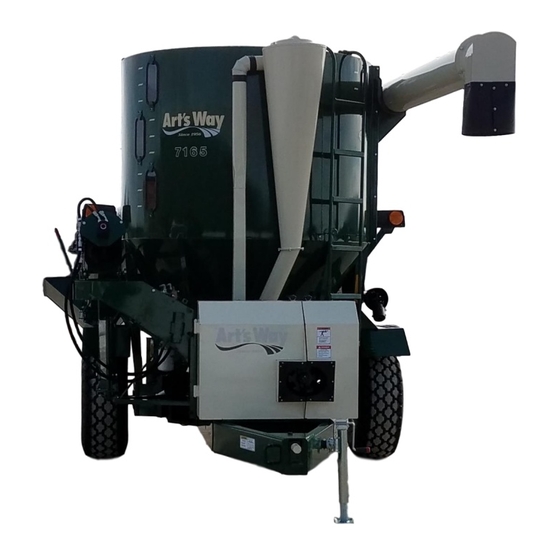
INTRODUCTION Figure 4 - Model 7165 With Auger Feeder (A – PTO Driveline; B – Hammer Mill; C – Mixing Tank; D – Dust Collector; E – Supplemental Hopper; F – Unloading Auger; G – Viewing Windows; H – Auger Feeder). - Page 17 LOADED MIXING TANK LID WHILE PTO ENGAGED TRACTOR RUNNING. Many convenient features are standard equipment on the Art’s Way 7165 grinder mixer including: 7165 Figure 5 - Model 7165 With Self-Contained Hydraulics and Auger Feeder. 1. 13.5 x 16.1 tires.
-
Page 18: Prepairing The Grinder Mixer For Operation
PREPAIRING THE GRINDER MIXER FOR OPERATION PREPAIRING THE GRINDER MIXER FOR OPERATION Remove the shipping banding or wire from the Zerk auger feeder (if equipped), rear discharge cover and the unloading tube to saddle at the side of the Outer tank. -
Page 19: Bolts And Nuts
PREPAIRING THE GRINDER MIXER FOR OPERATION OLTS REPARING RACTOR Cap screws, except for shear bolts, used on the The tractor must be equipped with a 540 or 1000 grinder mixer are Grade 5 and if replaced, cap RPM PTO to match the grinder mixer as described screws of equal or greater strength should be used. -
Page 20: Hammer Mill
PREPAIRING THE GINDER MIXER FOR OPERATION lock into the transport position (see Figure 10). Plug 7-Pin connector for lights into tractor Attach the safety chain from the grinder mixer to the receptacle. tractor (see Figure 11). AMMER CAUTION: ALWAYS FOLLOW STATE Make sure the grinder mixer is equipped with a AND LOCAL REGULATIONS REGARDING 1000 RPM drive when operating with a tractor... - Page 21 PREPAIRING THE GRINDER MIXER FOR OPERATION Disconnect the PTO driveline and front shield anchor chain from the tractor and place it on the PTO driveline support bracket (see Figure 13). The PTO driveline support should be tight enough to remain in position when rotated from storage against the frame to use position.
-
Page 22: Operation Of Grinder Mixer
Push in the pin and turn 1/4 turn in either direction to lock it in place. To There are two replaceable wear plates in the 7165 disengage the Hammer Mill, push in the pin, turn Hammer Mill. The position of the upper wear plate 1/4 turn, and release. -
Page 23: Hay Retard Bolts
OPERATION OF GRINDER MIXER TRACTOR PTO ENGAGEMENT DANGER: TO PREVENT DAMAGE TO HAMMER MILL: 1. FRONT EDGE OF LOWER WEAR PLATE SHOULD BE TIGHT AGAINST THROAT PLATE TO PREVENT BUILD UP UNDER WEAR PLATE. 2. KEEP WEAR PLATE BOLTS TIGHT AGAINST THROAT PLATE... -
Page 24: Changing Screens
OPERATION OF GRINDER MIXER Table 2 - Screen Chart. The Table showing the screen sizes may be used as a guide for grinding different types of food (see Table 2). Do not use a finer screen than needed as this will require more power and reduce Mill capacity. -
Page 25: Processing Hay
OPERATION OF GRINDER MIXER add ingredients to the supplement hopper while grinding, this will over load the auger. Figure 23 - Locking Pin and Latch on Hammer Figure 24 - Supplement Hopper Located on Mill Door. Center Rear Right Hand Side of Machine If micro-ingredients are to be added to the feed, the ROCESSING best results are obtained with a pre-mix, or by... -
Page 26: Filling The Mixer Tank
OPERATION OF GRINDER MIXER 165 BU. – APPROXIMATE CAPACITY CALIBRATION – IN POUNDS* Actual weights may vary due to material, moisture, and screen size. Ration weight is not included and is variable. Window Ground Oats Ground Barley Ground Milo Ground Shelled Ground Ear Corn Un-ground Shelled Position... -
Page 27: Discharge Auger Positioning
OPERATION OF GRINDER MIXER After the processing is completed and the desired RACTOR YDRAULIC ELECTOR ALVE ration is in the mixing tank, allow the mixer to Hydraulic lift and swing is accomplished by using operate until it is ready to unload. Run the mixer 2 the tractor’s hydraulic system valves. -
Page 28: D G F
OPERATION OF GRINDER MIXER Figure 30 – Tractor Hydraulics Flow Control Figure 32 – Tractor Hydraulics Actuator Control Valves (Shown with Selector Valve). Box and Mounting Parts. From Control Box Or Scale Indicator ISCHARGE UNCTION When the discharge auger is in position to unload the tank the gate can be open or closed by an Power Plug electric actuator (see Figure 31). -
Page 29: Unloading Auger Hood
UGER PERATION NOTE: The grinder mixer may be equipped with a hydraulic auger feeder. The 7165 standard Auger Feeder utilizes a tube style auger for optimum loading of grains/supplements. The trough auger is an option that can be field installed for use with ear corn. -
Page 30: Auger Feed Positioner
OPERATION OF GRINDER MIXER NOTE: If a more accurate reading is desired and the machine is equipped with an electronic scale, DO NOT allow the auger feeder to rest on the ground. Place it in the desired position and set the swing brake (see Figure 39). -
Page 31: A F Plp
OPERATION OF GRINDER MIXER Figure 43 - Hydraulic Auger Feeder Controls (Shown in ON/RUN Position): Throttle Controls Figure 41 – Auger Feeder Positioner Operation (White Arrows) and Emergency Shutoff (Red (Ear Corn Auger Feeder Shown). Arrows). UGER OSITIONER OCKING LATE Figure 44 - Hydraulic Auger Feeder Control - Shown in Full ON/RUN Position (See Arrow). - Page 32 OPERATION OF GRINDER MIXER Figure 45 - Hydraulic Auger Feeder Selector Valve Lever is in the IN Position – Discharge Auger).
-
Page 33: Grinder Mixer Adjustments
GRINDER MIXER ADJUSTMENTS GRINDER MIXER ADJUSTMENTS CAUTION: MAKE ADJUSTMENTS WHILE MACHINE IS IN OPERATION AUGER/SUPPLEMENT. RIVE HAIN DJUSTMENTS The Mill to mixer auger/supplement hopper drive chain and the discharge auger drive chain are tensioned with an idler sprocket (see Figure 46). Adjust the chain tension to 1/2 inch total deflection by positioning the idler sprocket. -
Page 34: Hammer Mill Door
GRINDER MIXER ADJUSTMENTS IMPORTANT: Proper alignment of the pulleys must be maintained when adjusting belt tension. Belts should be checked periodically for proper tension and alignment, especially when the machine is new or when a new set of belts are installed (see Figure 51). -
Page 35: Hydraulic Swing Adjustment
GRINDER MIXER ADJUSTMENTS YDRAULIC WING DJUSTMENT WIVEL DJUSTMENT If any problem is encountered with the hydraulic Loosen the bolts holding the Lower Stop (see swing adjustment drive, adjust and/or check as Figure 55). (Do not loosen the bolts for Upper Stop, follows (see Figure 53): it is fixed.) Adjust the Lower Stop so it makes contact with the Upper Stop when the Discharge... -
Page 36: Discharge Auger Height Settings
46° max. to -27° min. configuration (for lower storage bins and feed troughs) for the Discharge Auger elevations. NOTE: The 7165 is shipped from the factory in the upper configuration (see Figure 58). If Discharge Auger needs to be changed to the lower configuration do the following steps (see Figures 58 &... -
Page 37: Open And Closed Center Tractor
GRINDER MIXER ADJUSTMENTS PEN AND LOSED ENTER RACTOR HEEL EARINGS YDRAULICS Raise the frame and make sure it is blocked As the standard, this machine is equipped for securely so the wheels may turn freely (make sure tractor “Open Center” hydraulic operation. If the the opposite wheel is also blocked securely). -
Page 38: Lubrication
LUBRICATION LUBRICATION CAUTION: SHUT OFF POWER SOURCE, PLACE POCKET, DISCONNECT IMPLEMENT INPUT DRIVELINE BEFORE LUBRICATING MACHINE. The grinder mixer is designed to require a minimum amount of lubrication. The points that are to be lubricated should be serviced regularly at the specified intervals listed in this manual. -
Page 39: Drive Belt Idler Tensioner
LUBRICATION AMMER NGAGING Periodically oil the sliding pin that engages the large Hammer Mill drive pulley. Use light engine oil for lubrication (see Figure 68). Figure 65 – Front Cylinder Shaft Bearing (See Arrow) (Shields Removed for Clarity). Figure 68 – Hammer Mill Engaging Pin (Shields Removed for Clarity). -
Page 40: Chains
LUBRICATION the inside located in the upper side of lower the strand (see Figure 73). The chains should also be cleaned regularly. Remove the chains and dip or soak them in kerosene or parts cleaning solvent. Once the chains have been cleaned, dry and oil them thoroughly. -
Page 41: Lower Vertical Mixing Auger
LUBRICATION PPER ERTICAL IXING UGER Check Plug Grease the upper vertical mixing auger bearing weekly or every 10 hours of operation with SAE multi-purpose type grease. Access to this bearing can be gained through the top of the mixing tank (see Figure 78). -
Page 42: Wheels
LUBRICATION Figure 80 – Discharge Pivot Pin. HEELS Remove, clean, and repack the wheel bearings once a year or every 100 hours of operation using SAE multi-purpose type grease (See Figure 81). Figure 81 - Wheel Bearing Lubrication. -
Page 43: Service
SERVICE SERVICE Warning: using a harder bolt in a shear bolt ORQUE PECIFICATIONS location can cause damage to vital and more expensive drive components. CAUTION: DISENGAGE ALL DRIVES, SHUT OFF POWER SOURCE, PLACE KEY IN POCKET, AND DISCONNECT PTO DRIVELINE PRIOR TO SERVICING GRINDER MIXER. -
Page 44: Replacement O F Worn O R Damaged
SERVICE EPLACEMENT AMAGED AMMERS Hammers must be replaced in pairs to maintain proper balance. This is accomplished by replacing the hammers opposite of each other (180 degrees apart) using a matched pair. EVERSING AMMERS CAUTION: SHUT OFF POWER SOURCE, PLACE KEY IN POCKET, DISENGAGE ALL DRIVES, WAIT TILL ROTATING PARTS HAVE COMPLETELY STOPPED Figure 85 - Sprocket Alignment. -
Page 45: Standard Spacing For 96 Hammers
SERVICE STANDARD SPACING FOR 96 HAMMERS Short Bushing Hammer Assembly of rods 2 & 4 Plate Long Bushing Hammer Plate Hammer Rod 3 Rod 2 Rod 4 Rod 1 Hammer Hammer Short Bushing Assembly of rods 1 & 3 Long Bushing Hammer Figure 87 - Proper Hammer Spacing for 96 Hammers (26 Inch Hammer Mill). -
Page 46: Main Drive Belt Replacement
NOISES DETERMINE CAUSE OF NOISE BEFORE RESTARTING. There are two replaceable wear plates in the 7165 Hammer Mill (see Figure 93 & 94). Upper Wear Plate: Unscrew the 4-bolts (2 on each side) that hold it in place, then remove the hood and slide the wear plate out toward the throat of the Figure 92, Detail B). - Page 47 SERVICE place and/or grind any welds holding the front edge down to the throat plate (see Figure 94). DANGER: TO PREVENT DAMAGE TO HAMMER MILL: To replace the wear plate, slide it in making sure that it is fully seated. It must be tight against the 1.
-
Page 48: Troubleshooting Guide
TROUBLESHOOTING GUIDE TROUBLESHOOTING GUIDE The majority of difficulties are caused by improper adjustments. When you encounter trouble, perform a systematic check of all possible adjustments using the chart that follows. If difficulties cannot be corrected by making the adjustments that follow, consult your local Art’s Way authorized dealer for further assistance. TROUBLE POSSIBLE CAUSE POSSIBLE REMEDY... - Page 49 TROUBLESHOOTING GUIDE TROUBLE POSSIBLE CAUSE POSSIBLE REMEDY Mill will run but the mixing auger does Repair the cause of the bolt(s) shearing and Bolt(s) sheared in the drive not run replace bolt(s) Discharge auger running, but the feed Mixer tank gate is closed Open the mixer tank gate is not unloading Gate actuator is not working...
-
Page 50: Self-Contained: Introduction
7165 with self- This system can be used with any tractor that can contained hydraulics. Take time to read and maintain a rated PTO speed when grinding. -
Page 51: Preparing The Grinder Mixer
SELF-CONTAINED replacement. It also blinks when there is a problem REPARING THE RINDER IXER with the system in the form of an error code. Refer Electrical Components to the ERROR CODE CHART in the SELF CONTAINED: TROUBLE SHOOTING portion of Linear Actuator is shipped in Supplement Hopper. -
Page 52: Control
SELF-CONTAINED between pushing the #8 button and pressing the reprogrammed to respond to the new Remote POWER (send) button. Control. YNCHRONIZING ECEIVER TO EMOTE Power Indicator ‘Red’ ONTROL Signal If the Remote Control needs to be synchronized to Indicator the Receiver do the following: ‘Green’... -
Page 53: Complete Control Box As Backup
EMOTE ONTROL Adjustable flow control valves to control the rate of 7165 Grinder Mixer units equipped with the swing are located in hydraulic control valve. For Complete Control Box (see Figure 99) need to flip faster swing, turn control screw out. Set both valves the Mode Switch at the lower left hand corner of at approximately the same setting. -
Page 54: Self-Contained: Operation
SELF-CONTAINED SELF-CONTAINED: OPERATION CAUTION: ALWAYS OPERATE PTO AT SPEED WHICH MACHINE EQUIPED: 1000 RPM. NOTE SPEED DECAL ON FRONT SHIELD. The grinder mixer should be run at a slow idle for a few minutes when the temperature drops below 0° F to allow the hydraulic oil to warm up. - Page 55 SELF-CONTAINED IMPORTANT: Hydraulic cooler fan needs to be Discharge Discharge operated with a good working charged 12 volt Start electrical system (i.e. alternator) to function properly. Discharge Gate Left Open WARNING: DISENGAGE PTO, SHUT OFF POWER SOURCE, AND PLACE KEY IN POCKET BEFORE ATTEMPTING TO CLEAR BLOCKED AUGER.
-
Page 56: D A Lca
To adjust the speed at which the lift cylinder raises or lowers the discharge auger, loosen the lock nut The manifold valve on the 7165 GM is equipped and turn the valve flow adjustment screw with 1/4” with an electronic soft shift controller (see Figures hex wrench for discharge lift (NV) or 3/16”... - Page 57 SELF-CONTAINED a “forward/pulling” direction up to approximately 10 minutes or until the oil has cooled below the 115°F 12V Cooler setting. If the fan runs the full 10 minutes, it will automatically shut down “reverse/pushing” direction for approximately 30 seconds to help aid in cleaning the oil cooler fins from dust/debris which may be affecting air movement.
-
Page 58: Self-Contained: Adjustment/Service & Lubrication
SELF-CONTAINED SELF-CONTAINED: ADJUSTMENT/SERVICE & LUBRICATION CAUTION: TURN OFF POWER SOURCE, PLACE POCKET, DISCONNECT IMPLEMENT INPUT DRIVELINE BEFORE CLEANING, ADJUSTING, LUBRICATING MACHINE. RIVE HAIN Adjust mounting bracket of hydraulic pump so that the sheave on the Hammer Mill jack shaft and sheave on the hydraulic pump are running in-line. -
Page 59: Filler /Breather Filter
SELF-CONTAINED A suction strainer is located in the suction port of the hydraulic reservoir tank. Periodically remove NOTE: New hydraulic oil is not necessarily free and clean it with compressed air, blowing from from contaminants. New hydraulic oil straight from inside out. -
Page 60: Hydraulic Cooler Maintenance
SELF-CONTAINED Electric fan motor has sealed bearings and will not YDRAULIC OOLER AINTENANCE require any lubrication. EXTERNAL CLEANING Visually check the cooling fins daily for excessive NOTE: Avoid running machine in wet conditions or dust/debris build up which may decrease the with water/moister in the oil cooler. -
Page 61: Self Contained: Troubleshooting Guide
SELF-CONTAINED: TROUBLESHOOTING SELF CONTAINED: TROUBLESHOOTING GUIDE The majority of difficulties are caused by improper adjustments. When you encounter trouble, perform a systematic check of all possible adjustments using the chart that follows. If difficulties cannot be corrected by making the adjustments that follow, consult your local Art’s Way authorized dealer for further assistance. - Page 62 SELF-CONTAINED: TROUBLESHOOTING TROUBLE POSSIBLE CAUSE POSSIBLE REMEDY No functions work on wireless remote Wireless remote control is turned off Turn power on wireless remote control control Batteries in wireless remote control are Recharge internal batteries on Macro-remote weak or drained control Something is blocking signal from Move to location with clear line of site from...
- Page 63 SELF-CONTAINED: TROUBLESHOOTING Hydraulic fluid leak Check all fittings and hoses for leaks Relief bypass in manifold valve set at Increase relief valve pressure too low of pressure Contamination in valves Remove and clean cartridge valves Faulty relief valve Replace relief valve Adjustable valves closed Open valves Air in hydraulic lines...
-
Page 64: Self Contained: Remote Control Error Codes
SELF-CONTAINED: TROUBLESHOOTING SELF CONTAINED: REMOTE CONTROL ERROR CODES Count the number of blinks on the receiver or the wireless remote control red LED. ERROR CODE PROBABLE CAUSE 1 Blink Radio signal problem 2 Blink Short or open connection at output 1 (White Wire to Receiver) 3 Blink Short or open connection at output 2 (Green Wire to Receiver) 4 Blink... -
Page 65: Attachments
ATTACHMENTS ATTACHMENTS LECTRONIC CALE TTACHMENT A solid state electronic scale attachment, digital type, is available for your grinder mixer. The scale attachment consists of weigh bar sensors mounted on the grinder mixers axle spindles and hitch. They are electronically connected to the indicator bars. The indicator alarm system is available with the Figure 115 - Folding Auger Extension. -
Page 66: Roll Feed Adjustment
ATTACHMENTS CAUTION: NEVER FORCE MATERIAL INTO ROLL FEED WITH STICK OR WITH HANDS. BE ESPECIALLY CAREFUL WHEN FEEDING SLICES HAY, ALWAYS ALLOWING ROLL FEED TO PULL HAY INTO MILL. The hydraulic roll feed is connected in series with the hydraulic auger feeder. A separate flow control valve allows separate speed control for the roll feed. -
Page 67: Specifications
SPECIFICATIONS SPECIFICATIONS ANK AND RAME • Capacity of mixing tank: ..................165 bu. /206 cu. ft. • Height (variable with tire size): ................126 inches. • Width without auger feeder: ..................111 inches. • Overall length:......................175 inches. • Weight: ........................5150 lbs. ISCHARGE UGER •... -
Page 68: Specifications: Self-Contained Hydraulics
SPECIFICATIONS SPECIFICATIONS: SELF-CONTAINED HYDRAULICS YDRAULIC OTORS Auger Feeder/Roll Feeder • Type: Gear Driven Positive Displacement • Type: Gear, low speed high torque • Displacement: 3.869 cu. in. per revolution • Displacement: 11.3 cu. in. per revolution • Flow (GPM): 15.6 gallons per minute @ 1000 •... - Page 69 SPECIFICATIONS • Port Sizes: P: -12 ORB (1-1/16-12 SAE) Needle Valve NV (Manifold Valve Assembly) • Material: Steel T: -12 ORB (1-1/16-12 SAE) LD,UD: -10 ORB (7/8-14 SAE) • Type: Cartridge-style, variable orifice, hydraulic flow restrictor A1,A2,D1,D2,S1,S2: -8 ORB (3/4-16 SAE) •...
-
Page 70: Electric Actuator
SPECIFICATIONS Pressure Gauges G1 & G2 (Manifold Valve IRELESS EMOTE ONTROL Assembly) • Power Supply: Internal rechargeable lithium ion • Material: Steel battery. Battery Life continuous operation: 35- 40 hours. • Type: 2-1/2 inch stem mount • Operating Temperature - Radio: -40°F to +185°F •... -
Page 71: Schematics: Tractor Hydraulics
SPECIFICATIONS SCHEMATICS: TRACTOR HYDRAULICS... -
Page 72: Schematics: Self-Contained Hydraulics
SCHEMATICS SCHEMATICS: SELF-CONTAINED HYDRAULICS... -
Page 73: Schematics: Self-Contained Wiring
SPECIFICATIONS SCHEMATICS: SELF-CONTAINED WIRING CONTROL BOX WITH 4 FT. WIRING HARNESS WIRING HARNESS VALVE BANK, MANIFOLD, & ACTUATOR... -
Page 74: Schematics: Self-Contained Wiring
SCHEMATICS SCHEMATICS: SELF-CONTAINED WIRING RECEIVER 8-OUTPUT OPTIONAL 20 FT. WIRE HARNESS EXTENSION... -
Page 75: Art's-Way Manufacturing Co., Inc
ART’S-WAY MANUFACTURING CO., INC. TECHNICAL MANUALS Manuals are available from your local dealer or Art’s-Way Manufacturing Co., Inc. for the operation, service, and repair of your machine. For prompt convenient service, contact your local dealer for assistance in obtaining the manuals for your machine. Your local dealer can expedite your order for operator manuals, illustrated parts catalogs, service manuals, and maintenance records.
Need help?
Do you have a question about the 7165 and is the answer not in the manual?
Questions and answers