
Related Manuals for Art's-Way Manufacturing 6812A


Summary of Contents for Art's-Way Manufacturing 6812A
- Page 1 Art’s-Way Manufacturing Co., Inc. Model 6812A Sugar Beet Harvester Operator’s Manual 555040 Issued Apr 2007...
- Page 2 This symbol means ATTENTION! BECOME ALERT! YOUR SAFETY IS INVOLVED. The message that follows the symbol contains important information about your safety. Carefully read the message. Make sure you fully understand the causes of possible injury or death. IF THIS MACHINE IS USED BY AN EMPLOYEE, IS LOANED, OR IS RENTED, MAKE SURE THAT THE OPERATOR UNDERSTANDS THE TWO INSTRUCTIONS BELOW.
-
Page 3: To The Owner
This manual contains operating instructions for your 6812A Sugar Beet Harvester only. Any mention of other machinery in this manual other than the 6812A Sugar Beet Harvester is for reference only. This manual does not replace nor is it to be... -
Page 4: Parts & Service
PARTS & SERVICE PARTS & SERVICE As the purchaser of your new harvester, it is very important to consider the following factors: A. Original Quality B. Availability of Service Parts C. Availability of Adequate Service Facilities Art’s-Way Manufacturing Co., Inc. has an excellent dealership network ready to answer any questions you may have about your harvester. -
Page 5: Table Of Contents
TABLE OF CONTENTS TABLE OF CONTENTS TO THE OWNER ..........1 HARVESTER ADJUSTMENTS ......29 PECIFICATIONS ESIGN UBJECT HANGE (PTO) – C ..29 OWER AKEOFF ONSTANT ELOCITY ............1 ITHOUT OTICE ........29 ARVESTER YLINDERS ’ ., I ANUFACTURING TATEMENT .......29 OWFINDER TEERING YLINDER... - Page 6 TABLE OF CONTENTS Lifter Struts ............58 Lifter Wheel Scrapers ........58 Paddle Shaft and Drive........58 Gearboxes (Qty 2 or 3) ........58 Conveyor Roll Bed and Drive......58 Grab Rolls and Drive ......... 58 Offloading Boom ..........58 Tank..............
-
Page 7: Limited Warranty
LIMITED WARRANTY LIMITED WARRANTY Art’s-Way Manufacturing Co., Inc. warrants the products it sells to be free from defects in material and workmanship for a period of one (1) year after the date of delivery to the first (original) purchaser, subject to the following conditions: •... -
Page 8: Safety First
Please be alert whenever you see this symbol in the manuals or on your harvester. Art’s-Way Manufacturing Co., Inc. strives to make our equipment as safe as possible. The Art’s-Way 6812A Sugar Beet Harvester conforms to applicable safety standards at the time of manufacturing. A safety conscious equipment operator makes an effective accident-prevention program complete. -
Page 9: Safety Guidelines
SAFETY GUIDELINES SAFETY GUIDELINES • Keep all bystanders, especially children, away from Remember: the harvester while in operation. “The Best Operator is a Safe Operator” • Do not allow riders while the harvester is in operation. • Do not attempt to unclog, clean, or adjust the CAUTION: READ AND UNDERSTAND THE harvester while it is running. -
Page 10: Transportation Safety
SAFETY GUIDELINES • Wear proper hand and eye protection when searching AFETY for a high-pressure hydraulic leak. Use a piece of • Have only a qualified tire dealer or tire repair service wood or cardboard as a backstop instead of hands to perform tire repairs. -
Page 11: Safety Decals
SAFETY DECALS SAFETY DECALS & I ECAL OCATIONS DENTIFICATION The different types of safety decals for your Sugar Beet Harvester are illustrated on the following pages. Please familiarize yourself with the appearance of each decal, the warning it describes, and the area where it is located on the harvester. Safety awareness is the responsibility of each operator of the harvester. - Page 12 SAFETY DECALS...
- Page 13 SAFETY DECALS...
- Page 14 SAFETY DECALS Figure 6 - Header Safety Decals...
- Page 15 SAFETY DECALS...
- Page 16 SAFETY DECALS...
-
Page 17: Harvester Overview
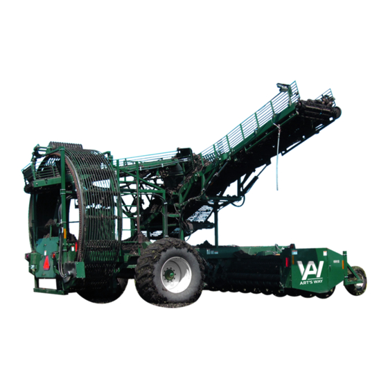
Whenever the term(s) “left-hand” and “right-hand” are used, it should be understood that this means you are standing behind the harvester and facing the direction of forward travel. Figure 7 - 6812A Sugar Beet Harvester The wheel elevator, set slightly lower than the main... -
Page 18: Electrical System
HARVESTER OVERVIEW The main structures of the harvester are: • Frame • Tongue • Carrier Wheels • Header (4 different configurations) 6 row header – 28 or 30 inch [71.12 to 76.2 cm] 8 row header – 22 inch [55.88 cm]. 8 row header –... -
Page 19: Harvester Self-Contained Hydraulic System
HARVESTER OVERVIEW While the rowfinder and the steering cylinder have their ECHANICAL YSTEM own connections, both systems are connected. This allows the rowfinder to independently operate the steering cylinder as well as allow the operator to Drive Shafts And Gearbox manually adjust the steering cylinder. - Page 20 HARVESTER OVERVIEW Figure 13 - Harvester Right-Hand Belt Drive (Rear Figure 16 - Harvester Grab Roller Forward Belt Drive Grabroll Option Shown). Spring Tensioner. Figure 17 - Wide Heads, LH (8 Row 30 And 12 Row 22) (Rear Grabroll Option Shown) Figure 14 - Harvester Left-Hand Chain &...
- Page 21 HARVESTER OVERVIEW Figure 20 – Draper Chain Drives, Short Conveyor Shown. Figure 18 - Truck Conveyor Sprocket and Drive Chain. Figure 19 - Wheel Elevator Motor Sprocket and Drive Chain.
-
Page 22: Tractor/Harvester Connection
TRACTOR/HARVESTER CONNECTION TRACTOR/HARVESTER CONNECTION RACTOR EQUIREMENTS The Art’s-Way 6812A Sugar Beet Harvester is designed to be used by large agricultural tractors. To ensure good performance, Art’s-Way recommends that the harvester be operated by a tractor with 200 PTO horsepower or larger. -
Page 23: Tractor/Harvester Connection
TRACTOR/HARVESTER CONNECTION 16. Check the hydraulic fluid levels of the tractor. Verify hydraulic fluid levels are at the proper levels. CAUTION : KEEP CLEAR OF THE MACHINE Service the hydraulic systems as needed. AS IT SHIFTS SIDEWAYS. 17. Cycle the lift cylinders and observe the lift height. Position the front bolt-on hitch to obtain the desired lift height, while still allowing adequate penetration 28. -
Page 24: Field Operations
FIELD OPERATIONS FIELD OPERATIONS Harvester Lift Cylinder CAUTION: KEEP WELL CLEAR OF MOVING PARTS. BE SURE TO SHUT OFF TRACTOR AND PLACE KEY IN POCKET WHILE MAKING ADJUSTMENTS. WAIT FOR ALL MOVEMENT STOP BEFORE APPROACHING MACHINE. PERATING PEEDS It is recommended the harvester be operated at a speed between 3.5 and 4.5 mph [5.6 and 7.2 km/h]. -
Page 25: Header
FIELD OPERATIONS The rowfinder assists in keeping the harvester aligned The lifter wheels dig into the ground and lift both beet with the rows. The feeler arms rest astride the row and and dirt upwards towards the paddle assemblies. The follow the line of beets, sensing any changes in the lifter wheels attach to the lifter wheel struts, which come direction of the row or the position of the harvester. - Page 26 FIELD OPERATIONS Paddle Assemblies If the poly rolls have been selected as an option, the spacing can be adjusted to an open or closed position. Poly rolls are set to the closed position at the factory. To move the rolls to the open position, the outside bearings must be rotated backwards and fastened into the new bolt holes.
-
Page 27: Short Conveyor
FIELD OPERATIONS maintained. Additional chain drives are required for the front smooth or star roll and the left-hand diverter roll on the left-hand side for the 6 Row 30 and 8 Row 22. Short Conveyor Figure 33 - Header Left-Hand Drive With Diverter Grab Roll Option (12 Row 22 And 8 Row 30). -
Page 28: Wheel Elevator
FIELD OPERATIONS The wheel elevator transports the beets from the harvester conveyor up to the holding tank conveyor. The beets are carried up to the holding tank conveyor as the wheel elevator revolves clockwise. To make sure beets do not fall downward as the wheel elevator rotates, a retainer applies spring pressure outward against the wheel elevator. -
Page 29: Stripper
FIELD OPERATIONS Stripper Figure 45 - Transfer Conveyor Pivot Cylinder A unique feature of the transfer conveyor is the ability Figure 42 - Wheel Elevator Stripper. for the conveyor to pivot left and right to ensure the The stripper is an adjustable device with several disks holding tank is filled totally and the beets have a which help clear the wheel elevator of any rocks, trash, minimum drop into the tank. -
Page 30: Truck Boom
FIELD OPERATIONS Truck Boom Figure 47 - Truck Boom The truck boom is the outer section of the offloading conveyor. The truck boom has the ability to raise and lower and is selected by operator using a small switch attached on the hydraulic lever. The truck boom must be raised if the operator is going to be transferring the harvested beets to a truck on the right-hand side of the harvester. -
Page 31: Harvester Adjustments
HARVESTER ADJUSTMENTS HARVESTER ADJUSTMENTS The rowfinder is adjustable to accommodate beet size, CAUTION: KEEP A SAFE DISTANCE AWAY beet height, operating depth and soil conditions. Correct FROM MOVING PARTS. BE SURE TO SHUT adjustment of the rowfinder and a good understanding TRACTOR PLACE of the importance of each adjustment will provide... -
Page 32: Feeler Arm Down Pressure
HARVESTER ADJUSTMENTS should be about 3 inches [7.62 cm] above the rims of Pinch Point Width the lifter wheels when operating in the rows. To change the rowfinder height by more than 1 inch [2.54 cm], loosen bolts attaching the rowfinder vertical tube to the support plate and move to the desired operating height. -
Page 33: Scrapers
HARVESTER ADJUSTMENTS Flex Struts Scrapers Figure 54 - Header Lifter Wheel Scraper Adjustments. Shim the scrapers so they just clear the hub and lifter 3.25 wheel. Operating Depth As a starting point, the lifter wheels should be set to dig approximately 2 to 3.5 inches [5.08 to 8.255 mm] deep. -
Page 34: Barriers And Covers
HARVESTER ADJUSTMENTS The rubber paddles may be removed if desired (except when flex struts are used). If removed, reposition the paddle shaft by lowering it to the bottom set of the bearing holes. This will keep the paddle tips in their correct relationship. -
Page 35: Paddle Shaft Slip Clutch
HARVESTER ADJUSTMENTS Friction Slip Clutch Paddle Shaft Slip Clutch There are two paddle shaft slip clutches used on the header, a jaw or friction type. The jaw type paddle shaft slip clutch is used with steel rollers. The friction clutch is used with the polyethylene coated rollers. -
Page 36: Short Conveyor
HARVESTER ADJUSTMENTS On harvesters with the 12 row 22 inch or 8 row 30 inch, HORT ONVEYOR install the front header gage wheels on the front corners of the header with the clamps provided. The suggested setting is 3.5 inches (8.89 cm) (4 x 4) with the lifter wheels on concrete. -
Page 37: Wheel Elevator Retainer
HARVESTER ADJUSTMENTS After the length of the cushions is set, the spacing can be set with a single 1 inch [2.54 cm] bolts to the front and rear on the left-hand side. Always maintain a wider gap at the back. Open the rolls as wide as possible without loosing beets. -
Page 38: Wheel Elevator
HARVESTER ADJUSTMENTS HEEL LEVATOR The recommended speed of the wheel elevator is 11 rpm. In some conditions a slower speed of 9 to 10 rpm may be desirable. Adjust the flow control to control the wheel elevator speed. Wheel drive chain to hydraulic motor. UPPER LOWER Figure 72 - Wheel Elevator Retainer Springs. -
Page 39: Truck Conveyor
HARVESTER ADJUSTMENTS RUCK ONVEYOR C) Rowfinder Operation (Valve and Cylinder) 1) If a power beyond circuit is used, it should be connected to this function. Check with dealer for proper connection. 2) This circuit normally requires 5 to 7 gpm to operate. -
Page 40: Tires
BEADS ARE NOT SEATED WHEN THE IRES MAXIMUM RECOMMENDED PRESSURE IS REACHED, DEFLATE, REPOSITION TIRE, Frequently check tire pressures. Lists recommended RELUBRICATE BEAD, AND REINFLATE. pressure for tires used on 6812A Beet Harvester. DETAILED AGRICULTURAL TIRE -24 psi Recommended INSTALLING INSTRUCTIONS, INCLUDING 24.5-32 –... - Page 41 TROUBLE SHOOTING GUIDE Figure 76 - Tractor/Harvester Hydraulic System...
- Page 42 TROUBLE SHOOTING GUIDE Figure 77 - Harvester Self-Contained Hydraulic System...
-
Page 43: Trouble Shooting Guide
TROUBLE SHOOTING GUIDE TROUBLE SHOOTING GUIDE The Art’s-Way 6812A Sugar Beet Harvester is designed to provide simple and reliable operation throughout beet harvest. Its full range of adjustments ensures efficiency in varying operating conditions. If you encounter a problem with the Harvester, check this Trouble Shooting section for possible cause and solutions. If you have a problem that is not covered in this section, please call your local Art’s-Way dealer for assistance. - Page 44 TROUBLE SHOOTING GUIDE Problem Possible Cause Possible Remedy Lose small beets Conditions suitable for utilization of Install close-ups close-ups Grabroll spacing too wide Reduce gap of grabroll pairs Ground speed too slow Increase ground speed – this may help get the beets to the paddles and onto the cleaning bed Lifter wheels too far apart Space the wheels closer together...
-
Page 45: Owfinder
TROUBLE SHOOTING GUIDE Problem Possible Cause Possible Remedy Beet plugging cleaning bed PTO speed too slow Increase PTO speed to a minimum of 950 RPM Grabroll spacing wrong between Adjust grabrolls must be pairs further apart at discharge end Loading too much dirt Raise digging depth of machine Flighting and transfer areas of spiral... -
Page 46: Lubrication Schedule
LUBRICATION SCHEDULE LUBRICATION SCHEDULE IMPORTANT: Failure to frequently grease the CV center housing and telescoping members will ENERAL reduce the life of the CV. Economical and efficient operation of the Harvester B) Hitch, Input Drive and Rowfinder. depends upon the regular and proper lubrication of all moving parts with quality lubricant. - Page 47 LUBRICATION SCHEDULE D) Header Lifter Wheels H) Elevator and Tank Area. 1) Lifter wheel hubs every 20 to 50 hours 1) Flange block bearings drive and idler end of depending on conditions. elevators, short conveyor, transfer conveyor, and truck conveyor E) Right Hand drives.
-
Page 48: Quick Reference B Y Hour
LUBRICATION SCHEDULE UICK EFERENCE A) Every 8 hours 1) CV PTO. If making frequent or sharp turns, grease the CV center housing at four (4) hour intervals. 2) Cross and Bearings until grease is purged around the seal (2 to 4 pumps). 3) CV center Housing until grease is evident around the center section disk (6 to 12 pumps). -
Page 49: Seasonal Storage
SEASONAL STORAGE SEASONAL STORAGE Proper storage of the harvester will increase the service life and make it easier to place it back into service at the beginning of the next season. REPARING ARVESTER TORAGE ETURNING ARVESTER TORAGE Store harvester in a dry place. Replace wheels, if they were removed, and remove Squirt diesel fuel on seals of bearing prior to blocking. -
Page 50: Transporting The Harvester
TRANSPORTING THE HARVESTER TRANSPORTING THE HARVESTER CAUTION: IT IS THE RESPONSIBILITY OF THE OPERATOR TO KNOW THE LIGHTING AND MARKING REQUIREMENTS OF LOCAL HIGHWAY AUTHORITIES. ROAD HAZARD LIGHTS PROVIDED WITH THIS HARVESTER CONFORM TO CURRENT ASAE STANDARD 279.10 LIGHTING MARKING AGRICULTURAL EQUIPMENT HIGHWAYS. -
Page 51: Dealer Assembly Instructions
TRANSPORTING THE HARVESTER DEALER ASSEMBLY INSTRUCTIONS Installation of wheel and tire assemblies. ELIVERY Adjust the axle to the outer most position. Install the left- and right-hand wheel and tire CAUTION: THE HARVESTER HAS A TOTAL assemblies on the hub and spindle assembly. WEIGHT RANGING FROM... - Page 52 DEALER ASSEMBLY INSTRUCTIONS Prepare head to install to basic unit. For the 12 Row 22 head, rotate the head back to its correct position and remove the shipping stands. The 12 Row 22 head will also have the rear grate rods removed. Install in the diagaonal position.
- Page 53 TRANSPORTING THE HARVESTER Lift the short conveyor into position on the angles over the grab rolls and secure to the front position with bolts shown. Position so rods of draper chain are slightly lower than the top of the roll flighting. Then so the riser links clear the spiral of the roll 1/8 to 3/16.
- Page 54 DEALER ASSEMBLY INSTRUCTIONS Figure 95 – Short Conveyor Grate And Pin Assembly UNITS PART NUMBER NOMENCLATURE ITEM ASSY 539020-170 SHORT CONVEYOR GRATE AND PIN ASSEMBLY 559700 GRATE WLDT, LH 559710 GRATE WLDT, RH 347540 ROD, GRATE 0.5 X 14.75 559750 CHANNEL, LH SHORT 264190 ROD, GRATE 0.5 X 16.50...
- Page 55 TRANSPORTING THE HARVESTER Figure 96 - Wheel Mounts, Front (Optional) Figure 99 - Draper Chain Routing Figure 97 - Front Header Wheels Height Install the grates on the offloading conveyor using 0.5 x 3.75 inch (1.27 x 9.525 cm) HHCS, two (2) flat washers, lock washer &...
- Page 56 DEALER ASSEMBLY INSTRUCTIONS 17. The self contained system runs three (3) hydraulic 14. Installing the wheel elevator stripper. motors. The short conveyor and transfer conveyor Position the stripper so it is the desired depth are connected in series. The wheel elevator is into the ferris wheel, this will most likely be 4 to driven by the second circuit.
-
Page 57: Harvester Adjustments
TRANSPORTING THE HARVESTER A 44 inch (111.76 cm) fixed boom extension is provided for the 8-row 30 inch and 12-row 22 inch head. The belted draper chain for the truck conveyor and tank is shipped loose. Remove the hoses from the hydraulic motor and remove the truck conveyor from the tank. - Page 58 DEALER ASSEMBLY INSTRUCTIONS Figure 107 – 44 Inch Fixed Boom Extension Installation (526800) UNITS PART NUMBER NOMENCLATURE ITEM ASSY 526800 BOOM EXTENSION 12R22 (44 INCH) 526830 HOSE, HYD. 5/8 X 44 524010 BOOM WLDT., 44 INCH EXT. 524100 ARM WLDT., EXT. SUPT. 526570 CHAIN, BELTED 50MM 526560...
-
Page 59: Pre -Delivery Test Run
TRANSPORTING THE HARVESTER 12. Shut down the tractor, allow all moving parts to come to a complete stop. ELIVERY 13. Check the harvester for any loose hardware CAUTION: BEFORE CONDUCTING review all drives. PRE-DELIVERY TEST RUN, KEEP ALL CHILDREN BYSTANDERS AWAY 14. -
Page 60: Specifications
SPECIFICATIONS SPECIFICATIONS ENERAL Paddle Shaft and Drive • Type – three steel per row Model • Drive – Heavy #80H roller chain with heavy • duty slip clutch 6, 8, or 12 Row Tank Type Harvester Gearboxes (Qty 2 or 3) Overall Dimensions •... - Page 61 SPECIFICATIONS Torque Specification Guide TTACHMENTS (SAE Grade 5 Coarse Thread) Rowfinder Clamp • Size Plain Plated To keep the harvester on the row Load 1/4 - 20(.250) 2,205 8 ft. lbs. 76 in. lbs. Lifter Wheel Close-up (Optional) • To prevent loss of small beets through lifter 5/16 –...
- Page 62 NOTES...
- Page 63 ART’S-WAY MANUFACTURING CO., INC. TECHNICAL MANUALS Manuals are available from your local dealer or Art’s-Way Manufacturing Co., Inc. for the operation, service, and repair of your machine. For prompt convenient service, contact your local dealer for assistance in obtaining the manuals for your machine. Your local dealer can expedite your order for operator manuals, illustrated parts catalogs, service manuals, and maintenance records.
- Page 64 Produced And Published In The U.S.A. By CPS DYNAMICS, LLC PO Box 9007 Art’s-Way Manufacturing Co., Inc. Wichita, KS 67205 www.cpsdynamics.com Hwy 9 West – PO Box 288 Armstrong, IA. 50515 U.S.A...
Need help?
Do you have a question about the 6812A and is the answer not in the manual?
Questions and answers