
Subscribe to Our Youtube Channel
Related Manuals for Hussmann Scroll Plus Fibertronic 401789


Summary of Contents for Hussmann Scroll Plus Fibertronic 401789
- Page 1 Contents ® Tables Figures Scroll Plus ™ Fibertronic ™ ® P/N 401789 Installation and Service Manual...
- Page 2 Contents Revised August 1, 1996 Tables Figures SAFETY TIPS Being Safe is Your Responsibility. Wear proper eye protection whenever working. Know whether a circuit is open at the power supply or not. Remove all power before Wear proper hearing protection whenever opening control panels.
- Page 3 Bridgeton, Missouri 63044-2483 (314) 291-2000 Congratulations! With the purchase of Hussmann's Scroll Plus™ Fibertronic™ System, you are receiving equipment designed to provide the finest refrigeration and temperature control for modern supermarket display equipment and coolers. Since the introduction of Hussmann Central Refrigeration Systems, thousands of installations have confirmed our belief that, as with all fine equipment, good installation and proper adjustment are the keys to customer satisfaction.
- Page 4 Contents ® ® Tables Tables Figures Figures Scroll Plus ™ Fibertronic ™ Installation and Service Manual Hussmann Corporation 12999 St. Charles Rock Road Bridgeton, MO 63044-2483 Printed in USA ® P/N 401789 September, 1997...
-
Page 5: Table Of Contents
Branch Line Piping - - - - - - - - - - - - - - - - - - - - - - - - - - - - - - - - - - - - - - - - - - - - - - - - - - - 3-8 P/N 401789 9709 Page iii HUSSMANN CORPORATION • BRIDGETON, MO 63044-2483 (Printed in USA) - Page 6 Electrical and Preliminary Checkout - - - - - - - - - - - - - - - - - - - - - - - - - - - - - - - - - - - - - - - 5-10 P/N 401789 9709 Page iv HUSSMANN CORPORATION • BRIDGETON, MO 63044-2483 (Printed in USA)
- Page 7 Replacing Drier and Filter Cores - - - - - - - - - - - - - - - - - - - - - - - - - - - - - - - - - - - - - - - - 8-6 Warranty P/N 401789 9709 Page v HUSSMANN CORPORATION • BRIDGETON, MO 63044-2483 (Printed in USA)
- Page 8 Merchandiser Settings - - - - - - - - - - - - - - - - - - - - - - - - - - - - - - - - - - - - - - - - - - 7-9 P/N 401789 9709 Page vi HUSSMANN CORPORATION • BRIDGETON, MO 63044-2483 (Printed in USA)
- Page 9 Branch Piping - - - - - - - - - - - - - - - - - - - - - - - - - - - - - - - - - - - - - - - - - - - - - - - 3-8 P/N 401789 9709 Page vii HUSSMANN CORPORATION • BRIDGETON, MO 63044-2483 (Printed in USA)
- Page 10 Control B Line Voltage Pressure Control and Gravity Dampers for All Fans - - - - 5-15 5-12 Control B Pilot Operated Pressure Control and Gravity Dampers for All Fans - - - 5-16 P/N 401789 9709 Page viii HUSSMANN CORPORATION • BRIDGETON, MO 63044-2483 (Printed in USA)
- Page 11 Scroll Plus Oil Return System - - - - - - - - - - - - - - - - - - - - - - - - - - - - - - - - - - - 6-16 P/N 401789 9709 Page ix HUSSMANN CORPORATION • BRIDGETON, MO 63044-2483 (Printed in USA)
-
Page 12: Installation Instructions
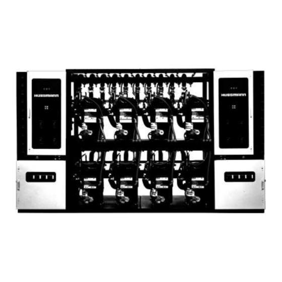
Return to Contents September 1, 1997 P/N 401789 1 - 1 INSTALLATION INSTRUCTIONS Figure 1-1 — Scroll Plus™ Fibertronic™ System OVERVIEW This section is limited to the information needed 2. Factory piping with to set the Scroll Plus™ Compressor System. a. -
Page 13: Shipping Damage
Return to Contents INSTALLATION INSTRUCTIONS September 1, 1997 1 - 2 SHIPPING DAMAGE SYSTEM WEIGHTS All equipment should be thoroughly examined for Base Rack Weight shipping damage before and while unloading. Rack or Receiver Nomenclature Weight (lbs) 22YU This equipment has been carefully inspected at 01FY our factory and the carrier has assumed responsi- 03FY... -
Page 14: Machine Room Requirements
Return to Contents September 1, 1997 P/N 401789 1 - 3 MACHINE ROOM REQUIREMENTS The equipment room floor must solidly support the Consult NEC National Fire Handbook, particu- compressor unit as a live load. Ground level instal- larly “Installation of Switch Boards” and lation seldom presents problems, but a mezzanine “Working Space Requirements”. - Page 15 Return to Contents INSTALLATION INSTRUCTIONS September 1, 1997 1 - 4 Minimum Allowable Distances Maximum Allowable Distances From a Water Cooled Condenser Outlet to the Remote Satellites should not be placed below the Scroll Plus Receiver Inlet, the minimum allow- level of the Scroll Plus Rack.
-
Page 16: Lifting And Leveling
Return to Contents September 1, 1997 P/N 401789 1 - 5 LIFTING AND LEVELING SETTING WITHOUT A CRANE Using rigging with a spreader bar, the Scroll Plus In many locations crane lifting may not be prac- System may be lifted into position. The spreader tical. - Page 17 Return to Contents September 1, 1997 P/N 401789 2 - 1 REFRIGERATION PROCESS OVERVIEW This section details the refrigeration process by In this instruction the following criteria is main- tracking the refrigerant flow through the system tained to assist the reader. components.
- Page 18 Return to Contents REFRIGERATION PROCESS September 1, 1997 2 - 2 Heat Reclaim Coil Evaporator Condenser Heat Exchanger Turba-Shed Discharge Manifold Satellite Evaporator Satellite Compressor Suction Manifold Heat Exchanger Evaporator Valve Heat Exchanger Koolgas Manifold Liquid Manifold Receiver Figure 2-1 — Scroll Plus™ Fibertronic™ Refrigeration System HUSSM ANN CORPORATION •...
- Page 19 Return to Contents September 1, 1997 P/N 401789 2 - 3 Ball Valve Check Valve High Pressure Hot Vapor Compressor Service Valve 2-Way Valve High Pressure Warm Vapor 3-Way Valve Valve Solenoids High Pressure Warm Liquid Sight Glass Reduced Pressure Warm Suction Filter Liquid...
-
Page 20: Basic Refrigeration Cycle
Return to Contents REFRIGERATION PROCESS September 1, 1997 2 - 4 A 3-way Heat Reclaim Valve (HS) directs the Evaporator refrigerant to either the condenser or a heat Heat Reclaim 3-Way Valve reclaim coil. When the HS solenoid is de-ener- Condenser gized the valve directs the refrigerant to the condenser. - Page 21 Return to Contents September 1, 1997 P/N 401789 2 - 5 The Main Liquid Pressure Differential Solenoid Valve (MS) functions during Koolgas defrost to reduce pressure to the Liquid Manifold. This valve never closes completely but restricts the liquid line, reducing the pressure in the liquid manifold, thus enabling the reverse flow of refrig- erant necessary for Koolgas Defrost.
-
Page 22: Heat Reclaim Cycle
Return to Contents REFRIGERATION PROCESS September 1, 1997 2 - 6 HEAT RECLAIM CYCLE Heat Reclaim Coil The Heat Reclaim 3-way Valve (HS), when energized, routes the superheated discharge vapor to a remote mounted coil or to a water Condenser heating coil. -
Page 23: Koolgas Defrost Cycle
Return to Contents September 1, 1997 P/N 401789 2 - 7 Refrigeration Mode Defrost Mode Evaporator Evaporator Suction Manifold Koolgas Manifold Receiver Liquid Manifold High Pressure Hot Vapor High Pressure Warm Vapor Low Pressure Cool Vapor High Pressure Warm Liquid Reduced Pressure Warm Liquid Figure 2-13 —... -
Page 24: Oil Cycle
Return to Contents REFRIGERATION PROCESS September 1, 1997 2 - 8 OIL CYCLE Discharge refrigerant carries droplets of oil from The Sporlan Traxoil is an electronic oil level reg- the compressors’ lubrication system. The Turba- ulator. The unit is powered by a 24V power sup- shed separates the oil from the refrigerant and ply. -
Page 25: Mechanical Subcooling
Return to Contents September 1, 1997 P/N 401789 2 - 9 LIQUID INJECTION OVERVIEW SUBCOOLING Autosurge for Ambient Subcooling Scroll compressors require liquid injection when applied in low temperature applications. The Autosurge Valve directs the flow of refrig- Liquid injection is only available with ZF erant either through the Receiver (Flow models. - Page 26 Return to Contents REFRIGERATION PROCESS September 1, 1997 2 - 10 Condenser Discharge Manifold Valve Turba- Shed Flooding Valve A-7 High Pressure Hot Vapor Autosurge High Pressure Warm Liquid Valve High Pressure Warm Vapor Cut Away Not Shown - Empty Receiver Figure 2-17 —...
-
Page 27: Component Piping
Return to Contents September 1, 1997 P/N 401789 3 - 1 COMPONENT PIPING OVERVIEW REFRIGERATION LINE RUNS This section deals with the information necessary Liquid lines and suction lines must be free to for installing the refrigeration lines for a Scroll expand and contract independently of each other. - Page 28 Return to Contents COMPONENT PIPING September 1, 1997 3 - 2 Through Walls or Floors P-Trap Construction Refrigeration lines run through walls or floors must A P-Trap must be installed at the bottom of all be properly insulated. Avoid running lines through suction risers to return oil to the compressors.
-
Page 29: Rack To Condenser Piping
Return to Contents September 1, 1997 P/N 401789 3 - 3 RACK TO CONDENSER PIPING WARNING Connecting to One Manifold Vent the Receiver •Discharge Line will be routed directly to the con- Safety Relief Valve denser inlet stub with a purge valve at the highest properly. - Page 30 Return to Contents COMPONENT PIPING September 1, 1997 3 - 4 Connecting to Two Manifolds •Discharge Line will be tee’d upstream of the •Liquid Return Lines will be teed into the Main manifolds into expansion offsets with at least a 1 Liquid Return Line after 6 feet of vertical drop foot drop to the manifolds.
- Page 31 Return to Contents September 1, 1997 P/N 401789 3 - 5 6-Inch 6-Inch Minimum Minimum Rise Rise 12-Inch Minimum Drop Header End Header End Store Roof of Condenser of Condenser 6-Foot* Minimum All Piping and Valves Drop before above this line From Heat From Heat Tee to...
-
Page 32: Rack To Heat Reclaim
Return to Contents COMPONENT PIPING September 1, 1997 3 - 6 Table 3-1 “L” Values for Figuring RACK TO HEAT RECLAIM Offsets and Expansion Loops Because of the variety of Heat Reclaim systems, Inches Expansion Line Size refer to the instructions accompanying the system to be installed at the site. -
Page 33: Special Piping For Open Rooms
Return to Contents September 1, 1997 P/N 401789 3 - 7 For an expansion loop, multiply the “L” value by CONNECTING PARALLEL 3-WAY 2 if hard copper and long radius elbows are used. VALVES If the the expansion loop is formed in soft copper, the loop diameter equals “L”. -
Page 34: Line Sizing
September 1, 1997 3 - 8 LINE SIZING Sizing of all refrigerant lines is the responsibility Liquid Line of the installing contractor. Refer to Hussmann TIME AND LECTRIC EFROST Refrigerant Line Sizing. •May be reduced by one size after one half the case load run. -
Page 35: Electrical
The scope of this section is limited to main field For Remote Header Defrost Assembly: wiring connections and to the control panel. To the remote defrost control panel provide Hussmann’s Scroll Plus Control Panels feature – one 120V 1PH 15A branch circuit. ™... -
Page 36: Wiring Guidelines Based On Various Components
Return to Contents ELECTRICAL September 1, 1997 4 - 2 WIRING GUIDELINES BASED ON VARIOUS COMPONENTS Check the store legend for components requiring Select Wire Size electrical circuits to either the compressor unit or Based on the serial plate ampacity of the system, the defrost control panel. -
Page 37: Using Schematics
Return to Contents September 1, 1997 P/N 401789 4 - 3 USING SCHEMATICS Fuse Power Line Remote Light Neutral Rack Opens on Alarm ALARM LIGHT Remote BSR Coil Alarm Common BELL Electronic STOP Circuit Circuit Closes on Alarm Inputs Alarm on circuit open COMP AR Coil... -
Page 38: Compressor Controls
Return to Contents ELECTRICAL September 1, 1997 4 - 4 COMPRESSOR CONTROLS Alarm Board 5 AMP Fuse Power ALARM LIGHT BELL STOP COMP HUSSMANN PUSH TO RESET RACK ALARM Fuse ALARM LIGHT BSR Coil BELL Electronic STOP Circuit COMP AR Coil... - Page 39 Return to Contents September 1, 1997 P/N 401789 4 - 5 Alarm Board Troubleshooting Check power supply to the Alarm Board and its Fuse F1. Disconnect power. Label, disconnect and cap wires on terminals COMP, A9, T9A, 33, 31, 35, 34, 36, 32. Install a fused jumper from X1 to 34 and with open switches to COMP, A9, T9A.
- Page 40 Return to Contents ELECTRICAL September 1, 1997 4 - 6 BOARD POWER COMPRESSOR ALARM SWITCH OFF TO RESET FAILURES FUSE HIGH PRESSURE OIL FAILURE Figure 4-3 Compressor Board Faceplate Figure 4-3 — Compressor Board Faceplate Compressor Circuit Board Compressor Control Circuit Switch Compressor On –...
- Page 41 Return to Contents September 1, 1997 P/N 401789 4 - 7 3 2 1 7 6 5 4 3 2 1 FUSE1 Relay AUTO ECC1 ECC2 Relay SWBK Figure 4-4 — Compressor Circuit Board Connections P2 connects to the contactor, supplying output to T3 provides power to the K2 Relay Circuit.
- Page 42 Return to Contents ELECTRICAL September 1, 1997 4 - 8 Compressor Board using Mechanical Low Pressure Control or Series Switchback 3 2 1 7 6 5 4 3 2 1 FUSE1 AUTO ECC1 ECC2 SWBK Power LED Alarm LED Fuse LED Oil LED H Press LED Circuit...
- Page 43 Return to Contents September 1, 1997 P/N 401789 4 - 9 Table 4-3 — Compressor Board Troubleshooting — Mechanical Troubleshooting—Compressor Board (Mechanical Low Pressure Control or Series Switchback) Be sure Board Switch is closed. Run, Refrigeration Mode Voltmeter Voltmeter Action Lead Placement Readings Lead 1...
- Page 44 Return to Contents ELECTRICAL September 1, 1997 4 - 10 3 2 1 7 6 5 4 3 2 1 FUSE1 AUTO ECC1 ECC2 SWBK Power LED Alarm LED Fuse LED Oil LED H Press LED Circuit Circuit Run LED Figure 4-6 —...
- Page 45 Return to Contents September 1, 1997 P/N 401789 4 - 11 Table 4-4 — Compressor Board Troubleshooting — Electronic Troubleshooting—Compressor Board (EPC Control) Be sure Board Switch is closed. Run, Refrigeration Mode Voltmeter Voltmeter Action Lead Placement Readings Lead 1 Lead 2 Go to 2 Check Power Supply to Board...
-
Page 46: Compressor Board Related Circuits
Return to Contents ELECTRICAL September 1, 1997 4 - 12 K2 Relay Coil - Circuit EPC Compressor Controller Contacts Compressor Motor Contactor Coil - Circuit Power LED Alarm LED Jumper from all Fuse LED Boards Oil LED H Press LED Circuit Circuit Jumper... - Page 47 Return to Contents September 1, 1997 P/N 401789 4 - 13 Compressor K1 Relay Coil - Circuit Tracer Controller Contacts Compressor Alarm Relay Coil - Circuit Tracer Power LED Alarm LED Jumper from all Fuse LED Oil LED Boards H Press LED Circuit Circuit K1 Alm...
- Page 48 Return to Contents ELECTRICAL September 1, 1997 4 - 14 EPC Switchback Relay X24 X2D EPC Compressor Time Delay Switchback (TDSB) Relay Controller Contacts 24 Sec Delay Compressor Board #1 Power LED 24 Sec Delay TDSB Alarm LED Fuse LED Oil LED H Press LED Circuit...
- Page 49 Return to Contents September 1, 1997 P/N 401789 4 - 15 X24 X2D Compressor Board #1 Power LED Alarm LED Electronic Compressor Controller Fuse LED Oil LED H Press LED Circuit Circuit Run LED C# Protector C# Aux Cont on Compressor Board #2 Motor Cont Coil on Compressor Board #3 Time Delay...
- Page 50 Return to Contents ELECTRICAL September 1, 1997 4 - 16 Power LED Alarm LED Fuse LED Oil LED H Press LED Circuit Circuit Run LED C# Aux Cont C# Protector Motor Cont Coil Oil Failure Low Pressure Control Sequencer Series Switchback Individual Time Delay Switchback Compressor Controls Between P1,1 and P1,2 one of three compressor...
- Page 51 Return to Contents September 1, 1997 P/N 401789 4 - 17 Power LED Alarm LED Fuse LED Oil LED H Press LED Circuit Circuit Run LED C# Aux Cont C# Protector Motor Cont Coil Oil Failure Koolgas Relay T4 on Branch Defrost Board Koolgas Relay To assure proper operation of the rack, it is...
- Page 52 Return to Contents ELECTRICAL September 1, 1997 4 - 18 Compressor Protection Compressor protection is determined by the type of compressor used. These controls are wired between P1,3 and P1,8. Since the controls reset automatically, an open compressor protector will not cause an alarm situation.
- Page 53 Return to Contents September 1, 1997 P/N 401789 4 - 19 Crankcase Heater The normally closed contacts of the Crankcase Heater Relay open when the Compressor Motor Contactor Coil is energized, so the heater is off while the compressor is running. Power LED Alarm LED Fuse LED...
-
Page 54: Defrost Circuit Boards
Return to Contents ELECTRICAL September 1, 1997 4 - 20 BRANCH ON DEFROST SOLENOID LIQUID BRANCH SOLENOID Figure 4-15 — Branch Board Faceplate DEFROST CIRCUIT BOARDS Defrost Control Circuit Switch (“ON/OFF”) EPR Solenoid – Green LED – indicates the suc- shuts off all power to the defrost branch circuit. - Page 55 Return to Contents September 1, 1997 P/N 401789 4 - 21 KOOLGAS/3W EPR SOL LIQ BRANCH Figure 4-18 Defrost Board Inputs and Outputs Figure 4-16 — Defrost Board Inputs and Outputs (View—removed from panel, faceplate held in left hand.) (View—removed from panel, faceplate held in left hand.) FUSE, 5A on circuit board can only be replaced TEMP TERM is input from defrost termination by removing board from panel.
- Page 56 Return to Contents ELECTRICAL September 1, 1997 4 - 22 KOOLGAS/3W EPR SOL LIQ BRANCH Q1 Q4 ASSY 0340132 TEMP TERMINATION P1,1 T-STAT P1,2 KOOL- FUSE 5AMP RELAY ON/OFF DEFROST BRANCH BOARD P2,1 P3,2 P3,1 P2,2 TEMP TERM Figure 4-17 — Defrost Board – Electronic Timer Figure 4-20 Defrost Board - Electronic Timer HUSSM ANN CORPORATION •...
- Page 57 Return to Contents September 1, 1997 P/N 401789 4 - 23 Table 4-4 — Troubleshooting—Defrost Board with Mechanical Time Clock Be sure Board Switch is closed. Refrigeration Mode Voltmeter Voltmeter Action Lead Placement Reading Lead 1 Lead 2 T1 (X1) T11 (X2) Go to 2 Check Power Supply to Board...
-
Page 58: Defrost Control Circuits
Return to Contents ELECTRICAL September 1, 1997 4 - 24 DEFROST CONTROL CIRCUITS The different defrost systems shown on the wiring The basic circuit is controlled by a defrost clock diagrams all work from the same basic circuit. The which closes the circuit, energizing relay coil R1. variations come from tailoring the systems to the R1 controls one contact 1R1 (normally closed) customers’... - Page 59 Return to Contents September 1, 1997 P/N 401789 4 - 25 Suction Stop Koolgas Defrost When the defrost clock energizes Defrost Relay Coil R1 Contact 1R1 will turn “OFF” the EPR Solenoid (ES) Contacts 2R1 will turn “ON” the Koolgas Solenoid (KS) and Koolgas Relay (KR) power to T4 thru Yellow wire to KR terminal...
- Page 60 Return to Contents ELECTRICAL September 1, 1997 4 - 26 Electric Defrost When the defrost clock energizes Defrost Relay Coil R1 Contact 1R1 will turn “OFF” the Liquid Line Solenoid Contact 2R1 will turn “ON” Branch Defrost Contactor in the Electric Defrost Panel power to T4 thru Orange wire to D__ terminal thru field wiring to corresponding D__ terminal in Electric Defrost Panel.
- Page 61 Return to Contents September 1, 1997 P/N 401789 4 - 27 Off Cycle Defrost When defrost clock energizes Defrost Relay Coil R1 Contact 1R1 will turn “OFF” Liquid Line Solenoid Valve (S). T-STAT P1,1 P1,2 Kool- FUSE 5AMP Relay ON/OFF Defrost Branch Board...
-
Page 62: Other Controls
5 Amp Fuse 5 Amp Fuse Field Supplied Hussmann’s EPC-2000 provides both anti-short Field Supplied cycle and stagger-start delays. During switchback operation when the EPC-2000 is not controlling the system, sensible delays, safeties and controls can maintain less efficient operation. -
Page 63: Power Monitor
Return to Contents September 1, 1997 P/N 401789 4 - 29 PVCL —400—AR UNDER VOLTAGE SUPPLY: CONTACTS 440-480V, OUTPUT 7 A, 240VAC 3Ø Single Phase Monitor Figure 4-24 — Power Monitor and Slave Contactor Figure 4-27 Power Monitor and Slave Contactor POWER MONITOR The single phase monitor detects phase loss, phase reversal, low voltage, and phase imbalance. -
Page 64: Overview
Return to Contents September 1, 1997 P/N 401789 5 - 1 REMOTE SATELLITES AND CONDENSERS OVERVIEW This section deals with standard guidelines for Shipping Damage installation of Remote Satellites and Remote Air All equipment should be thoroughly examined for Cooled Condensers. Piping is covered in shipping damage before and while unloading. -
Page 65: Lifting And Leveling
Return to Contents REMOTE SATELLITES & CONDENSERS September 1, 1997 5 - 2 Lifting and Leveling Single-tier Satellites require three straps, front and two sides supported. Two-tier Satellites are provid- ed with lifting eyes. Use a spreader bar and observe minimum rigging angle of 45Þ. -
Page 66: Remote Condensers
Return to Contents September 1, 1997 P/N 401789 5 - 3 REMOTE CONDENSERS General Description Air Cooled Application The Scroll Plus Fibertronic system is available for Split condenser valving is recommended if any of use with three types of condensers: remote air the following conditions exist: cooled, water cooled, and evaporative water 1. -
Page 67: Lifting And Leg Assembly
Return to Contents REMOTE SATELLITES & CONDENSERS September 1, 1997 5 - 4 Figure 5-2 — Lifting the Condenser Lifting and Leg Assembly Location Under no circumstances should the condenser Locate the condenser with at least six feet of manifolds, piping return bends or control panel clearance on all sides to provide adequate air be used for lifting or moving the unit. -
Page 68: Preliminary Electrical Check
Return to Contents September 1, 1997 P/N 401789 5 - 5 Route and support all piping in a manner that 2. Liquid return line: Route each liquid return relieves stress caused by vibration, thermal expan- line downward at least 6 feet between outlet sion, and gradual base or building movement. -
Page 69: Physical Data
Return to Contents REMOTE SATELLITES & CONDENSERS September 1, 1997 5 - 6 Table 5-1 — Physical Data Physical Data Weight /w Max Flood Inlet/Outlet FLA 3PH Max. Flood Charge Connections Model Fans (lbs) (lbs) R404A/ R404A/ 208V 230V 460V R507 R22 R507 HLCVB... - Page 70 Return to Contents Figure 5-3 — Ambient Control of All Banks With Pressure Override of the First Fan Bank 208/3/60 230/3/60 460/3/60 Ambient Temperature Control of All Banks With Pressure Override of the First Fan Bank 208/3/60 230/3/60 460/3/60...
- Page 71 Figure 5-4 — Pressure Control and Gravity Dampers for all Fan Banks 208/3/60 230/3/60 460/3/60 Pressure Control and Gravity Dampers for all Fan Banks 208/3/60 230/3/60 460/3/60 31 32 33 37 38 39 34 35 36 40 41 42 Return to Contents...
-
Page 72: Split Condensers
Return to Contents September 1, 1997 P/N 401789 5 - 9 SPLIT CONDENSERS Remote Condenser Header End of Condenser 6 Ft Minimum Recommended Cond From Suction Valve Suction Drain Line PTIONAL From ACTORY NSTALLED Turba-Shed PLIT ONDENSER ALVE Suction Condensate Manifold Lines Oil Separator... -
Page 73: Electrical And Preliminary Checkout
Return to Contents REMOTE SATELLITES & CONDENSERS September 1, 1997 5 - 10 ELECTRICAL AND PRELIMINARY CHECK-OUT The following electrical diagrams show the inter- 3. Check that the proper winter condensing pres- nal wiring. Consult motor serial plate for wire sure control has been applied as follows: sizes. - Page 74 Return to Contents Ambient Temperature Control of All Banks of Fans Except The One Nearest the Header for 2, 3, 4, or 5 Fan Bank Condenser Fuses and Fuse Blocks Supplied When Required TC-1 TC-2 TC-3 TC-4 Header Replacement Parts Control Settings Thermostat Control Number of...
- Page 75 Ambient Temperature Control of All Banks of Fans Except The One Nearest the Header for 2, 3, 4, or 5 Fan Bank Condenser Header TC-1 TC-2 TC-3 TC-4 Thermally Protected Motors Replacement Parts Control Settings Thermostat Control Number of Cut-In Settings for Thermostats – Deg F Thermostats TC-1 TC-2...
- Page 76 Return to Contents Ambient Temperature Control of All Banks of Fans With Pressure Override of the First Cycling Fan Bank for 2, 3, 4, or 5 Fan Bank Condenser Fuses and Fuse Blocks Supplied When Required TC-1 PC-1 TC-2 PC-2 TC-3 TC-4 TC-5...
- Page 77 Ambient Temperature Control of All Banks of Fans With Pressure Override of the First Cycling Fan Bank for 2, 3, 4, or 5 Fan Bank Condenser PC-2 PC-1 Header TC-2 TC-3 TC-4 TC-5 TC-1 TC-6 Thermally Protected Motors Replacement Parts Control Settings Thermostat Control Number of...
- Page 78 Return to Contents Line Voltage Pressure Control and Gravity Dampers for All Fans Fuses and Fuse Blocks Supplied When Required PC-1 PC-2 PC-3 PC-4 PC-5 Header Control Settings Replacement Parts Number of Fans Pressure Switch Cut-In Settings – psig Single Double Refrigerant PC-1...
- Page 79 Return to Contents Pilot Operated Pressure Control and Gravity Dampers for All Fans Fuses and Fuse Blocks Supplied When Required PC-1 PC-2 PC-3 PC-4 PC-5 Header Control Settings Replacement Parts Number of Fans Pressure Switch Cut-In Settings – psig Single Double Refrigerant PC-1...
-
Page 80: Control Valves
Return to Contents September 1, 1997 P/N 401789 6 - 1 CONTROL VALVES OVERVIEW This section deals with the operation and mainte- positive differential of at least 50 psig above the nance of the major valves which may be found down stream side of the valve. -
Page 81: Koolgas Valves
Return to Contents CONTROL VALVES September 1, 1997 6 - 2 Table 6-1 — Troubleshooting EPR Valves Malfunction Cause Action Fails to Open Dirt holding pilot port open Disassemble and clean Solenoid not energized -bad solenoid Replace solenoid -circuit open find and repair open -stuck in defrost mode correct defrost clock problem... - Page 82 Return to Contents September 1, 1997 P/N 401789 6 - 3 From Koolgas To Evaporator Manifold Figure 6-3 — 2-Way Solenoid Valve Both the EPR and the 2-way solenoid valves are normally closed, so the EPR must be powered From Koolgas Manifold only during refrigeration and the 2-way valve only during defrost.
-
Page 83: Main Liquid Line Solenoid Valves
Return to Contents CONTROL VALVES September 1, 1997 6 - 4 MAIN LIQUID LINE SOLENOID VALVES Differential Mode Quick Test The Sporlan Main Liquid Line Solenoid Valve goes 1. Connect pressure gauges up- and downstream into differential mode when the coil is de-energized of the valve. - Page 84 Return to Contents September 1, 1997 P/N 401789 6 - 5 The Alco Main Liquid Line Solenoid Valve goes into differential mode when the coil is de-energized or fails. Upstream liquid is forced through the modulating valve when the upstream pressure exceeds downstream pressure plus the spring pressure...
-
Page 85: Branch Liquid Line Solenoid Valves
Return to Contents CONTROL VALVES September 1, 1997 6 - 6 BRANCH LIQUID LINE Valve Port SOLENOID VALVES Upstream Equalizing Port The Branch Liquid Line Solenoid Valve closes off refrigerant supply to the evaporator, yet allows back flow of refrigerant into the Liquid Manifold for Koolgas Defrost. -
Page 86: Tev
Return to Contents September 1, 1997 P/N 401789 6 - 7 The Thermal Expansion Valve regulates refriger- Diaphragm ant flow into the evaporator by responding to the temperature of superheated vapor at the outlet of Equalizer the evaporator. Port Inlet Before attempting to set a TEV be sure the mer- Outlet chandiser is within 10ÞF of its normal operating... - Page 87 Return to Contents CONTROL VALVES September 1, 1997 6 - 8 Table 6-4 — Troubleshooting the TEV Malfunction Cause Action Evaporator Superheat adjusted Adjust to proper superheat Starved too high Moisture Dehydrate and install new liquid line filter dryer Dirt plugging strainer Remove and clean or replace or valve mechanism Clean valve and install wax trapping dryer...
-
Page 88: Heat Reclaim
Return to Contents September 1, 1997 P/N 401789 6 - 9 HEAT RECLAIM De-energized A 3-Way Heat Reclaim Valve directs the refrigerant to either the Condenser or a Heat Reclaim Coil. When the solenoid is de-energized, the valve directs the To Suction Manifold refrigerant to the condenser. -
Page 89: Flooding Valve And Receiver Pressure Regulating Valve
Return to Contents CONTROL VALVES September 1, 1997 6 - 10 Condenser FLOODING VALVE AND RECEIVER PRESSURE REGULATING VALVE The Flooding Valve and the Receiver Pressure Turba- Shed Regulating Valve work together—the operation of Discharge Manifold one affects the operation of the other. The Flooding Valve responds to upstream pressure from the Condenser. - Page 90 Return to Contents September 1, 1997 P/N 401789 6 - 11 A9 Valve Operation Downstream Pressure must be sufficient to keep Adjustment Spring from opening Valve Port . If receiver pressure falls below the spring set point, the valve port opens, allowing Upstream Pressure to fill the Valve Chamber , opening the Main Valve...
-
Page 91: Autosurge And By-Pass Valves
Return to Contents CONTROL VALVES September 1, 1997 6 - 12 AUTOSURGE AND BY-PASS VALVES The A9B Valve needs to be working properly The Autosurge Valve reacts to the condensing for the Autosurge Valve to function during pressure through its equalizer line, and to the Koolgas Defrost. - Page 92 Return to Contents September 1, 1997 P/N 401789 6 - 13 System Start-up Emergency Bypass The pilot valve is pre-set at the factory for 10 If the pilot valve fails for any reason, the system subcooling. will be forced into Surge flow around the Receiver.
- Page 93 Return to Contents CONTROL VALVES September 1, 1997 6 - 14 Testing Valve Operation Main Valve To test the Main Valve, isolate the Pilot Valve and General When taking readings, account for liquid line connect the Autosurge Schrader Valve to the cen- drop, gauge error, and thermometer accuracy.
-
Page 94: Mechanical Subcooling
Return to Contents September 1, 1997 P/N 401789 6 - 15 MECHANICAL SUBCOOLING By lowering the temperature of the liquid A liquid line solenoid valve and a TEV control supplied to the TEV, the efficiency of the evapora- refrigerant flow to the Plate Heat Exchanger. An tor is increased. -
Page 95: Oil Cycle
Return to Contents CONTROL VALVES September 1, 1997 6 - 16 OIL CYCLE Discharge refrigerant carries droplets of oil from The Sporlan Traxoil is an electronic oil level the compressors’ lubrication system. The regulator. The unit is powered by a 24V power Turbashed separates the oil from the refrigerant supply. -
Page 96: Control Settings
Return to Contents September 1, 1997 P/N 401789 7 - 1 CONTROL SETTINGS OVERVIEW PLATE SUBCOOLING CONTROLS This section is limited to the control settings Thermostat setting is 50 deg F, with minimum dif- required prior to and during start-up. These ferential, or customer specification. -
Page 97: Winter Condensing Pressure Controls
Return to Contents CONTROL SETTINGS September 1, 1997 7 - 2 WINTER CONDENSING PRESSURE MECHANICAL LOW PRESSURE CONTROLS CONTROLS The customer may specify lower pressure settings The Alco low pressure control comes with a fac- than those recommended; however, refrigeration tory set cut-in pressure of 15 psig. - Page 98 Return to Contents September 1, 1997 P/N 401789 7 - 3 Alco Cartridge-style Low Pressure Control Cut Out Pressures Apply data from compressors 1 and 2 for a 2-compressor rack; data from compressors 1 through 3 for a 3-compressor rack; and so on. R-404A/R507 Design Compressor Capacity...
- Page 99 Return to Contents CONTROL SETTINGS September 1, 1997 7 - 4 Other Mechanical Low Pressure Control Settings R-404A/R507 Low Temperature Compressor Compressor Compressor Compressor Compressor Compressor Design Number 6 Number 5 Number 4 Number 3 Number 2 Number 1 Suction Temp ÞF psig...
- Page 100 Return to Contents September 1, 1997 P/N 401789 7 - 5 R-404A Medium Temperature Compressor Compressor Compressor Compressor Compressor Compressor Design Number 6 Number 5 Number 4 Number 3 Number 2 Number 1 Suction Temp ÞF psig psig psig psig psig psig psig...
- Page 101 Return to Contents CONTROL SETTINGS September 1, 1997 7 - 6 R22 Medium Temperature Compressor Compressor Compressor Compressor Compressor Compressor Design Number 6 Number 5 Number 4 Number 3 Number 2 Number 1 Suction Temp ÞF psig psig psig psig psig psig psig...
- Page 102 Return to Contents September 1, 1997 P/N 401789 7 - 7 R22 Low Temperature Compressor Compressor Compressor Compressor Compressor Compressor Design Number 6 Number 5 Number 4 Number 3 Number 2 Number 1 Suction Temp psig psig psig psig psig psig psig psig...
-
Page 103: Condenser Pressure And Temperature Settings
CONDENSER PRESSURE AND TEMPERATURE SETTINGS HLCVB, HLVCF, HLCVG, HLCVI, HLVCV, HLCVW Refrigerants 404A/507 & 22 Condenser Pressure Settings psig Ambient Control Split Cond Heat Reclaim Heat Reclaim PC1 PC2 PC3 PC4 PC5 PC6 PC7 Pressure psig Temperature ÞF Thermostat Pressure Lockout Alignment PC2 TC1 TC2 TC3 TC4 TC5 TC6 TC7 SettingÞF... -
Page 104: Merchandiser Settings
Return to Contents September 1, 1997 P/N 401789 7 - 9 MERCHANDISER SETTINGS Application MEAT M3GE Models M1GE M2GE M5GE Refrigeration Discharge Air Temperature ÞF 27°F 28°F 27°F 28°F 26°F 26°F 29°F 28°F 28°F Evaporator TemperatureÞF 18°F 21°F 18°F 21°F 18°F 21°F 21°F... - Page 105 Return to Contents CONTROL SETTINGS September 1, 1997 7 - 10 MERCHANDISER SETTINGS (Cont'd) Application PRODUCE Models (End) (End) Refrigeration Discharge Air Temperature ÞF 29°F 31°F 34ÞF 34ÞF 32ÞF 32ÞF Evaporator TemperatureÞF 21°F 24°F 21ÞF 24ÞF 21ÞF 24ÞF Fan Cycling CI/CO ÞF —...
- Page 106 Return to Contents September 1, 1997 P/N 401789 7 - 11 MERCHANDISER SETTINGS (Cont'd) Application MEAT, DELI, DAIRY, P & P DAIRY / DELICATESSEN Models C2LE C2XLE D5LE D5GE C2XE D5NHE C2LGE C2XLGE D5HE D5NGE D6LE D5LR D5LRE D5HR D5RE D5HRE D5NLE D5NE...
- Page 107 Return to Contents CONTROL SETTINGS September 1, 1997 7 - 12 MERCHANDISER SETTINGS (Cont'd) Application DAIRY DELICATESSEN FROZEN FOOD ICE CREAM Models Refrigeration Discharge Air Temperature ÞF 34ÞF 30ÞF –5ÞF –12ÞF Evaporator TemperatureÞF 27ÞF 23ÞF –11ÞF –19ÞF Fan Cycling CI/CO ÞF —...
- Page 108 Return to Contents September 1, 1997 P/N 401789 7 - 13 MERCHANDISER SETTINGS (Cont'd) Application FROZEN FOOD ICE CREAM Models LWUG LWUG LWEG LWEG Refrigeration Discharge Air Temperature ÞF –12ÞF –10ÞF –12ÞF –22ÞF –20ÞF –20ÞF Evaporator TemperatureÞF –20ÞF –20ÞF –20ÞF –30ÞF –30ÞF –30ÞF...
- Page 109 Return to Contents CONTROL SETTINGS September 1, 1997 7 - 14 MERCHANDISER SETTINGS (Cont'd) Application ICE CREAM FROZEN FOOD MEAT Models NEBSHM G5CH FMLG G5FL G5FH For all Merchandisers G6CH with Gravity Coils, the GWIC NRCV G6FL NRFV Temperature listed in GWIT GWIT G6FH...
- Page 110 Return to Contents September 1, 1997 P/N 401789 7 - 15 MERCHANDISER SETTINGS (Cont'd) Application MEAT DELI Models CGDM CGDM CGDMG CSDM CSDM FHMG FMRV CGDMGT MWI6 FHMH FMRG CSDMG For all Merchandisers VGLR FHMGH FMGV FMRGV GWIT with Gravity Coils, the FHMS FMGC FMRGC...
- Page 111 Return to Contents CONTROL SETTINGS September 1, 1997 7 - 16 MERCHANDISER SETTINGS (Cont'd) Application DELI and CHEESE Models CGDMG CWI6 DMDH FHMG RDMH RMFA CGDMGT DMDA FHMH CSDMG For all Merchandisers VGLR MWI6 FHMGH FMGV with Gravity Coils, the FHMS FMGC VGSR...
- Page 112 Return to Contents September 1, 1997 P/N 401789 7 - 17 MERCHANDISER SETTINGS (Cont'd) Application DAIRY PRODUCE BAKERY FLORAL Models PVWI CGBR JVMR RMFA Bulk Pack DMZA JVMRS RMFA DMZH PHSM PHSM PWIRO For all Merchandisers EPWI with Gravity Coils, the DMXA PHRO PHRO...
- Page 113 Return to Contents CONTROL SETTINGS September 1, 1997 7 - 18 MERCHANDISER SETTINGS (Cont'd) Application Fresh Fish/Seafood Additional Merchandisers Models CGFM CGFMG Meat Cheese Produce CSFM CSFMG DSRP DSRP DSRP DSRP-Y For all Merchandisers with Gravity Coils, the Temperature listed in the "Discharge Air"...
- Page 114 Return to Contents September 1, 1997 P/N 401789 7 - 19 MERCHANDISER SETTINGS (Concluded) Application Walk-in and Prep Room Data Low Temp Coolers Medium Temp Coolers Models Ice Cream Frozen Food Meat Dairy Produce Prep Areas Deli Beverage For all Merchandisers with Gravity Coils, the Temperature listed in the "Discharge Air"...
-
Page 115: Start-Up And Maintenance
Return to Contents September 1, 1997 P/N 401789 8 - 1 START-UP AND MAINTENANCE Warning Know whether a circuit is open at the power supply or not. Remove all power before opening control panels. Note: Some equipment has more than one power supply. Always use a pressure regulator with a nitrogen tank. -
Page 116: Oil Levels
Return to Contents START-UP AND MAINTENANCE September 1, 1997 8 - 2 Oil Levels Check oil levels for each compressor and the Procedure Turba-shed: Pull a vacuum to 1500 microns. If the vacuum Compressor sight glass ¼ ¼ full fails to hold, determine the cause and correct. Turba-shed between two lower sight glasses. -
Page 117: Charging
Return to Contents September 1, 1997 P/N 401789 8 - 3 Pre-charge Check List Warning Preparation for charging can begin while the sys- tem is being evacuated. During any of the pull Never trap liquid refrigerant downs, check: between closed valves. Hydraulic explosion Merchandisers may result. -
Page 118: Compressor Motor Rotation
Return to Contents START-UP AND MAINTENANCE September 1, 1997 8 - 4 Close the Ball Valve immediately downstream of Shut off all compressors and recheck oil levels in the Receiver and connect the proper refrigerant to each compressor and the Turba-shed. Leak its Access Port. -
Page 119: Final Checks
Return to Contents September 1, 1997 P/N 401789 8 - 5 Final Checks MAINTENANCE Once the system is up and running, it is the responsibility of the installer to see that all the Compressor Replacement fine adjustments are made so the Scroll Plus™ Since each machine room tends to be unique, plan Fibertronic™... -
Page 120: Cleaning The Turba-Shed
Return to Contents START-UP AND MAINTENANCE September 1, 1997 8 - 6 Plug holes to compressor manufacturer's Cleaning the Turba-shed™ specifications. Should the Turba-shed require cleaning, first shut down the system. Isolate the Turba-shed and Remove suction and discharge rotolocks. bleed off pressure into an approved recovery vessel. - Page 121 • For payment of labor for any removal or installation of warranted parts; • For any repair or replacements made without the written consent of Hussmann, or when the equipment is installed or operated in a manner contrary to the printed instructions covering installation and service which accompanied such equipment;...
Need help?
Do you have a question about the Scroll Plus Fibertronic 401789 and is the answer not in the manual?
Questions and answers