Table of Contents
Advertisement
Quick Links
Advertisement
Table of Contents

Related Manuals for KMS IB/IA23


Summary of Contents for KMS IB/IA23
-
Page 2: Table Of Contents
Contents KMS (Kronenburg Management System) ..........3 Software installation ..............4 KMS software ................5 The ignition characteristic diagram ..........5 The function bar ..............6 3.2.1 Function key F1 ..............6 3.2.2 Function key F2 ..............6 3.2.3 Function key F3 ..............6 3.2.4 Function key F4 ..............6 3.2.4.1... -
Page 3: Kms (Kronenburg Management System)
1 KMS (Kronenburg Management System) This management system can be used as an independent ignition system for virtually all types of Otto engine (engines in which the fuel mix is ignited via a spark plug). This system provides the opportunity to give the desired spark timing at any running condition, in order to achieve maximum torque and fuel efficiency at any rpm and load. -
Page 4: Software Installation
2 Software installation The software is supplied together with the system, on a CD-ROM. Installing the software is very simple. The CD-ROM carries the KMS installation program, which launches automatically when the CD is inserted. Once installed, the program is set to work via communication port COM1. If this port is already being used or not available, another communication port can be used. -
Page 5: Kms Software
In the ignition spreadsheet, figures can be entered that indicate the ignition advance angle in degrees of crankshaft rotation. This means that for any engine speed and engine load, the desired ignition moment can be entered. KMS IB/IA23 manual Version 3.01... -
Page 6: The Function Bar
The names of these files automatically receive the extension .i03 3.2.4 Function key F4 When this function key is activated, a menu will appear on the screen, which gives the option of several settings. The options will be explained in the following sections. KMS IB/IA23 manual Version 3.01... -
Page 7: Rpm Pickup
Dis coil: The choice is between dis coil and single coil control (rotor and distributor cap). Ticking the box selects dis coil mode. KMS IB/IA23 manual Version 3.01... -
Page 8: Rpm Limiters And Powershift
This minimises the duration of gear-changing. The duration of the interruption can be set to a maximum of 200 milliseconds. Depending on the type of switch, the 'NC' box should be ticked. KMS IB/IA23 manual Version 3.01... -
Page 9: Engine-Load Sensor
Tip: make the minimum value 15 and the maximum value 250. KMS IB/IA23 manual Version 3.01... -
Page 10: Shift-Light
(up to 15 watts) or via a relay. 3.2.4.5 Warning message In this option menu you can select the warning messages the ECU software must give when the connections are short-circuit. KMS IB/IA23 manual Version 3.01... -
Page 11: Remarks
1 and 8. If this number exceeds 8, sometimes the convertor will not function properly. At the advanced settings of the COM port you can change the port number of your convertor to a number between 1 and 8). KMS IB/IA23 manual Version 3.01... -
Page 12: Function Key F6
. Once again, if UNLOCKED is not clicked after the program has been changed, the changes in the system will be lost when the power supply to the system is broken KMS IB/IA23 manual Version 3.01... -
Page 13: Function Key F10
(as in the PC the modified data will not get lost when the power supply to the system is broken). This is of course only necessary if the data has not been saved to the system. KMS IB/IA23 manual Version 3.01... -
Page 14: The Communication Bar
The following readings will be shown: - Engine speed - Advanced ignition angle - Engine load These readings can be used to check whether the right sensors are being used and all settings are correct. KMS IB/IA23 manual Version 3.01... -
Page 15: Programming
(matching the current situation of the engine), even when this value is at another engine speed or engine load. To go to another engine speed or engine load, use the Page Up / Page Down keys. KMS IB/IA23 manual Version 3.01... -
Page 16: Hardware Installation
It is important that the ECU should be fitted in a dry and not too hot place. 5.2 Connecting the communication cable Attached to the included wiring loom of your KMS IB/IA23 system is a serial port. You can use this communication for you desktop/laptop and make a connection with the KMS Ignition software. -
Page 17: Fault Tracing
- Interruption in potentiometer signal wiring or potentiometer does not turn when the throttle valve is opened Only coils 1-4 give ignition - Dis coil box not ticked - See paragraph 3.2.4.1. KMS IB/IA23 manual Version 3.01... -
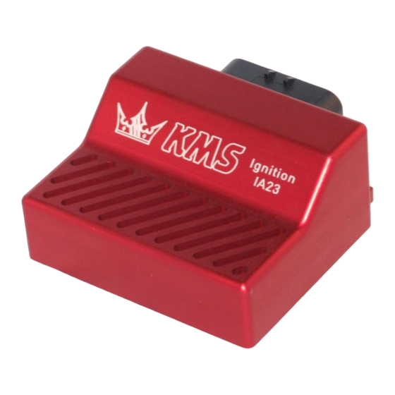
Page 18: Specifications
Shift-lamp output max. 1 amp at 12 volts per output Dimensions: KMS IA23 LxWxH: 85 x 85 x 40 mm Weight: 280 gram KMS IB LxWxH: 111 x 67 x 22 mm Weight: 200 gram KMS IB/IA23 manual Version 3.01... -
Page 19: Wiring Diagrams
8 Wiring Diagrams standard colors KMS IA23 wiring-loom PIN nr. color 0,5mm² 0,75mm² function details purple Coil 3 (amplified) For use directly on -coil purple Coil 3 Only used to trigger an coil driver red/black Tacho output Low voltage RPM signal... - Page 20 KMS IB breakout-loom color 0,5mm² 0,75mm² function details white/red Analog aux input Not yet available red/black Tacho output Low voltage RPM signal purple Coil 3 Only used to trigger an coil driver green Coil 2 Only used to trigger an coil driver...
-
Page 21: Wiring Examples
9 Wiring examples KMS IB/IA23 manual Version 3.01... - Page 22 KMS IB/IA23 manual Version 3.01...
- Page 23 KMS IB/IA23 manual Version 3.01...
- Page 24 KMS IB/IA23 manual Version 3.01...
- Page 25 KMS IB/IA23 manual Version 3.01...
Need help?
Do you have a question about the IB/IA23 and is the answer not in the manual?
Questions and answers