Table of Contents
Advertisement
Quick Links
P a g e
| 1
PRODUCT MODEL NUMBER:
TL-9542B
MPEG2/MPEG4 HD 4 in 1 Encoder Modulator
4* CVBS/HDMI/YPbPr/CC
DVB-C/DVB-T/ISDB-T/ATSC RF
MPEG2 HD & MPEG4 AVC/H.264 HD Encoding
ABOUT THIS
MANUAL
DISCLAIMER
No part of this document may be reproduced in any form without the written permission of the copyright
owner.
The contents of this document are subject to revision without notice due to continued progress in
methodology, design and manufacturing. TRANSLITE GLOBAL LLC shall have no liability for any error or
damage of any kind resulting from the use of this document.
COPY WARNING
This document includes some confidential information. Its usage is limited to the owners of the
product that it is relevant to. It cannot be copied, modified, or translated in another language
without prior written authorization from TRANSLITE GLOBAL LLC
Advertisement
Table of Contents

Related Manuals for TransLite TL-9542B

Summary of Contents for TransLite TL-9542B
- Page 1 The contents of this document are subject to revision without notice due to continued progress in methodology, design and manufacturing. TRANSLITE GLOBAL LLC shall have no liability for any error or damage of any kind resulting from the use of this document.
-
Page 2: Table Of Contents
P a g e INDEX TABLE OF CONTENTS CHAPTER 1 INTRODUCTION ........................3 1.1 PRODUCT OVERVIEW........................3 1.2 KEY FEATURES........................... 3 1.3 SPECIFICATIONS ..........................4 1.4 PRINCIPLE CHART ..........................7 1.5 APPEARANCE AND DESCRIPTION ...................... 8 CHAPTER 2 INSTALLATION ........................9 2.1 GENERAL PRECAUTIONS ........................ -
Page 3: Chapter 1 Introduction
(MPEG-2, MPEG-4/AVC H.264) and modulation to convert HDMI/YPbPr/CVBS signals etc to digital RF output. To meet customers’ various requirements, TL-9542B is also equipped with 1 ASI input, and output with 2 ASI ports and 1 IP port. The signals source could be from satellite receivers, closed-circuit television cameras, Blue-ray players, and antenna etc. -
Page 4: Specifications
P a g e ➢ LCN (Logical Channel Number) support ➢ Excellent modulation quality ➢ LCD display, Remote control and firmware ➢ Web-based NMS management; Updates via web SPECIFICATIONS Encoding Section - Video Encoding MPEG2; MPEG4 AVC/H.264 Interface HDMI*4 1920*1080_60P, 1920*1080_50P (For MPEG 4 AVC/H.264 only), Resolution 1920*1080_60i, 1920*1080_50i,... - Page 5 P a g e Audio(L/R) Encoding MPEG1 Layer II; MPEG2-AAC; MPEG4-AAC; DD AC3 (2.0) Optional Interface 1*Stereo/2*mono/1*SPDIF per channel Sample rate 48KHz 64/96/128/ 192/256/320kbps Bit rate Modulator Section – DVB-T (option) Standard EN300744 FFT mode 2K, 8K Bandwidth 6M, 7M, 8M Constellation QPSK, 16QAM, 64QAM Guard Interval...
- Page 6 P a g e ISDB-T option Standard ARIB STD-B31 Constellation DQPSK,QPSK, 16QAM, 64QAM Guard Interval 1/32, 1/16, 1/8, 1/4 Transmission Mode 2K, 4K, 8K Guard Interval 1/32, 1/16, 1/8, 1/4 Code rate 1/2, 3/4, 5/6, 7/8 RF frequency 30~999MHz, 1KHz step ATSC Standard ATSC A/53...
-
Page 7: Principle Chart
P a g e PRINCIPLE CHART... -
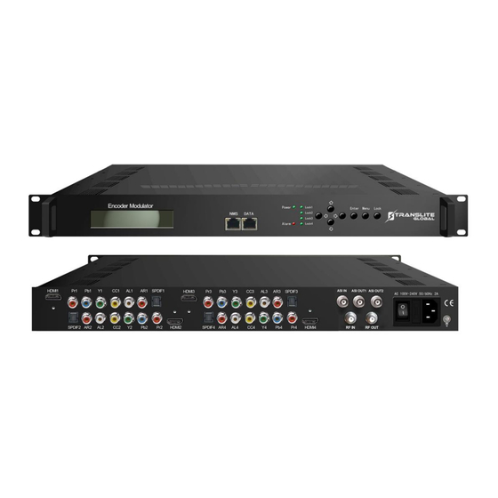
Page 8: Appearance And Description
P a g e APPEARANCE AND DESCRIPTION Front Panel Illustration 6 7 8 9 LCD Screen NMS Port Data Port Power and Alarm Indicators TS Lock Indicators Up and Down, Left and Right Buttons Enter Mode: For Confirm Menu Button: For Back Step Lock Button: Press to Lock Set Rear Panel Illustration... -
Page 9: Installation
P a g e HDMI input port YPbPr/CVBS(Pr) input port CVBS input port for CC only L/R Audio input (Stereo or mono) SPDIF Audio input port ASI Input port ASI Output port 1&2 Power switch Power supply slot port port Grounding CHAPTER 2 INSTALLATION GUIDE... -
Page 10: Power Precautions
P a g e | 10 POWER PRECAUTIONS ➢ When you connect the power source, make sure if it may cause overload. ➢ Avoid operating on a wet floor in the open. Make sure the extension cable is in good condition ➢... -
Page 11: Grounding Requirement
The area of the conduction between grounding wire and device’s frame should be no less than 25mm CHAPTER 3 OPERATION The front panel of TL-9542B Encoder Modulator is the user-operating interface and the equipment can be conveniently operated and managed by user according to the procedures displayed on the LCD:... -
Page 12: Lcd Menu Structure
P a g e | 12 Keyboard Function Description: MENU: Cancel current entered value, resume previous setting; Return to previous menu. ENTER: Activate the parameters which need modifications or confirm the change after modification. LEFT/RIGHT: Choose and set the parameters. UP/DOWN: Modify activated parameter or paging up/down when parameter is inactivated. - Page 13 P a g e | 13 3.1 Output A 3.1.1 RF On 3 Modulator 3.1.2 Standard 3.1.3 Constellation 3.1.4 Symbol Rate 3.1.5 RF Frequency 3.1.6 RF Level 3.1.7 ASI output 3.2 Output B 3.2.1-3.2.7 3.3 Output C (Same content with 3.1.1-3.1.7) 3.3.1-3.3.7 3.4 Output D 3.4.1-3.4.7...
-
Page 14: General Settings For Main Menu
P a g e | 14 Initial Status After powering on the device,it will take a few seconds to initialize the system It shows as below: DVB-C A XXX.00MHz Start OK… Start up… P1 X.XXMbps P2 X.XXMbps • DVB-C: to indicate the modulation standard of this device. •... - Page 15 P a g e | 15 Press Enter to enter “Status” and it displays the working time duration of the device. It times upon power on Uptime 1.1 Uptime 2 Days-10:30:20 2) Input Sets Under this submenu, the LCD will show “2.1 Input 1”, “2.2 Input 2” and “2.3 Input 3”. 2.1 Input 1 2.3 Input 3 2.2 Input 2...
- Page 16 P a g e | 16 “Interface”: Connect the signal source to the corresponding input channel and select the interface from the options provided in the submenu (YPbPr, CVBS and HDMI optional). Press Enter key to confirm and the system will automatically search the signal source. “Video Format”: the encoding module supports both MPEG2 and MPEG4 AVC/H.264 formats.
- Page 17 P a g e | 17 Program Output Program Name Service Provider Video Program ID Audio PMT PID Program Info PCR PID Video PID Audio PID “2.3 Input 3” represents the ASI input. User could parse and select program(s) to mux out. 2.3 Input 3 Parse Program Get 3 programs...
- Page 18 P a g e | 18 3) Modulator Setting When entering “Modulator” submenu, user can configure the modulating parameters for the 4 carrier output separately: 3.1 Output A 3.3 Output C 3.2 Output B 3.4 Output D As the TL9542B (ATSC Modulating) is with 4 carrier outputs, “3.1”-“3.4” represent the “Carrier A”, “Carrier B”, “Carrier C”, and “Carrier D”...
- Page 19 RF Level -10.0 dbm ➢ ASI Output: TL-9542B encoder & modulator (DVB-C Modulating) is with quad-carrier output A, B, C, D and 1 ASI output E. Output A: the ASI output programs are same as carrier output A. Output B: the ASI output programs are same as carrier output B.
- Page 20 P a g e | 20 : The setting principle of “3.2”, “3.3”, and “3.4” are the same with “3.1” explained above. NOTE 4) TS Config Enter each menu to configure the TS ID and Original Network ID for the 4 carriers and ASI output.
- Page 21 P a g e | 21 5.2.5Output MPTS Data Enable Null PKT Filter Output IP Output Port Service IP Subnet Mask Gateway 6) System Protocol It contains 5 submenus where users can save/load configurations. 6.1 Save Config 6.3 Factory Reset 6.2 Load Saved CFG 6.4 LCD time-out 6.5 Version...
-
Page 22: Web Nms Operation
User not only can use front buttons for setting configuration, but also can control and set the configuration in computer by connecting the device to web NMS Port. User should ensure that the computer’s IP address is different from the TL-9542B’s IP address; otherwise, it would cause IP conflict. -
Page 23: Operation
P a g e | 23 Figure-1 OPERATION Welcome When we confirm the login, it displays the WELCOME interface as shown in Figure-2. Please refer to the next page. - Page 24 P a g e | 24 Device standard and name It displays the signal source interface as per you set in “Input 1/2” interface and displays real- time encoding bit rate of corresponding input channel. User can click any item here to enter the corresponding interface to check information or...
- Page 25 P a g e | 25 Program 1 Program 2 General Settings for the input programs: User can edit any item listed as needed. Video Status: Green light indicates the corresponding source cables are properly connected. Encoding Status—Green light indicates the encoding process is running normally, which otherwise turn to red.
- Page 26 P a g e | 26 …..……………………………………..NOTE ……..……..………………………………. The different combination of Video Format, Video Bit-rate, Low delay Mode and the Resolution of signal source will have an impact on the latency. Please refer to the Chapter 6 attached for detailed information. ……………………………………………………………………………………………………..……...
- Page 27 P a g e | 27 If this item is selected, all the input programs will pass through without any elimination. Selecting this item to allow user select programs as required to output. Click “Refresh Input” to refresh the input program list. Click “Refresh Output”...
- Page 28 P a g e | 28 Click “Add” to add more boxes for filling the Input & Output PIDs, then click “Apply” to confirm. VCT (Virtual Channel Table) setting Click “VCT” from the menu to trigger the screen as Figure-5. Then click “Add” from this screen to add the program descriptor in VCT Table.
- Page 29 P a g e | 29 Figure-6 Here by clicking “Add”, users can set the program LCN in its respective field. After setting all the data, users need to click on “Save” to save the setting. Select the carrier output channel for the inserted VCT. Click “Add”...
- Page 30 P a g e | 30 This device is with MPTS IP output. The 4 boxes represent respectively IP Channel 1/2/3/4. Click the related box(es) to enable the To configure the corresponding channel(s) to output IP address and output programs. ports for the 4 IP Channels respectively.
- Page 31 P a g e | 31 To choose ASI output programs. Figure-11 Save/Restore Clicking “Save/Restore” from the menu, it will display the screen as Figure-12 where can save the configuration permanently to the device. Click “Save Configuration”, for store the data permanently to the device.
- Page 32 P a g e | 32 Restart the Device Click “Reboot” from the menu, the screen will display as Figure-13. Here when clicking “Reboot” box, it will restart the device automatically. Figure-13 Update the Device Click “Firmware” from the menu it will display the screen as Figure-14. Here user can update the device by using the update file.
- Page 33 P a g e | 33 Network When user clicks “Network”, it will display the screen as Figure-15. It displays the network information of the device. Here user can change the device network configuration as needed. Figure-15 Change Password When user clicks “Password”, it will display the password screen as Figure-16. Here user can change the Username and Password for login to the device.
- Page 34 P a g e | 34 ➢ Keyboard and LCD Lock: If it is marked with “√”,the LCD and keyboard will be locked to avoid unexpected modification or view of the device information and configurations. User can’t operate the keyboard & LCD while only the device IP address can be noted in the LCD window IP Address 192.168.000.136...
-
Page 35: Operation Of Closed Caption (Cc)
P a g e | 35 CHAPTER 5 OPERATION OF CLOSED CAPTION (CC) Closed Caption, hereinafter referred to as the CC. CC is from CVBS source output from IRD or STB etc. Connecting the CVBS cable to the CC port at the rear panel (as shown in below image), CC can be mixed with A/V inputs to generate programs with CC. -
Page 36: Low Delay Settings
CHAPTER 6 LOW DELAY SETTING TL-9542B can achieve a signal low delay from encoding to STB decoding side. User can enable the low delay function in the web-server NMS interface as shown below: Click ‘Input 1’ or ‘Input 2’ to sent a low delay mode for each program:... - Page 37 P a g e | 37 Mode 1/Mode 2: to activate the low delay function. The delay duration is based on the different combination of Video Format, Video Bit-rate, Low delay Mode and the Resolution of signal source, which combine together to have a comprehensive impact on the delay.
-
Page 38: Chapter 7 Troubleshooting
CHAPTER 7 TROUBLESHOOTING All TRANSLITE products have been passed the testing and inspection before shipping out from factory. The testing and inspection scheme already covers all the Optical, Electronic and Mechanical criteria which have been published by TRANSLITE. To prevent potential hazard, please strictly follow the operation conditions. -
Page 39: Chapter 8 Packing List
P a g e | 39 CHAPTER 8 PACKING LIST TL-9542B Encoder Modulator User's Manual HDMI Cables 2PCS YPbPr Cables 2PCS CVBS Cables 2PCS Power Cord...
Need help?
Do you have a question about the TL-9542B and is the answer not in the manual?
Questions and answers