
Related Manuals for Alpine MRV-F345


Summary of Contents for Alpine MRV-F345
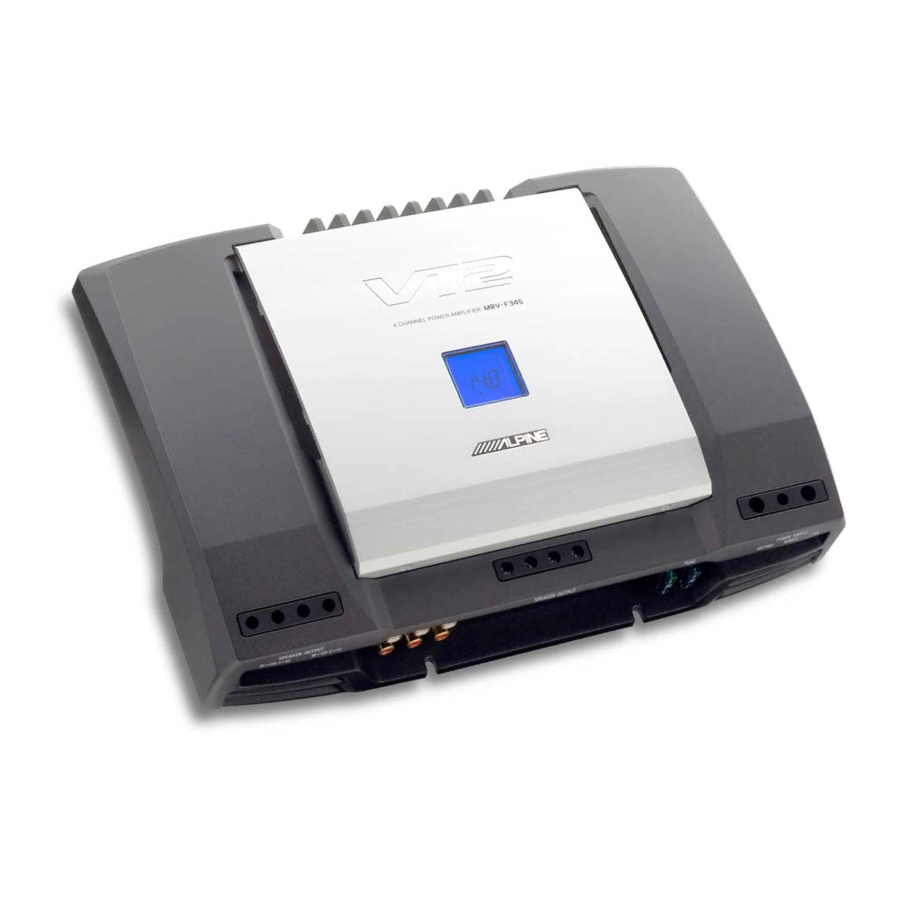
- Page 1 SERVICE MANUAL 4 CHANNEL POWER AMPLIFIER "Schematic Diagram cannot use a reference function" TO ALPINE Home Page 1 / 05-A 68E37844S01 MRV-F345...
- Page 2 <Cautions for Safe Repair Work> The following cautions will prevent accidents in the workplace and will ensure safe products. *The symbols indicate caution is needed to prevent injuries and damage to property. The symbols and their meanings follow. If you ignore this symbol and handle the product incorrectly or unsafely, Warning serious injury or death may result.
- Page 3 MRV-F345 Contents Packing Assembly Parts List Packing Method View Specifications Extension Cable Block Diagram Parts Layout on P.W.Boards and Wiring Diagram 8 to 10 Schematic Diagram 11 to 17 Terminal Voltage of IC/TR 18 to 21 Description of IC Terminal...
-
Page 4: Packing Assembly Parts List
MRV-F345 Packing Assembly Parts List Symbol Description Symbol Description Part No. Part No. 101-1 03E38301S01 SCR,M4X20 BLK 101-2 03E38302S01 WRENCH,M2.5 101-3 03E38303S01 WRENCH,M4 #1 102 68-02278Z39 OWNER'S MANUAL $1 102 68-02278Z40 OWNER'S MANUAL $1 102 68-02278Z41 OWNER'S MANUAL NOTE:#1:For North American Model Only,$1:For General Foreign Model Only,Others:Common. -
Page 5: Specifications
MRV-F345 Specifications Power Output ................4ohm x 4ch, 0.3% T.H.D.+N, 20Hz to 20kHz : 75W ch 3/4 : 2ohm & 2ohm, 0.8% T.H.D.+N, 20Hz to 20kHz : 150W ch 3/4 : 4ohm-BTL, 0.8% T.H.D.+N, 20Hz to 20kHz : 300W T.H.D....................4ohm x 4ch, 75W Power, 20Hz to 20kHz : 0.08% ch 3/4 : 2ohm &... - Page 6 MRV-F345 Extension Cable *Always connect the Extension Cable when making checks of voltage and repair. VR1 P.W.Board VR2 P.W.Board CN520 CN540 MAIN P.W.Board CN501 CN502 CN702 (1) No Extension * (2) No Extension * (3) 01E37824S01 CN602 * It is possible to use by existing cable in product.
- Page 7 MRV-F345 Block Diagram SPEAKER TERMINAL FLAT ch1 POWER AMP MUTE VARIABLE FILTER RCA INPUT ISO. AMP FREQ VR VOLUME IC VARIABLE FILTER MUTE ch2 POWER AMP FLAT LINE OUT BUFFER SPEAKER TERMINAL FLAT ch3 POWER AMP MUTE VARIABLE FILTER INPUT SELECTOR...
- Page 8 Parts Layout on P.W.Boards and Wiring Diagram(1/3) MRV-F345 TO CONTENTS MAIN P.W.Board (Component Side View) To CN501 To CN502 To CN702 To VR1 P.W.Board (CN520) To VR2 P.W.Board (CN540) From LCD P.W.Board (CN602) Orange Color Pattern:Component Side Pattern Blue Color Pattern:Foil Side Pattern...
- Page 9 Parts Layout on P.W.Boards and Wiring Diagram(2/3) MRV-F345 TO CONTENTS MAIN P.W.Board (Foil Side View) Orange Color Pattern:Component Side Pattern Blue Color Pattern:Foil Side Pattern - 9 -...
- Page 10 Parts Layout on P.W.Boards and Wiring Diagram(3/3) MRV-F345 TO CONTENTS VR1 P.W.Board VR1 P.W.Board (Foil Side View) (Component Side View) CN521 CABLE,FLAT 17P VR2 P.W.Board (Component Side View) VR2 P.W.Board (Foil Side View) CN541 CABLE,FLAT 17P LCD P.W.Board (Component Side View) LCD P.W.Board (Foil Side View)
- Page 11 Schematic Diagram(1/7) MRV-F345 3-E3 3-E3 3-E3 3-E3 3-E3 3-E3 From LCD P.W.Board(CN601) 3-E3 3-E3 3-E3 2-E3 2-E3 2-E3 2-E4 2-E4 2-E4 2-E4 TO P. W. BOARD TO PARTS LIST TO CONTENTS MAIN P.W.Board(1/4) - 11 -...
- Page 12 Schematic Diagram(2/7) MRV-F345 3-D5 3-D5 4-E5 4-E5 4-E5 3-D5 4-E5 3-D5 4-E5 4-E5 4-E5 4-E5 4-E5 4-E5 4-E5 4-E5 1-A1 1-A1 1-A2 POWER SUPPLY 1-F2 1-F2 1-F2 1-F2 IC900 TO P. W. BOARD TO PARTS LIST TO CONTENTS MAIN P.W.Board(2/4)
- Page 13 Schematic Diagram(3/7) MRV-F345 4-A2 4-A2 4-A2 4-A4 INPUT 4-A4 4-A4 To VR1 P.W.Board (CN521) INPUT 1-A1 1-A1 1-A1 1-A1 1-A1 1-A1 1-A1 PRE OUT 1-A1 1-A1 PRE OUT To VR2 P.W.Board (CN541) INPUT INPUT 2-A1 TO P. W. BOARD 2-A1...
- Page 14 Schematic Diagram(4/7) MRV-F345 3-E1 3-E1 3-E1 SPEAKER OUTPUT 3-E1 3-E1 SPEAKER OUTPUT 3-E1 2-E1 2-E1 2-E1 2-E1 2-E2 2-E2 2-E2 TO P. W. BOARD 2-E2 2-E2 2-E2 2-E2 2-E2 TO PARTS LIST TO CONTENTS MAIN P.W.Board(4/4) - 14 -...
- Page 15 Schematic Diagram(5/7) MRV-F345 To MAIN P.W.Board(3/4)(CN502) TO P. W. BOARD TO PARTS LIST TO CONTENTS VR2 P.W.Board - 15 -...
- Page 16 Schematic Diagram(6/7) MRV-F345 To MAIN P.W.Board(3/4)(CN501) TO P. W. BOARD TO PARTS LIST TO CONTENTS VR1 P.W.Board - 16 -...
- Page 17 Schematic Diagram(7/7) MRV-F345 TO P. W. BOARD TO PARTS LIST TO CONTENTS LCD P.W.Board - 17 -...
-
Page 18: Terminal Voltage Of Ic/Tr
MRV-F345 Terminal Voltage of IC/TR IC501 IC502 -13.9 13.9 -13.9 13.9 IC503 IC504 -13.9 13.9 -13.9 13.9 IC505 IC506 -13.9 13.9 -13.9 13.9 IC507 -13.9 13.9 IC520 IC521 IC522 -13.9 13.9 -13.9 13.9 IC523 IC524 -13.9 13.9 -13.9 13.9 Unit : V (Voltage) - Page 19 MRV-F345 IC525 -5.1 5 (-5) * 5 (-5) * 5 (-5) * 5 (-5) * * depend on x20 switch IC540 IC541 IC542 -13.9 13.9 -13.9 13.9 IC543 IC544 -13.9 13.9 -13.9 13.9 IC545 -5.1 5 (-5) * 5 (-5) *...
- Page 20 MRV-F345 IC701 IC702 IC703 13.7 IC707 IC704 14.3 1.5 * * change with temperature IC705 IC706 IC708 0 to 5 * 1.5 * 4.6 (0) * 0.1 * 4.6 (0) * 0 to 5 * depend on x20 switch, change with temperature,...
- Page 21 MRV-F345 Q150 Q455 -38.6 -1.7 Q151 -0.6 Q456 -1.7 Q152 38.5 Q457 Q153 -38.6 Q458 -1.1 -1.7 Q154 38.6 Q459 Q155 -38.6 -1.7 Q460 -0.5 -1.1 Q156 -1.7 Q461 Q157 Q462 -0.5 Q158 -1.1 -1.7 Q463 36.4 Q159 Q464 36.8 Q160 -0.5...
-
Page 22: Description Of Ic Terminal
MRV-F345 Description of IC Terminal TMP86CM47AUG : IC708 Symbol Terminal Description GND connect terminal. Crystal OSC connect terminal. XOUT TEST TEST terminal. Power supply terminal. (4.5 to 5.5V) I2C_SDA I2C_SDA output terminal. I2C_SCL I2C_SCL output terminal. /RESET RESET terminal. /BAT_DET BAT-DET terminal. - Page 23 MRV-F345 Exploded View (Cabinet) CN580 PJ501 PJ502 CN570 DIN701 CN900 F902 F901 VR541 LCD601 SW542 SW543 SW541 SW521 FAN1 SW522 VR521 TO PARTS LIST TO CONTENTS - 23 -...
-
Page 24: Electrical Parts List
MRV-F345 Electrical Parts List * Each parts on P.W.Board are described in order of the reference number. =======MAIN P.W.Board C103 08E38229S01 CAP,CER. 0.1uF (B) C104 08E38229S01 CAP,CER. 0.1uF (B) C105 08E38225S01 CAP,CER. 47pF (CH) C106 08E38225S01 CAP,CER. 47pF (CH) C107 08E38223S01 CAP,CER. - Page 25 MRV-F345 C451 23E38278S01 CAP,ELY. 10uF/50V C452 08E38314S01 CAP,CER. 330pF (CH) C453 23E38277S01 CAP,ELY. 100uF/16V C454 08E38223S01 CAP,CER. 22pF (CH) C456 08E38229S01 CAP,CER. 0.1uF (B) C457 08E38229S01 CAP,CER. 0.1uF (B) C458 08E38229S01 CAP,CER. 0.1uF (B) C460 08E38224S01 CAP,CER. 220pF (CH) C461 23E38271S01 CAP,ELY.
- Page 26 MRV-F345 C818 23E38270S01 CAP,ELY. 100uF/16V C819 23E38269S01 CAP,ELY. 470uF/6.3V C820 08E38227S01 CAP,CER. 1000pF (B) C821 08E38233S01 CAP,CER. 4.7uF (B) C822 08E38227S01 CAP,CER. 1000pF (B) C823 23E38275S01 CAP,ELY. 4.7uF/50V C825 08E38228S01 CAP,CER. 0.01uF (CH) C826 08E38228S01 CAP,CER. 0.01uF (CH) C827 08E38229S01 CAP,CER.
- Page 27 MRV-F345 D707 48E38242S01 DIODE,RB751V-40 D708 48E38239S01 DIODE,DAN202K-T146 D709 48E38240S01 DIODE,DAN217-T146 D710 48E38240S01 DIODE,DAN217-T146 D711 48E38240S01 DIODE,DAN217-T146 D712 48E38239S01 DIODE,DAN202K-T146 D713 48E38239S01 DIODE,DAN202K-T146 D800 48E38141S01 DIODE,FCH20A15 D801 48E38142S01 DIODE,FRH20A15 D802 48E38244S01 DIODE,1SS306-TE85R D803 48E38239S01 DIODE,DAN202K-T146 D804 48E38239S01 DIODE,DAN202K-T146 D805 48E38254S01 DIODE,ZENER UDZS15B...
- Page 28 MRV-F345 Q253 48E38236S01 TR,2SC2412K(R)-T146 Q254 48E38283S01 TR,2SA988F-T-A Q255 48E38282S01 TR,2SC1841F-T-A Q256 48E38281S01 TR,2SC1815(Y) Q257 48E38282S01 TR,2SC1841F-T-A Q258 48E38283S01 TR,2SA988F-T-A Q259 48E38139S01 TR,2SC3421(Y) Q260 48E38138S01 TR,2SA1358(Y) Q261 48E38317S01 TR,2SC5100(Y) Q262 48E38318S01 TR,2SA1908(Y) Q263 48E38243S01 TR,2SC2713(GR)-TE85L Q264 48E38243S01 TR,2SC2713(GR)-TE85L Q265 48E38243S01 TR,2SC2713(GR)-TE85L...
- Page 29 MRV-F345 Q801 48E38138S01 TR,2SA1358(Y) Q802 48E38251S01 TR,DTC144EKA-T146 Q803 48E38247S01 TR,DTA114EKA-T146 Q804 48E38236S01 TR,2SC2412K(R)-T146 Q805 48E38236S01 TR,2SC2412K(R)-T146 Q806 48E38237S01 TR,2SA1037AK(R)-T146 Q807 48E38248S01 TR,DTA114TKA-T146 Q900 48E38284S01 TR,2SB1243TV2(R) Q901 48E38249S01 TR,DTC143EKA-T146 Q902 48E38241S01 TR,2SC3326(A)-TE85L Q903 48E38241S01 TR,2SC3326(A)-TE85L Q904 48E38143S01 TR,FKV550N Q905 48E38143S01 TR,FKV550N...
- Page 30 MRV-F345 R188 06E38174S01 RES,CF. 180-1/10W R189 06E38174S01 RES,CF. 180-1/10W R201 06E38179S01 RES,CF. 22K-1/10W R202 06E38167S01 RES,CF. 1M-1/10W R203 06E38167S01 RES,CF. 1M-1/10W R204 06E38198S01 RES,CF. 1K-1/4W R205 06E38198S01 RES,CF. 1K-1/4W R206 06E38219S01 RES,CF. 22K-1/16W R207 06E38219S01 RES,CF. 22K-1/16W R208 06E38219S01 RES,CF. 22K-1/16W...
- Page 31 MRV-F345 R350 06E38179S01 RES,CF. 22K-1/10W R351 06E38178S01 RES,CF. 2.2K-1/10W R352 06E38202S01 RES,CF. 2.2K-1/4W R353 06E38170S01 RES,CF. 12K-1/10W R354 06E38164S01 RES,CF. 1K-1/10W R355 06E38164S01 RES,CF. 1K-1/10W R356 06E38319S01 RES,CF. 33K-1/4W R357 06E38191S01 RES,CF. 510-1/10W R358 06E38169S01 RES,CF. 1.2K-1/10W R359 06E38200S01 RES,CF. 12K-1/4W...
- Page 32 MRV-F345 R457 06E38191S01 RES,CF. 510-1/10W R458 06E38169S01 RES,CF. 1.2K-1/10W R459 06E38200S01 RES,CF. 12K-1/4W R460 06E38168S01 RES,CF. 110-1/10W R461 06E38168S01 RES,CF. 110-1/10W R462 06E38193S01 RES,CF. 51K-1/10W R463 06E38193S01 RES,CF. 51K-1/10W R464 06E38320S01 RES,CF. 910-1/10W R465 06E38183S01 RES,CF. 300-1/10W R466 06E38321S01 RES,CF. 680-1/10W...
- Page 33 MRV-F345 R716 06E38198S01 RES,CF. 1K-1/4W R717 06E38166S01 RES,CF. 100K-1/10W R718 06E38210S01 RES,CF. 560-1/4W R719 06E38210S01 RES,CF. 560-1/4W R720 06E38166S01 RES,CF. 100K-1/10W R721 06E38187S01 RES,CF. 470-1/10W R722 06E38164S01 RES,CF. 1K-1/10W R723 06E38164S01 RES,CF. 1K-1/10W R724 06E38166S01 RES,CF. 100K-1/10W R725 06E38166S01 RES,CF. 100K-1/10W...
- Page 34 MRV-F345 R901 06E38199S01 RES,CF. 10K-1/4W R902 06E38186S01 RES,CF. 3.3K-1/10W R903 06E38171S01 RES,CF. 150-1/10W R904 06E38202S01 RES,CF. 2.2K-1/4W R905 06E38202S01 RES,CF. 2.2K-1/4W R906 06E38326S01 RES,CF. 27K-1/10W R907 06E38165S01 RES,CF. 10K-1/10W R908 06E38208S01 RES,CF. 470-1/4W R909 06E38208S01 RES,CF. 470-1/4W R910 06E38208S01 RES,CF. 470-1/4W...
- Page 35 MRV-F345 C426 23E38276S01 CAP,ELY. 47uF/6.3V C427 23E38276S01 CAP,ELY. 47uF/6.3V C428 08E38225S01 CAP,CER. 47pF (CH) C429 08E38225S01 CAP,CER. 47pF (CH) C430 23E38276S01 CAP,ELY. 47uF/6.3V C431 08E38229S01 CAP,CER. 0.1uF (B) C432 08E38229S01 CAP,CER. 0.1uF (B) C540 08E38229S01 CAP,CER. 0.1uF (B) C541 08E38229S01 CAP,CER.
- Page 36 MRV-F345 R427 06E38178S01 RES,CF. 2.2K-1/10W R428 06E38167S01 RES,CF. 1M-1/10W R429 06E38165S01 RES,CF. 10K-1/10W R430 06E38165S01 RES,CF. 10K-1/10W R431 06E38333S01 RES,CF. 470K-1/10W R432 06E38164S01 RES,CF. 1K-1/10W R433 06E38165S01 RES,CF. 10K-1/10W R434 06E38165S01 RES,CF. 10K-1/10W R540 06E38165S01 RES,CF. 10K-1/10W R541 06E38165S01 RES,CF. 10K-1/10W...
- Page 37 MRV-F345 C522 23E38222S01 CAP,ELY. 1uF/50V C523 23E38222S01 CAP,ELY. 1uF/50V C524 23E38220S01 CAP,ELY. 22uF/6.3V C525 08E38232S01 CAP,CER. 1uF/16V C526 08E38232S01 CAP,CER. 1uF/16V C527 08E38232S01 CAP,CER. 1uF/16V C528 08E38229S01 CAP,CER. 0.1uF (B) C529 08E38229S01 CAP,CER. 0.1uF (B) C530 08E38229S01 CAP,CER. 0.1uF (B)
- Page 38 MRV-F345 R531 06E38164S01 RES,CF. 1K-1/10W R532 06E38162S01 RES,CF. 10-1/10W R533 06E38202S01 RES,CF. 2.2K-1/4W R534 06E38202S01 RES,CF. 2.2K-1/4W =======LCD P.W.Board C601 08E38233S01 CAP,CER. 4.7uF (B) C602 08E38228S01 CAP,CER. 0.01uF (CH) C603 08E38226S01 CAP,CER. 680pF (CH) C604 08E38229S01 CAP,CER. 0.1uF (B) CN601...
-
Page 39: Cabinet Assembly Parts List
MRV-F345 Cabinet Assembly Parts List NOTE : The part that has not PART NUMBER will not be supplied. - - - - - - - - - - - HEAT SINK - - - - - - - - - - -...
Need help?
Do you have a question about the MRV-F345 and is the answer not in the manual?
Questions and answers