Table of Contents
Advertisement
Quick Links
Advertisement
Table of Contents

Related Manuals for Spida Machinery Apollo Gen10

Summary of Contents for Spida Machinery Apollo Gen10
- Page 1 Omron Control OPERATION & MAINTENANCE MANUAL...
- Page 2 Serial Plates All enquiries should be directed to: SM2012 Ltd - Known as Spida Machinery Australia free phone 1800 146 110 America free phone 1888 262 9476 NZ free phone 0800 SPIDAS or +64 7 579 5010...
-
Page 3: Table Of Contents
1 Contents Revision History ..........................7 Overview ............................8 Specifications ..........................9 Installation ............................ 10 Handling & Transport ......................10 Installation ..........................10 Dust Extraction ........................11 Safety ............................12 Young Persons ........................12 Risk Assessment ........................12 6.2.1 Risk Assessment Process – Part A ................. 12 Long Hair and Loose clothing .................... - Page 4 Parts Identification ........................27 10.1 Top Level Assembly ....................... 27 10.2 Automatic Stroke Limiter Assembly (SMPSL01) ..............29 10.3 Monitor Stand Assembly (0605220) ..................30 10.4 Multi Monitor Assembly (0609000) ..................31 10.5 Roller Table Assembly (1110000 – 3000) ................32 10.6 Rapid Stop Table (1213000) ....................
- Page 5 11.1.17 Automatic Stroke Limiter ..................57 11.1.18 Trolley Slides ......................57 11.1.19 Fence Gap........................57 11.1.20 Bench Top ......................... 57 11.1.21 Maintain CSS Apollo Saw ..................57 11.2 Replace Saw blade ........................ 58 11.3 Set Proximity position ......................59 11.3.1 Rapid Stop Proximity Sensor Configuration ..............
- Page 6 Tables Table 1, CSS Apollo Saw Specifications ....................9 Table 2, General Hazards ........................21 Table 3, Operational Hazards ........................ 22 Table 4, Maintenance Hazards......................23 Table 5, Control functions (see Figure 3) ....................25 Table 6, Parts List – CSS Apollo Saw ...................... 28 Table 7, Automatic Stroke Limiter Assembly parts list .................
- Page 7 Figures Figure 1, Dust extraction ........................11 Figure 2, Recommended exclusion zone around the CSS Apollo Saw ..........18 Figure 3, Barrier guard adjustment ....................... 21 Figure 4, CSS Apollo Saw controls ......................25 Figure 5, CSS Apollo Saw ........................27 Figure 6, Automatic Stroke Limiter Assembly ..................
-
Page 8: Revision History
2 Revision History Rev A: First issue 09/11/2021 Operations Manual – Spida Gen X CSS Apollo Saw... -
Page 9: Overview
The CSS Apollo Saw must be used per the standard operating procedures set out in this manual. Any actions carried out which are not contained in this manual are not endorsed by Spida Machinery and cannot be warranted. -
Page 10: Specifications
4 Specifications Table 1, CSS Apollo Saw Specifications Specifications NZ/AUS (mm) US (Inches) Overall Length, Width, Height (mm, ft) 10800, 1200, 1980 35, 4, 6 Max Timber Dimension (mm, in) 450 x 150 18, 5.9 Min/Max Feed Lengths (mm, ft) 0-6000 0-20 Min/Max Cut Lengths (mm, ft) -
Page 11: Installation
Any damage caused whilst in transit should be noted immediately and Spida Machinery informed. Refer to section 4 specifications for weights of individual components when selecting Manual Handling Equipment required, prior to positioning them on the selected site. -
Page 12: Dust Extraction
5.3 Dust Extraction Dust extraction port located side of rear guard, diameter of 100mm Dust extraction required; 4200L/min Figure 1, Dust extraction Operations Manual – Spida Gen X CSS Apollo Saw... -
Page 13: Safety
6 Safety This section is provided as a guide only, it is the responsibility of the employer to ensure compliance with the relevant Health and Safety Regulations applicable to them at the time. 6.1 Young Persons No person under the age of 15 should be allowed to operate or assist with the operation of machinery. - Page 14 Control System Category: _________________ Is action needed to Action meet the following requirements? For each YES carry out a risk assessment All electricity powered plant must have a single point of isolation lockable in the off position only The machine must be fitted with a non- latching start button in any colour other than...
- Page 15 Is action needed to meet Action the following requirements? For each YES carry out a risk assessment Are there any Belt & No need for operator to access this area of machine during Pulley, Gears or Chain Auto Operation Drives that are not totally enclose by a guard? A _______________...
- Page 16 the machine and cause injury to any person? A ______________ Could any of the materials or waste cause injury to the operator while handling A _______________ Could the workpiece snag or grab during operation? A _______________ Does the operator have to overreach, stretch, lift, carry or bend in such a way that it may cause...
- Page 17 Consequence Exposure Likelihood Catastrophe: Multiple Continuously or Almost Certain: The fatalities, permeant many times in a day most likely outcome extensive if the event occurs. environmental damage Disaster: Fatality, Frequently: Likely: Not Usual, permanent local Approximately once perhaps a 50-50 damage to the daily chance...
-
Page 18: Long Hair And Loose Clothing
6.3 Long Hair and Loose clothing Any long hair or loose clothing must be fully contained to eliminate the risk of entanglement with machinery. Do not wear gloves when cutting. PROTECTIVE SAFETY CLOTHING AND EQUIPMENT MUST BE WORN, INCLUDING: Eyewear Hearing protection Respirator or Dust mask Protective Clothing... -
Page 19: Electrical Safety
It is also recommended that a service log be kept, as a reminder of when the next service should be due. Spida Machinery performs service runs on a regular basis throughout NZ; however, should the need arise for an early service, or should a service need to be booked in advance, please advise Spida Machinery accordingly. -
Page 20: Safe Operation
7 Safe Operation NOTE: The CSS Apollo Saw is to be operated in accordance with this manual. Deviation from this specified operation may result in incorrect cutting, measuring or injury. 7.1 User Warnings • All moveable parts of the machinery must be set so as not to allow its movement through the hazardous areas of adjacent machinery. -
Page 21: Manual Handling
7.2 Manual Handling The following is not a comprehensive list. Manual lifting has the potential to be hazardous; so, for a full description of material handling please refer to lifting standards, techniques, and your own company policies. • Ensure material supply is via forklift or other support mechanism •... -
Page 22: General
7.3 General Table 2, General Hazards POTENTIAL HAZARDS SAFE WORK PROCEDURE Safety Ask questions if you have any doubts about doing the work safely. Check and adjust all safety devices daily. Poor Guarding Ensure all guards are fitted correctly and are adequately guarding the saw blade and moving parts. -
Page 23: Operation
7.4 Operation Table 3, Operational Hazards POTENTIAL SAFE WORK PROCEDURE HAZARDS Slip, Trip & Falls Avoid awkward operations and hand positions where a sudden slip could cause your hand or part of your body to move into the sawing line. Electric power cords should be above head level or in the floor in such a way that they are not trip hazards. -
Page 24: Maintenance
7.5 Maintenance Table 4, Maintenance Hazards POTENTIAL HAZARDS SAFE WORK PROCEDURE Cleaning and maintenance Isolate power to the machine before inspecting, changing, cleaning, preparation adjusting, or repairing a machine. Do not use compressed air to remove sawdust etc. from machines or clothing. Operational Buttons Make sure that Operational buttons are in good working condition and within easy convenient reach of an operator. -
Page 25: Recommendations
7.6 Recommendations That the operator is trained, on induction, of the dangers of accessing the machine operating area. The electrical system is to be serviced by a qualified electrician only. That all operators are walked through the operators’ manual and all potential hazards are identified. That good housekeeping is always maintained to avoid the risk of slips, trips or falls. -
Page 26: Operating Controls
8 Operating Controls Before attempting to operate the CSS Apollo Saw, familiarise yourself with the location and function of each control. Figure 4, CSS Apollo Saw controls Table 5, Control functions (see Figure 4) Control Function Description Barrier Guard adjustment Allows for height adjustment of the barrier guard Saw Blade start/stop button Activates/Deactivates the Saw blade Saw Handle... -
Page 27: Operation
Once operations are complete, ensure that the CSS Apollo Saw is switched off and any foreign tools/equipment are removed. The correct shut-down procedure is as follows: Exit Spida Machinery Software, then shut down computer from Windows start-menu When screen turns off, switch off main power to CSS Apollo Saw... -
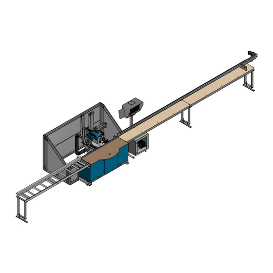
Page 28: Parts Identification
10 Parts Identification 10.1 Top Level Assembly Figure 5, CSS Apollo Saw Operations Manual – Spida Gen X CSS Apollo Saw... -
Page 29: Table 6, Parts List - Css Apollo Saw
Table 6, Parts List – CSS Apollo Saw ITEM PART NUMBER DESCRIPTION 1 0605220 Monitor Stand Assembly 1 0609000 Multi Monitor Assembly 1 0609000FA Multi Monitor Stand 24" Wide Screen final assembly 1 1110000 Roller Table - 3m 1 1213000 - 06 Guide Profile Flat Table assembly 6m (20') 1 8830300 Arm Assembly - Apollo... -
Page 30: Automatic Stroke Limiter Assembly (Smpsl01)
10.2 Automatic Stroke Limiter Assembly (SMPSL01) Figure 6, Automatic Stroke Limiter Assembly Table 7, Automatic Stroke Limiter Assembly parts list ITEM PART NUMBER DESCRIPTION HWCSM410 Hex Socket Head Cap Screw M4x10 HWHA0448 Fixed lead block HWRF31712 Exit block HWRF661 Pulley SMPSL01-01 Stroke limiter main post SMPSL01-02... -
Page 31: Monitor Stand Assembly (0605220)
10.3 Monitor Stand Assembly (0605220) Figure 7, Monitor Stand Assembly Table 8, Monitor Stand Assembly parts list ITEM PART NUMBER DESCRIPTION 0605221 Monitor Stand Base Assembly 0609000 Multi Monitor Assembly 0609000FA Multi Monitor Stand 24" Wide Screen final assembly bits 0609003 Monitor Post welded assembly HWCSM816... -
Page 32: Multi Monitor Assembly (0609000)
10.4 Multi Monitor Assembly (0609000) Figure 8, Multi Monitor Assembly Note: The illustration above shows minimal wires for clarity, the actual Monitor Box will contain more wires. Component locations are subject to change. Table 9, Multi Monitor Assembly parts list ITEM PART NUMBER DESCRIPTION... -
Page 33: Roller Table Assembly (1110000 - 3000)
10.5 Roller Table Assembly (1110000 – 3000) Figure 9, Roller Table Assembly Table 10, Roller Table Assembly parts list ITEM PART NUMBER DESCRIPTION 1110001 Roller Table Frame - Fence Type V2 HWHBM1030 Hex bolt M10x30 HWNHM10 Hex nut M10 HWNHM16 Hex nut M16 HWRSD50355 Roller - Steel 50x355... -
Page 34: Rapid Stop Table (1213000)
10.6 Rapid Stop Table (1213000) Figure 10, Rapid Stop Table Operations Manual – Spida Gen X CSS Apollo Saw... -
Page 35: Table 11, Rapid Stop Table - Parts List
Table 11, Rapid Stop Table - Parts list ITEM PART NUMBER DESCRIPTION 0605220 Monitor Stand Assembly 0609000 Multi Monitor Assembly 0609000FA Multi Monitor Stand 24" Wide Screen final assembly bits 1213001 - 2000 Rapid Stop Table 2000 - Folded 1213001 - 3000 Rapid Stop Table 3000 - Folded ECOM-WES7G5 Computer Load with Spida software... -
Page 36: Fence Assembly (Smpgpfa6300)
10.6.1 Fence Assembly (SMPGPFA6300) Figure 11, Fence Assembly Operations Manual – Spida Gen X CSS Apollo Saw... -
Page 37: Table 12, Fence Assembly Parts List
Table 12, Fence Assembly parts list ITEM PART NUMBER DESCRIPTION BRG6005ZZ Bearing 47x25x12 HWCSM635 Hex Socket Head Cap Screw M6x35 HWCSM675 Hex Socket Head Cap Screw M6x75 HWCSM835CS Hex Socket CSK Cap Screw M8x35 HWGSM610 Hex socket grub screw M6x10 HWGSM825 Hex socket grub screw M8x25 MT21.1018... -
Page 38: Guide Profile Gearbox Kit (Smpgpgk5)
10.6.2 Guide Profile Gearbox Kit (SMPGPGK5) Figure 12, Gearbox Motor Assembly Table 13, Gearbox Motor Assembly - Parts list ITEM PART NUMBER DESCRIPTION 4 HWCSM416 Cap Screw - M4x16 ZP 4 HWCSM525 Hex Socket Head Cap Screw M5x25 4 HWCSM630CS Countersunk Cap Screw M6x30 4 HWCSM830CS Hex Socket CSK Cap Screw M8x30... -
Page 39: Guide Profile Trolley Kit (Smpgptk1)
10.6.3 Guide Profile Trolley Kit (SMPGPTK1) Figure 13, Guide Profile Trolley Assembly Table 14, Guide Profile Trolley Assembly parts list ITEM LENGTH PART NUMBER DESCRIPTION HWCSM816BH Button Head Cap Screw M8x16 HWCSM820BH Button Head Screw M8x20 HWCSM825 Hex Socket Head Cap Screw M8x25 HWWFM816 Flat Washer M8 MT21.1018... -
Page 40: Arm Assembly - Apollo (8830300)
10.7 Arm Assembly – Apollo (8830300) Figure 14, Arm Assembly Operations Manual – Spida Gen X CSS Apollo Saw... -
Page 41: Table 15, Arm Assembly Parts List
Table 15, Arm Assembly parts list ITEM PART NUMBER DESCRIPTION 8530310 Spring Boss 8530311 Return Spring - CXM "C" Type 8530314 Lock Washer - 5/8 8830315 Metric Arm Pin 8830316 Arm set long pin 8830321 Rear Top Arm - Apollo 8830322 Rear Side Arm - Apollo 8830323... -
Page 42: Apollo Saw Base To Column Post Assembly (8832100)
10.8 Apollo saw Base to Column Post Assembly (8832100) Figure 15, Base to Column post Assembly Operations Manual – Spida Gen X CSS Apollo Saw... -
Page 43: Table 16, Base To Column Post Assembly Parts List
Table 16, Base to Column post Assembly parts list ITEM PART NUMBER DESCRIPTION 8530104 Fence Locating Bracket 8530115 Top Bearing Pin. 70mm Dia. BCQ 8530116 Bottom Pin 8530124 Radial Plate 8530128 Radial Degree Scale 8530134 Jacking Plate 8530350 Dust Chute - CSS - Grey RAL7035 8530352 Chute Adaptor 8830123... - Page 44 HWWSM8 Washer - Spring - Curved - M8 ZP HWWSM12 Washer - Spring - Curved - M12 ZP HWWSM20 Washer - Spring - M20 ZP SMPBF301 Base 1750 Wide SMPBT1750-460-25 Bench Top 25mm MDF 1750mm long with radius front SMPDEC005 Forklift here - Decal SMPFE04 Fence CXL/CSS XL/Apollo 75mm high 1800mm...
-
Page 45: Apollo Saw Motor Group (8831400)
10.9 Apollo saw Motor Group (8831400) Figure 16, Motor Group Assembly Operations Manual – Spida Gen X CSS Apollo Saw... -
Page 46: Table 17, Motor Group Assembly Parts List
Table 17, Motor Group Assembly parts list ITEM PART NUMBER DESCRIPTION 8530407 T-bolt M10x22 8530408 T-bolt M10x32 8530414 Motor Jacking Pads 8532400 - K1 Height Adjust Assembly - Vector 8532404 Guard Door 8532405 Motor Guard BL4503566 Blade - 450mm x 35mm Bore x 72tt (CSS) EM5.5LMULTI CEG Motor - EM80M,5.5Kw, Multi Left Hand ESS RHS... -
Page 47: Height Adjust Assembly (8532400 - K1)
10.9.1 Height Adjust Assembly (8532400 – K1) Figure 17, Height Adjust Assembly Operations Manual – Spida Gen X CSS Apollo Saw... -
Page 48: Table 18, Height Adjust Assembly Parts List
Table 18, Height Adjust Assembly parts list ITEM PART NUMBER DESCRIPTION 8831400 - K4 CXM Motor Kit 8530401 Height Adj Shaft 8530403 Slide MMB - Drilled 8530404 Slide MMB -Slotted 8530405 Pressure Plate 8530406 Pressure Bar 8532400 - K2 Blade Guard Assy - 450 8532401 Motor Mount Pivot Plate Assy - Vector 8532402... -
Page 49: Automation Parts For C Type - Css Xl Saw (9804200)
10.10 Automation Parts for C type – CSS XL saw (9804200) Figure 18, Automation Assembly Table 19, Automation Assembly parts list ITEM PART NUMBER DESCRIPTION 1 9103603 Column Support Cover (SS 2mm) 1 9801616 Front Guard Left - CSS XL (MS 2mm) 1 9801617 Front Guard Right - CSS XL (MS 2mm) 1 9801620... -
Page 50: Rotation Assembly (Trrak7)
10.10.1 Rotation Assembly (TRRAK7) Figure 19, Rotation assembly Operations Manual – Spida Gen X CSS Apollo Saw... -
Page 51: Table 20, Rotation Assembly Parts List
Table 20, Rotation assembly parts list ITEM QTY PART NUMBER DESCRIPTION 1 8530105 Spanner locating pin 4 BRG6201 Bearing 32x12x10 2 HWCSM612BH Button Head Cap Screw M6x12 4 HWCSM820 Hex Socket Head Cap Screw M8x20 4 HWCSM830 Hex Socket Head Cap Screw M8x30 2 HWNHM12 Hex nut M12 2 HWWFM616... -
Page 52: Apollo - Rear Guard Assembly (9804400)
10.11 Apollo – Rear Guard Assembly (9804400) Figure 20, Rear guard assembly Operations Manual – Spida Gen X CSS Apollo Saw... -
Page 53: Table 21, Rear Guard Parts List
Table 21, Rear guard parts list ITEM QTY PART NUMBER DESCRIPTION 9804401 Apollo Guard - Rear Infill - 2583x621 (4mm ACM Board) 9804402 Apollo Guard - Front Infill - 338x557 (4mm ACM Board) 9804403 Apollo Guard - Door Infill - 918x1213(Angle) (4mm ACM Board) 9804404 Apollo Guard - Joiner Plate (3mm SS Profile) 9804405... -
Page 54: Maintenance
If a part is damaged substantially, or if anything covered in this maintenance section cannot be fixed by general maintenance; then do not use the CSS Apollo Saw and contact a supervisor, maintenance engineer, or Spida Machinery. Table 22, Maintenance intervals... -
Page 55: Maintenance Items
11.1 Maintenance Items 11.1.1 Guards Check Guards are in place, and they are tight, with no loose bolts. Guards should always be operational. 11.1.2 Keep work area clear Ensure that the area surrounding the CSS Apollo Saw is free of trip hazards, unnecessary tools, or other debris. -
Page 56: Sensors
11.1.5 Sensors Check the three proximity sensors (on the Rapid Stop, Rotation ring, and on the back of the arms), are clear of any build-up of dust and securely fastened; sensor malfunctions will prevent the CSS Apollo Saw from working correctly. If any of the sensors are loose, check the sensors are still located correctly and that there is a 1.5 –... -
Page 57: Height Adjusts And Blade Guard Assemblies
11.1.11 Height adjusts and Blade Guard Assemblies The height adjust assembly should move the saw blade up and down easily as required, and the blade guard assembly should allow the saw blade to spin and cut easily while protecting the user from the saw blade. -
Page 58: Inspect Timing Belt (Rapid Stop)
The cables should run through all pulleys easily and should not be twisted; Realign onto pulleys or untwist as required. Check the cable, pulleys, and other components for excessive wear; repair/replace as required, or alternatively contact Spida Machinery. 11.1.18... -
Page 59: Replace Saw Blade
Barrier Guard Table 23, Blade Replacement parts Figure 22, Blade Replacement Replacement blades, 450mm Dia. 35mm bore 72 teeth Spida Machinery part number BL4503566. Contact Spida Machinery for replacement blades. Before starting make sure machine is isolated electrically. To replace the blade in saw: •... -
Page 60: Set Proximity Position
11.3 Set Proximity position The Proximity Sensor position will need to be reset whenever a sensor, lead or bracket is replaced. Tools Required (for all 3 configurations): 2x 17mm Spanners (to tighten sensors) 11.3.1 Rapid Stop Proximity Sensor Configuration Figure 23, Rapid Stop proximity sensor configuration •... -
Page 61: Arm Assembly Proximity Sensor Configuration
11.3.2 Arm Assembly Proximity Sensor Configuration Figure 24, Arm Assembly proximity sensor configuration • Power off Saw and Rapid Stop. • Push the Blade guard back until the arm assembly is as close together as possible. • Ensure that the proximity sensor is in the middle of the back arm as shown in Figure 24. •... -
Page 62: Rotation Ring Proximity Sensor Configuration
11.3.3 Rotation Ring Proximity Sensor Configuration Figure 25, Rotation Ring proximity sensor configuration • Power off Saw and Rapid Stop. • Push the Rotation assembly over until the sensor plate is above the proximity sensor on the rotation motor assembly. See Figure 25. •... -
Page 63: Replacing Trolley Slides
11.4 Replacing Trolley Slides Figure 26, Trolley slide replacement Tools required: Set of Allan keys • Disconnect power. • Disconnect lead and remove home sensor. • Disconnect leads from and remove motor. • Undo 16 cap screws holding fence assy. •... -
Page 64: Reference Distances For Trolley Sliders
11.4.1 Reference Distances for Trolley sliders Figure 27, Stop Slider distances The above figure shows the required distances in mm between the sliders, and between the slider and the end of the Stop. Use these distances when the sliders need to be removed for maintenance. Operations Manual –... -
Page 65: Replace Rotation Belt
11.5 Replace Rotation Belt Tools required: Set of Allan keys 1” Spanner (supplied) 19mm Spanner Figure 28, Rotation Motor Assembly • Remove saw tabletop and blue guard plate in front of gearbox. • Rotate saw to the left until the gearbox and belt adjusting rollers are accessible from the top. •... -
Page 66: Replace Motor Brake
11.6 Replace Motor Brake When replacing the Motor brake on the Arbor motor, be sure to follow the instructions provided below depending on the type of brake being used: 11.6.1 FPC Brake Figure 29, Connection Diagram for FPC Brake Brake adjustment (or braking gap adjustment – r) Adjust the screw until you achieve the braking gap value listed on the table below. -
Page 67: 100V Brakes
11.6.2 100V Brakes Connecting 100V Brakes on CEG Motors • It is vitally important to ensure you have the correct connection of the motor brake to prevent damage to the brake. • The Rectifier supplied is suitable for any mains Voltage supplied, it approximately halves the supply Alternating Voltage to DC (240V AC becomes ~100VDC and 415V AC becomes ~ 190VDC) •... -
Page 68: 190V Brakes
11.6.3 190V Brakes Connecting 190V Brakes on CEG Motors • It is vitally important to ensure you have the correct connection of the motor brake to prevent damage to the brake. • The Rectifier supplied is suitable for any mains Voltage supplied, it approximately halves the supply Alternating Voltage to DC (240V AC becomes ~100VDC and 415V AC becomes ~ 190VDC) •... -
Page 69: Test Cuts (If Required)
11.7 Test Cuts (If required) If a test cut is required by Spida Machinery, the following steps must be carried out. If there are any other issues with the CSS Vector/Apollo Saw, then contact Spida Machinery accordingly. Testing the Cut Accuracy To ensure the machine is cutting accurately, it is necessary to check that the right-hand side of the blade, the front face of the fence, and the centre of the top pin are aligned. -
Page 70: Figure 32, Fence Too Far Back
NOTE: The Left side of the saw cuts should align, irrespective of the side the outfeed is located. 8. If the point of intersection is too far back or forward, adjustment can be made at the fence. To adjust the fence, loosen the 8mm Countersunk Cap screws holding the fence to the base frame, on either side of the fence. -
Page 71: Motor Alignment
The Right side of the saw cuts should intersect, irrespective of the side the outfeed is located. If the cuts are not correct, please contact Spida Machinery for further information. It is not recommended to attempt to adjust the motor alignment without guidance... -
Page 72: Foreseeable Misuse
12 Foreseeable Misuse Through experience, Spida Machinery’s technical staff have listed (in order of occurrence) the most common misuses of the machinery by operators, the symptoms that result and the rectification required to address the misuse and return the machine to optimal working order. -
Page 73: Trouble Shooting
Brake stuck Lock out air and power to the machine. Check brake and attached parts, and repair and replace as required. Remove any obstructions. Contact Spida Machinery if there is a major issue. Overload tripped Check overload setting. Reset overload... - Page 74 Check input cables. If any of the above corrections do not solve the issue, then do not use the Saw and contact a supervisor, maintenance engineer, or Spida Machinery. Operations Manual – Spida Gen X CSS Apollo Saw...
-
Page 75: Distributor & Repairer Contacts
14 Distributor & Repairer Contacts 14.1 Agent/Distributor Company Name: ____________________________________________________________________ Address: __________________________________________________________________________ Contact Person: ____________________________________________________________________ Ph.: _____________________________________ Fax: ______________________________________ Mobile: _________________________________ Email: ____________________________________ 14.2 Automation Repairs Company Name: ____________________________________________________________________ Address: __________________________________________________________________________ Contact Person: ____________________________________________________________________ Ph.: _____________________________________ Fax: ______________________________________ Mobile: _________________________________ Email: ____________________________________ 14.3 Mechanical Repairs Company Name: ____________________________________________________________________ Address: __________________________________________________________________________... -
Page 76: Warranty
15 Warranty M2012 Ltd, SPIDA Machinery, Tauranga, New Zealand, warrants the equipment listed below to the initial purchaser of the equipment only against defective workmanship and materials only, for a period of twelve (12) months from the date of shipment from SPIDA's factory, subject to the following conditions: SPIDA extends the original manufacturer’s warranty to SPIDA on buy-in items such as... - Page 77 Machinery/Equipment The item bearing the following serial plate: _____________________________________ Date of Shipment: ______________________________________ Signed by: ______________________________________ Name: ______________________________________ Position: ______________________________________ Acceptance of Warranty I acknowledge and accept the contents of this warranty. Signed by: ______________________________________ Name: ______________________________________ Company: ______________________________________ Position: ______________________________________ Date: ______________________________________...
-
Page 78: Electrical Drawings - Nz/Au
16 Electrical Drawings – NZ/AU Figure 35, Apollo Electrical Drawings NZ/AU part 1 Operations Manual – Spida Gen X CSS Apollo Saw... -
Page 79: Figure 36, Apollo Electrical Drawings Nz/Au Part 2
Figure 36, Apollo Electrical Drawings NZ/AU part 2 Operations Manual – Spida Gen X CSS Apollo Saw... -
Page 80: Figure 37, Apollo Electrical Drawings Nz/Au Part 3
Figure 37, Apollo Electrical Drawings NZ/AU part 3 Operations Manual – Spida Gen X CSS Apollo Saw... -
Page 81: Figure 38, Apollo Electrical Drawings Nz/Au Part 4
Figure 38, Apollo Electrical Drawings NZ/AU part 4 Operations Manual – Spida Gen X CSS Apollo Saw... -
Page 82: Figure 39, Apollo Electrical Drawings Nz/Au Part 5
Figure 39, Apollo Electrical Drawings NZ/AU part 5 Operations Manual – Spida Gen X CSS Apollo Saw... -
Page 83: Figure 40, Apollo Electrical Drawings Nz0Au Part 6
Figure 40, Apollo Electrical Drawings NZ0AU part 6 Operations Manual – Spida Gen X CSS Apollo Saw... -
Page 84: Figure 41, Apollo Electrical Drawings Nz/Au Part 7
Figure 41, Apollo Electrical Drawings NZ/AU part 7 Operations Manual – Spida Gen X CSS Apollo Saw... -
Page 85: Ce Declaration Of Conformity
17 CE Declaration of Conformity Figure 42, CE Declaration of conformity. Operations Manual – Spida Gen X CSS Apollo Saw... -
Page 86: Training Certificate - Apollo Saw
18 Training Certificate – Apollo Saw Instructor: ___________________________________ Company: ___________________________________ I declare that: • I have trained the person names below (“the trainee”) in the safe operation of the machinery/equipment detailed in the training manual. • The trainee has demonstrated an understanding of the safe operation of the machinery/equipment.
Need help?
Do you have a question about the Apollo Gen10 and is the answer not in the manual?
Questions and answers