
Related Manuals for Ihse Draco U-Switch


Summary of Contents for Ihse Draco U-Switch
- Page 1 USER MANUAL Draco U-Switch U-Switch Module B476-4U4T Document B476-4U4T_REV02.00_en Edition: 2021-10-14...
- Page 2 Read carefully through the User Manual before you switch on the product. The model and serial number of your products are indicated on the bottom of our products. Always refer to this information when you need to contact your dealer or the support of IHSE GmbH (see chapter 12, page 57).
-
Page 3: Table Of Contents
Draco U-Switch Table of Contents Table of Contents Important Information ............................ 6 Firmware and Software ........................6 Symbols for Warnings and Helpful Information ................... 6 Terms and Spellings ..........................7 EU Declaration of Conformity ......................7 Safety instructions ............................8 Description .............................. - Page 4 Table of Contents Draco U-Switch 3.13 Status Indication of the U-Switch Module B476-4U4T ............... 30 Access Options ............................31 Command Mode ..........................31 Management Software ........................33 Installation ..............................34 Setting up the System ........................34 5.1.1 Setting up the U-Switch ...................... 34 5.1.2...
- Page 5 Draco U-Switch Table of Contents 12.1.3 Mini-USB ..........................57 12.1.4 GPIO ........................... 57 12.2 Connector Pinouts ..........................58 12.2.1 USB, Type A ........................58 12.2.2 USB, Type B ........................58 12.2.3 Mini-USB, Type B ....................... 58 12.2.4 D-Sub 9 (GPIO) ........................58 12.2.5...
-
Page 6: Important Information
Table of Contents Draco U-Switch Important Information The manual is updated when firmware or software changes affect user behavior or system behavior. Please refer to the change log (see chapter 0, page 67) for user manual updates. Firmware and Software The firmware and software version described in this user manual are listed below. -
Page 7: Terms And Spellings
Draco U-Switch Important Information Terms and Spellings Uniform terms are used in this manual for better readability or easier assignment. The following terms are used for products and system descriptions: Term Description Management software Tera Tool Source Computer, graphic card... -
Page 8: Safety Instructions
Table of Contents Draco U-Switch Safety instructions To ensure reliable and safe long-term operation of your device, please note the following guidelines: Read this user manual carefully. Only use the device according to this user manual. Failure to follow the instructions described can damage the device or endanger the security of your data. - Page 9 Draco U-Switch Safety instructions Connection Check the device and the power supply units for visible damage before connecting it. Only use the device or power supply units without any visible damage at the chassis or the cable. Only use power supply units originally supplied with the product or manufacturer-approved replacements.
-
Page 10: Description
Table of Contents Draco U-Switch Description Intended Use The U-Switch product line is designed to seamlessly control multiple sources as one using just a single set of keyboard and mouse while the sources video outputs are connected straight to the monitors. -
Page 11: System Overview With Installation Examples
Draco U-Switch Description System Overview with Installation Examples 3.2.1 Direct Connection The U-Switch is connected to sources using the cables supplied. Keyboard and mouse are connected to the U-Switch. Fig. 1 System overview - Example direct source connection Sources with connected monitors... -
Page 12: Direct Connection With External Switching Solution
Table of Contents Draco U-Switch 3.2.2 Direct Connection with external Switching Solution The U-Switch is connected to sources using the cables supplied. Keyboard and mouse are connected to the U-Switch. An external switching solution is connected to the optional GPIO module. -
Page 13: Chassis
Draco U-Switch Description Chassis Mounting Chassis Chassis Power supply unit Active Setup for redundant Type Slots backplane Current input Internal External power supply voltage 474-BODY2 Interface side 474-BODY2R Interface side 1x (external) 474-BODY2N Interface side 1x (external) 474-BODY4 Interface side... -
Page 14: Accessories For The Chassis
Spare ext. PSU for 474-BODY6R-R1 474-PSU21 Spare PSU for 474-BODY21/4U, slide-in, hot-swap 474-BLND1 Blanking plate with IHSE Logo, 1-slot for Draco vario chassis 474-6FAN Optional fan for Draco vario 2-slot and 6-slot chassis with backplane 260-5G International power supply unit 100...240VAC/5VDC/3A 260-5M International power supply unit 100...240VAC/5VDC/5A... -
Page 15: Scope Of Delivery
Draco U-Switch Description Scope of Delivery Depending on the order, the scope of delivery contains the following items: Product type Scope of delivery B476-4U4T • 4x USB cable 1.8 m (type A-B) • Quick Setup Per each Draco vario 474-BODY2, •... -
Page 16: Device Views Draco Vario Chassis
Table of Contents Draco U-Switch Device Views Draco vario Chassis NOTICE Exceeding the maximum permissible power consumption In addition to the power consumption of the used modules, the power consumption of the connected peripherals must be added. Note the maximum power consumption of the chassis (see chapter 12.3.1, page 59 and chapter 12.3.2, page 59). -
Page 17: 2-Slot Chassis Draco Vario 474-Body2N
Draco U-Switch Description 3.9.3 2-Slot Chassis Draco vario 474-BODY2N Fig. 6 Interface side chassis 474-BODY2N Slot 1 Power supply voltage 1, AC Slot 2 Power supply voltage 2, DC NOTICE Excessive current draw The 2-slot Draco vario chassis with an internal power supply unit is not equipped with a fuse on its primary side. -
Page 18: 4-Slot Chassis Draco Vario 474-Body4R
Table of Contents Draco U-Switch 3.9.6 4-Slot Chassis Draco vario 474-BODY4R Fig. 9 Interface side chassis 474-BODY4R Slot 1 Power supply voltage 2, DC Slot 2 Power supply voltage 1, DC Slot 3 Slot 4 3.9.7 6-Slot Chassis Draco vario 474-BODY6R-R1 Fig. -
Page 19: 6-Slot Chassis Draco Vario 474-Body6Bp
Draco U-Switch Description 3.9.8 6-Slot Chassis Draco vario 474-BODY6BP Fig. 11 Interface side chassis 474-BODY6BP Slot 1 Slot 4 Slot 2 Slot 5 Slot 3 Slot 6 Fig. 12 Rear view chassis 474-BODY6BP Power supply voltage 1, AC Grounding Power supply voltage 2, AC 3.9.9... -
Page 20: 21-Slot Chassis Draco Vario 474-Body21/4U And 474-Body21/4U
Table of Contents Draco U-Switch 3.9.10 21-Slot Chassis Draco vario 474-BODY21/4U and 474-BODY21/4U Fig. 14 Interface side chassis 474-BODY21/4U and 474-BODY21/4U Slots 1 to 21 (from left to right) The chassis 474-BODY21/4U is supplied with one power supply unit (Pos. 3). A second power supply unit can be optionally installed. -
Page 21: Device View U-Switch Module B476-4U4T
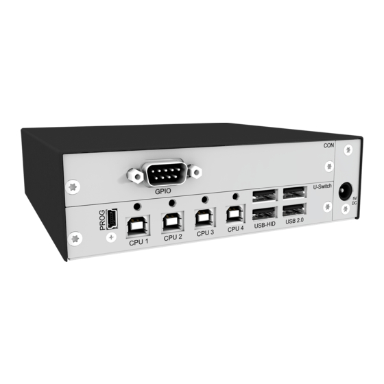
Draco U-Switch Description 3.10 Device View U-Switch Module B476-4U4T Fig. 16 Interface side U-Switch module B476-4U4T Input Mini-USB (service) CPU 4: Output USB-HID and USB 2.0 CPU 1: Output USB-HID and USB 2.0 Input / Output USB-HID CPU 2: Output USB-HID and USB 2.0 Input / Output USB 2.0 (up to 480 Mbit/s) -
Page 22: Status Indication Of The Chassis
Table of Contents Draco U-Switch 3.12 Status Indication of the Chassis 3.12.1 Status LED 2-Slot-Chassis Draco vario 474-BODY2 Fig. 18 Interface side chassis 474-BODY2 - Status LED Status LED supply voltage 1 Status LED for Power Supply Voltage The following table shows the LED states/colors for the power supply voltage (see chapter 3.9.1, page 16). -
Page 23: Status Leds 2-Slot-Chassis Draco Vario 474-Body2N
Draco U-Switch Description 3.12.3 Status LEDs 2-Slot-Chassis Draco vario 474-BODY2N Fig. 20 Interface side chassis 474-BODY2N - Status LEDs Status LED power supply voltage 1 Status LED power supply voltage 2 Status LEDs for Power Supply Voltage The following tables show the LED states/colors for the power supply voltage (see chapter 3.9.3, page 17). -
Page 24: Status Leds 2-Slot-Chassis Draco Vario 474-Body2Bpf
Table of Contents Draco U-Switch 3.12.4 Status LEDs 2-Slot-Chassis Draco vario 474-BODY2BPF Fig. 21 Interface side chassis 474-BODY2BPF - Status LEDs Status LED power supply voltage 1 Status LED power supply voltage 2 Status LEDs for Power Supply Voltage The following tables show the LED states/colors for the power supply voltage (see chapter 3.9.4 page 17). -
Page 25: Status Led 4-Slot-Chassis Draco Vario 474-Body4
Draco U-Switch Description 3.12.5 Status LED 4-Slot-Chassis Draco vario 474-BODY4 Fig. 22 Interface side chassis 474-BODY4 - Status LEDs Status LED power supply voltage 1 Status LED for Power Supply Voltage The following table shows the LED states/colors for the power supply voltage (see chapter 3.9.5, page 17). -
Page 26: Status-Leds 6-Slot-Chassis Draco Vario 474-Body6R-R1
Table of Contents Draco U-Switch 3.12.7 Status-LEDs 6-Slot-Chassis Draco vario 474-BODY6R-R1 Fig. 24 Interface side chassis 474-BODY6R-R1 - Status LEDs Status LED power supply voltage 1 Status LED power supply voltage 2 Status LEDs for Power Supply Voltage The following tables show the LED states/colors for the power supply voltage (see chapter 3.9.7 page 18). -
Page 27: Status Leds 6-Slot Chassis Draco Vario 474-Body2Bpf/474-Body6Bp
Draco U-Switch Description 3.12.8 Status LEDs 6-Slot Chassis Draco vario 474-BODY2BPF/474-BODY6BP Fig. 25 Interface side chassis 474-BODY6BP - Status LEDs Status LED power supply voltage 1 Status LED power supply voltage 2 Status LEDs for Power Supply Voltage The following tables show the LED states/colors for the power supply voltage (see chapter 3.9.8 page 19). -
Page 28: Status Leds 6-Slot-Chassis Draco Vario 474-Body6Bpf
Table of Contents Draco U-Switch 3.12.9 Status LEDs 6-Slot-Chassis Draco vario 474-BODY6BPF Fig. 26 Interface side chassis 474-BODY6BPF - Status LEDs Status LED power supply voltage 1 Status LED power supply voltage 2 Fig. 27 Rear view chassis 474-BODY6BPF - Status LEDs... -
Page 29: Status Leds 21-Slot Chassis Draco Vario 474-Body21/4U And 474-Body21/4Ur
Draco U-Switch Description 3.12.10 Status LEDs 21-Slot Chassis Draco vario 474-BODY21/4U and 474-BODY21/4UR Fig. 28 Rear side chassis 474-BODY21/4U und 474-BODY21/4UR - Status LEDs Status LED power supply voltage 2 (redundancy) Status LED power supply voltage 1 Fault LED power supply voltage 2 (redundancy) Fault LED power supply voltage 1 The following tables show the LED states/colors for the power supply voltage (see chapter 3.9.10 page 20). -
Page 30: Status Indication Of The U-Switch Module B476-4U4T
Table of Contents Draco U-Switch 3.13 Status Indication of the U-Switch Module B476-4U4T Fig. 29 Interface side U-Switch module B476-4U4T - Status LED Status LED for switching status Status LED for the Switching Status Pos. Status Description Status 1x flashing Switched to CPU 1... -
Page 31: Access Options
Description Command mode Connected CON extender modules include a command mode that enables access to several functions of connected KVM devices, e.g., Draco U-Switch when using additional keyboard commands. Management software Connecting the U-Switch to the Tera Tool (below referred to as “management software”) allows to configure the Multi-Screen Control (referred to as “MSC”... - Page 32 Table of Contents Draco U-Switch The following keyboard commands are used to enter, and to exit the command mode, and to change the Hot Key. Function Keyboard command Start the command 2x Left Shift (Hot Key, factory setting) mode (default)
-
Page 33: Management Software
Draco U-Switch Access Options Management Software The menu structure of the management software is subdivided into various sections. Fig. 30 Management software Menu structure Menu bar (top line) Toolbar (second line) -
Page 34: Installation
Table of Contents Draco U-Switch Installation NOTICE Please verify that interconnect cables, interfaces, and handling of the devices comply with the requirements (see chapter 0, page 48). First-time users are recommended to set up the system in a test environment that is limited to a single room. -
Page 35: Connecting To The U-Switch Via Management Software
Draco U-Switch Installation Connecting to the U-Switch via Management Software 5.2.1 Installing the Management Software The management software is available as a single executable program file (desktop) that does not require installation. The management software can be used to configure the U-Switch and to update the firmware of the U-Switch. -
Page 36: Connecting The U-Switch To The Computer
Table of Contents Draco U-Switch 5.2.2 Connecting the U-Switch to the Computer Connect the Mini-USB cable to the Mini-USB port of the U-Switch and the USB-A port of the computer. 5.2.3 Starting the Management Software Run the management software by a double-click on the program icon on the desktop or the file in the directory. -
Page 37: Configuration
Draco U-Switch Configuration Configuration Configuring the Multi-Screen Control The U-Switch can be flexibly configured for the use of MSC via management software, also the possibility of switching via mouse panning. To configure the U-Switch, proceed as follows: 1. Execute the management software on your computer. - Page 38 Table of Contents Draco U-Switch 9. The displays can be adjusted in terms of size, if required. Therefore, use the mouse and drag the monitors into the appropriate size by using the selection points. See examples for display sizing on the following page.
- Page 39 Draco U-Switch Configuration Arrangement example if using different display sizes If the used displays have different sizes, the display size should be set in the grid according to the real size of the displays. Fig. 35 Multi-Screen Control Configuration - Correct display arrangement...
-
Page 40: Activating/Deactivating The Routing Of Usb-2.0-Ports
Table of Contents Draco U-Switch Activating/Deactivating the Routing of USB-2.0-Ports To activate or deactivate the routing of the USB 2.0 ports to the four USB-B ports, a parameter can be entered in the configuration file ( Config.txt ). Configuration File The U-Switch contains a configuration file ( Config.txt ) to set specific parameters. - Page 41 Draco U-Switch Configuration Entering or Changing a Parameter in the Configuration File To enter or change a parameter of the U-Switch, proceed as follows: 1. Connect the U-Switch to any source using a Mini-USB cable. The U-Switch opens a flash drive containing the Config.txt file.
-
Page 42: Operation
Table of Contents Draco U-Switch Operation Switching via Keyboard The MSC function contains a switching of the USB-HID control between different statically connected sources and displays and can be performed via keyboard or mouse (see chapter 7.2, page 43). To perform a switching operation via keyboard command, proceed as follows: 1. -
Page 43: Switching Via Multi-Screen Control
Draco U-Switch Operation Switching via Multi-Screen Control When using sources in multi-head operation (e.g., Dual-Head), the switching is only working manually via keyboard commands. Any non-observance may have a negative influence on the stability of the system. The function cannot be guaranteed when using wireless keyboards and mice. -
Page 44: Activating And Deactivating The Switching Via Mouse
Table of Contents Draco U-Switch 7.2.1 Activating and Deactivating the Switching via Mouse Example 1 With, e.g., mode 2 set in the Config.txt , the U-Switch starts with a setting for a vertical display arrangement and enabled modes for switching via mouse in the horizontal or block display arrangements. -
Page 45: Setting And Using The Restricted Automatic Mode Of Switching Via Mouse
Draco U-Switch Operation 7.2.2 Setting and Using the restricted Automatic Mode of Switching via Mouse Setting the Manual Mode is only available in the modes 1, 2, 3, and 4. Activating the restricted Automatic Mode If you want to avoid unintentional switching via mouse while MSC is activated, proceed as follows: 1. -
Page 46: Using A Usb 2.0 Device
Table of Contents Draco U-Switch Using a USB 2.0 Device When connecting a USB 2.0 device, e.g., a media control to the transparent USB 2.0 interfaces, the media control cannot interact with the U-Switch. The media control will just be routed through to the target computer. -
Page 47: Summary Of Keyboard Commands
Draco U-Switch Summary of Keyboard Commands Summary of Keyboard Commands Keyboard commands are fixed to the position of the keys on the keyboard. Keyboard mapping tables may vary for country-specific layouts. Note the key position of keys when changing the keyboard layout, e.g., from QWERTZ to AZERTY with the French keyboard layout. -
Page 48: Switching
Table of Contents Draco U-Switch Switching 8.2.1 Restricting the Automatic Switching with activated MSC Keyboard command Function Hot Key, x, m, Enter With activated MSC restrict the automatic switching and enable the manual mode. The mouse cannot be moved over the edge of a screen. -
Page 49: Maintenance
Draco U-Switch Maintenance Maintenance Maintening the Hardware NOTICE Possible damage to the mechanical and electronic components The chassis contains no serviceable parts inside. If the chassis is nevertheless opened and damaged in the process, the manufacturer's warranty is voided. The chassis, the extender modules and add-on modules as well as the accessories can be damaged by cleaning with damp or aggressive cleaning agents. - Page 50 Table of Contents Draco U-Switch 4. Click KM-Switch Update via Mini-USB flash drive. Fig. 39 Management software Flash Update The update dialog appears. 5. Connect the U-Switch to your computer via Mini-USB cable. 6. Power up the U-Switch. 7. Click Search KM-Switch.
- Page 51 Draco U-Switch Maintenance 9. Click Next > after successful identification. Fig. 41 Management software Flash Update - Identify KM-Switch Type 10. Click Browse… to navigate to the location the update files are saved. 11. Select the update files and click Select in the selection dialog.
- Page 52 Table of Contents Draco U-Switch 13. Click Next > to verify the update. Fig. 43 Management software Flash Update - Update KM-Switch - Update completed A green highlighted message will appear after the firmware update has been completed. 14. Click Next > to verify the update.
-
Page 53: Updating The U-Switch Firmware Via Copy & Paste
Draco U-Switch Maintenance 16. Remove the Mini-USB cable from the U-Switch. 17. Reconnect the USB cables to the U-Switch with the power switched off. 18. Reconnect the power cord of the U-Switch. The U-Switch validation will start automatically. 19. Click Finish. - Page 54 Table of Contents Draco U-Switch Preserving the Parameters of the Config.txt To optionally store the Config.txt before updating HUSWMSD.pfw firmware, if the MSC has been configured and/or if parameters have been set, proceed as follows: 1. Connect the U-Switch to your computer using a Mini-USB cable.
-
Page 55: Resetting The U-Switch To The Factory Settings
Draco U-Switch Resetting the U-Switch to the Factory Settings NOTICE If a firmware update has been carried out since the delivery, this firmware version is retained. To reset the U-Switch back to default settings, proceed as follows: 1. Connect the U-Switch to any source using a Mini-USB cable. -
Page 56: Troubleshooting Usb-Hid
Table of Contents Draco U-Switch Troubleshooting USB-HID Diagnosis Possible reason Measure Press Esc to leave the command mode. The Caps Lock and Keyboard in command mode Scroll Lock LEDs on the keyboard are flashing. USB device without No USB-HID device ... -
Page 57: Technical Data
Draco U-Switch Technical Data Technical Data 12.1 Interfaces 12.1.1 USB-HID Our devices with USB-HID interface support a maximum of two devices with USB-HID protocol. Each USB-HID port provides a maximum current of 100 mA. Keyboard Compatible with most USB keyboards. Certain keyboards with additional functions may require custom firmware to operate. -
Page 58: Connector Pinouts
Table of Contents Draco U-Switch 12.2 Connector Pinouts 12.2.1 USB, Type A Connector Signal Color +5 V (DC) White Green Black 12.2.2 USB, Type B Connector Signal Color +5 V (DC) White Green Black 12.2.3 Mini-USB, Type B Connector Signal... -
Page 59: Power Supply Voltage, Current Draw And Power Consumption
Draco U-Switch Technical Data 12.3 Power Supply Voltage, Current Draw and Power Consumption NOTICE Overheating of the power supply units In case of having redundant power supply units, the maximum current must not exceed the value of one of the two power supply units due to the heat dissipation. -
Page 60: Environmental Conditions And Emissions
Table of Contents Draco U-Switch 12.4 Environmental Conditions and Emissions Parameter Value Operating temperature 5 to 45 °C (41 to 113 °F) Storage temperature -25 to 60 °C (-13 to 140 °F) Relative humidity Max. 80% non-condensing Operating altitude Max. 2,500 m (7,500 ft) Sound pressure level Max. -
Page 61: Weight
Draco U-Switch Technical Data 12.6 Weight The following table contains the weight when the respective chassis is fully equipped, for both the CPU Unit and the CON Unit. 12.6.1 Weight of the Chassis Chassis Weight Weight inclusive shipping box 474-BODY2 / 0.7 kg (1.5 lb) -
Page 62: Technical Support
Table of Contents Draco U-Switch Technical Support Prior to contacting support, please ensure you have read this manual, and then installed and set-up your matrix as recommended. 13.1 Support Checklist To efficiently handle your request, it is necessary that you complete a support request checklist (Download). -
Page 63: Certificates/Directives
Draco U-Switch Certificates/Directives Certificates/Directives 14.1 North American Regulatory Compliance This equipment has been found to comply with the limits for a Class A digital device, pursuant to Part 15 of the FCC Rules. These limits are designed to provide reasonable protection against harmful interference when the equipment is operated in a commercial environment. -
Page 64: Glossary
Table of Contents Draco U-Switch Glossary The following terms are commonly used in this manual or in video and KVM technology. Term Description CON Unit Component of a KVM Extender or Media Extender to connect to the console (monitor(s), keyboard, and mouse; optionally also with USB 2.0 devices) -
Page 65: Table Of Figures
Draco U-Switch Table of Figures Table of Figures Fig. 1 System overview - Example direct source connection ..............11 Fig. 2 System overview - Example direct source connection with external switching solution ....12 Fig. 3 System overview - Example U-Switch in combination with KVM matrix switch......12 Fig. - Page 66 Table of Contents Draco U-Switch Fig. 42 Management software Flash Update - Update KM-Switch ............51 Fig. 43 Management software Flash Update - Update KM-Switch - Update completed ..... 52 Fig. 44 Management software Flash Update - Update KM-Switch - Update successful ....52...
-
Page 67: Change Log
Draco U-Switch Change log Change log This table offers an overview of the most important changes available through firmware updates, such as new functions, changed configuration or operation. Edition Date Chapter New functions / changes REV02.00 2021-10-14 8.2.3, 8.5, 8.5.1 New/changed chapters because of technical improvement or new features 8.4, 9...
Need help?
Do you have a question about the Draco U-Switch and is the answer not in the manual?
Questions and answers