Table of Contents
Advertisement
Quick Links
Advertisement
Table of Contents

Subscribe to Our Youtube Channel
Related Manuals for Compur Monitors Statox 506


Summary of Contents for Compur Monitors Statox 506
- Page 1 Statox 506 Sensor Head Operations Manual...
-
Page 2: Table Of Contents
Statox 506 Sensor Head Operations Manual Page SAFETY INSTRUCTIONS STATOX 506 CONSTRUCTION INSTALLATION AND CONNECTION Installation Electrical Connection 3.2.1 Statox 506 cable connection 3.2.2 Connection diagram with Statox 502/503 Control Module in the 2-wire mode 3.2.3 Connection diagram with Statox 502/503 Control Module in the 3-wire mode... -
Page 3: Safety Instructions
1 Safety Instructions Statox 506 is a transmitter designed as an intrinsically safe device, group 2 category II. It measures the concentration of toxic gases and oxygen in ambient air. It is safe to be operated in classified areas zone 1 and zone 2. -
Page 4: Statox 506 Construction
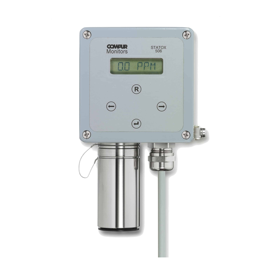
2 Statox 506 Construction Aluminium housing Display Ground contact Cable gland Sensor cover Dust filter (comes with the sensor) Filter holder Sensor (not part of the sensor head) Sensor socket Housing screws Keyboard Magnetic pin... -
Page 5: Installation And Connection
3 Installation and Connection 3.1 Installation Drilling plan and dimensions Statox 506 Statox 506 should be installed close to a potentially dangerous location or in between a dangerous location and a workplace. Some parameters may have an impact on the measurement: ... -
Page 6: Electrical Connection
Connect the ground contact to ground. It can take cables up to 4 mm². Reassure proper grounding. Use the optional pipe kit (see chapter 9) to install the sensor head to horizontal or vertical pipes. 3.2 Electrical Connection If installed in a classified area, the power supply must run through an intrinsically safe repeater. The combination Sensor head / repeater / cable must be within these parameters: Specifications: : Approved repeater specifications. -
Page 7: Statox 506 Cable Connection
2 mA and thus differentiate between system failure (critical error) and service mode (non - critical error). This is essential if you operate the Statox 506 as a safety operated system (SIS). See also chapter 6.3! If you operate the Statox 506 sensor head with a Statox 502 or 503 Control Module, use the schematics as shown in chapter 3.2.2 or 3.2.3. - Page 8 6 mm Strip the cable end as shown here. 50 mm Push the cable shield backwards and shorten it to 10-15 mm 10-15 mm. Push the metal spring onto the cable until it makes good contact with the shield. Push the cable into the cable gland to the end stop of the metal spring.
-
Page 9: Connection Diagram With Statox 502/503 Control Module In The 2-Wire Mode
Connection diagram with Statox 502/503 Control Module in the 2-wire mode Before connecting the Statox 506 to a Compur Statox 502 or Statox 503 Control Module, the appropriate program in the control module must be set. The programs are listed in the operation manual of the control module. -
Page 10: Connection Diagram With Statox 502/503 Control Module In The 3-Wire Mode
Connection diagram with Statox 502/503 Control Module in the 3-wire mode Before connecting the Statox 506 to a Compur Statox 502 or Statox 503 Control Module, the appropriate program in the control module must be set. The programs are listed in the operation manual of the control module. -
Page 11: Control Elements And Display
4 Control Elements and Display The display is an 8 digit 14-segment-LCD. You can program the sensor head by holding the magnetic pin on the control buttons: Symbol Name Function Increase value. Right Navigate to the right. Push and hold the contact for speed mode. Decrease value. -
Page 13: Menu
6 Menu 6.1 Main Menu Push the ENTER – button in order to enter the main menu. Use the left / right – buttons to enter the password “94”. This password cannot be changed. You can navigate in the main menu in either direction. Enter a sub menu by pushing the ENTER – button. RESET brings you step by step back into the measuring mode. - Page 14 Dial Code 94. If you enter a wrong code, the sensor head will return to the measuring mode. Now you are in the see 6.4 service mode. see 6.5 see 6.6 see 6.7 see 6.3 see 6.2 see 7...
-
Page 15: Setting The Real Time Clock
6.2 Setting the Real Time Clock The real time clock has been set ex-works. Probably you will have to adjust it to your local time. Only correct clock settings make sure that all alarm and calibration protocols are correct. ... -
Page 16: Current Output In The Service Mode
6.3 Current Output in the Service Mode The analog output can be set to 2 or 4 mA in the service mode. Here is a listing of all possible modes: Error Service Display at the Statox 503 (critical error) (non critical error) Control Module 2 mA... -
Page 17: Sensor Calibration
Sensor Calibration Sensor and sensor head must have the same temperature! For calibration you need the Statox 505/506 calibration adapter art # 570505, and an inert gas tube 4x1 mm (i.e. art. # 556710) and span gas (allowable concentration see chapter 12.2). If you are not sure that the ambient air is clean, you need synthetic air for zero adjustment. - Page 18 Statox 506 Calibration procedure...
-
Page 19: Prooftest
6.5 Prooftest The Prooftest checks the proper function of sensor and sensor head on a regular schedule. It cannot be used to test the entire alarm chain, because the analog signal is set to 2 or 4 mA. If you want to prooftest the entire alarm chain, this must be done in the measuring mode. -
Page 20: Info Menu
6.6 Info Menu Sub menu ALARM An alarm protocol starts as soon as the internal alarm threshold is exceeded. This threshold is sensor specific. Find a listing in capter 12.2. The memory can store only 3 alarm events. These parameters are stored: alarm start, concentration maximum, alarm end. -
Page 22: Test Menu
6.7 Test Menu The test menu helps you testing the sensor head itself and peripheral devices. Sub menu I-TEST You can set the analog output current to 4, 12 und 20 mA. Caution: Peripheral alarm devices might be triggered. Do not create unintended alarms! Sub menu LCD-TEST You can create different test - patterns on the display. - Page 23 Insert the filter as shown in the picture. Re–install the filter holder. The Statox 506 displays the actual concentration, even when it is still in the service mode. Push ENTER to return into the measuring mode. Timeout is 30 min.
-
Page 24: Maintenance And Cleaning
In case of doubt ask you local Compur representative. If you use Statox 506 as a SIL device according to standard DIN EN 61508, additional functional tests are required (see chapter 11). -
Page 25: Status- And Error Messages
10 Status- and Error Messages 10.1 Status Messages Anzeige Meaning Menu INFO most recent 3 alarms Best before date sensor calendar week / year Calibration. If this message flashes alternatingly with the measured value, a new calibration is required, because the most recent calibration has failed. - Page 26 Menu TEST: watchdog test start? (flashing) Menu TEST: watchdog test running Flashing alternatingly with the measured value: most recent zero adjustment has failed. Retry. Menu CALIB: zero adjustment Menu CALIB: flashing: zero stabilizing. Steady: zero found. Menu I-SERV: output current 2 mA in the service mode Menu I-SERV: 2 mA in the service mode have been programmed.
-
Page 27: Error Messages
10.2 Error Messages Any critical error reduces the output current to 2 mA (2-wire operation) or 0 mA (3-wire operation). Non critical errors may occur during maintenance procedures (e.g. calibration). They will not change the status. Error Character Reason Measure to be taken Ribbon cable loose or damaged. -
Page 28: Functional Safety
2. The user alone is responsible for the integration and the intended use of this system. 11.1 Safety Function Statox 506 detects toxic gases in the ppm range and oxygen in % volume range. It monitors the measured concentration also on an analog current output 0 – 22 mA: ... -
Page 29: Failure Rates And Safe Failure Fraction
11.8 Classification of the Safety Integrity Level (SIL) As specified in standard IEC 61508-2:2010 table 3, with a hardware failure tolerance (HFT) = 0 and a SFF of > 90 % the Statox 506 inclusive sensor complies with the requirements for a SIL 2 rating. 11.9 Lifetime The transmitter lifetime without sensor is determined to be 10 years. -
Page 30: Technical Data
X- Marking: requires potential equalization along the intrinsically safe loop. 12.2 Sensor Data Statox 506 sensors are solely electrochemical 2- or 3-electrode sensors. The listed parameters are typical data measured at 20°C, 50% r.F. and 1013 mbar. Response time has been measured with Statox 505/506 gas adapter at a flow of 20 l/h. -
Page 33: Eu-Declaration Of Conformity
13 EU-Declaration of Conformity... - Page 34 No licence is implied or in fact granted under the claims of any patent. Instruments are manufactured by Compur Monitors GmbH & Co. KG, Munich. The General Conditions of Supply and Service of Compur Monitors GmbH & Co. KG, Munich, are applicable.
Need help?
Do you have a question about the Statox 506 and is the answer not in the manual?
Questions and answers