
Subscribe to Our Youtube Channel
Related Manuals for Compur Monitors Statox 501 Infratox HS


Summary of Contents for Compur Monitors Statox 501 Infratox HS
- Page 1 Statox 501 Messkopf Infratox HS Statox 501 Sensor Head Infratox HS Bedienungsanleitung / Manual...
-
Page 2: Table Of Contents
Statox 501 Messkopf Infratox HS Statox 501 Sensor Head Infratox HS Bedienungsanleitung Manual Inhaltsverzeichnis Contents Sicherheitshinweise Safety instructions Aufbau und Funktionsbeschreibung Construction and function Montage und Anschluss Mounting and connections Montage der Wandhalterung Wall mounting Anschluss des Transmitters Connecting the transmitter Anschluss an das Statox 502/503 Control Modul Connection to the Statox 502/503 Control Module Anschluss an beliebige Controller oder ein PLS... -
Page 3: Sicherheitshinweise
Sicherheitshinweise Safety instructions Der explosionsgeschützte Statox 501 IR Transmitter der The Statox 501 IR is an explosion proof transmitter to be Gruppe II Kategorie 2 dient zur Konzentrationsmessung used in areas classified group II category 2. It measures the gas- und dampfförmiger Kohlenwasserstoffe bis zur concentration of combustible gases and vapors of unteren Explosionsgrenze. -
Page 4: Aufbau Und Funktionsbeschreibung
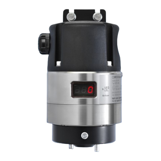
Aufbau und Funktionsbeschreibung Construction and Function 1 Mounting bracket 1 Wandhalterung 2 Kabelverschraubung 2 Cable gland 3 Grounding terminal 3 Erdungsklemme 4 Mittelteil inkl. Typenschild 4 Electronic compartment mit Seriennummer / Baujahr with type plate, 5 Unterteil mit Sensor serial number / date code 5 Sensor compartment 6 Öse für Halteband 7 Spritzschutz... -
Page 5: Montage Und Anschluss
Montage und Anschluss Mounting and Connections Montage der Wandhalterung Wall Mounting Bohrlöcher mit Hilfe der beiliegenden Bohrschablone Use the enclosed drilling plan to position the mounting holes. anbringen. Wandhalterung Transmittergehäuse Remove the mounting bracket / terminal box from the trennen und an der Wand befestigen. Wir empfehlen 6mm transmitter. -
Page 6: Anschluss An Das Statox 502/503 Control Modul
Anschluss an das Statox 502/503 Control Connection to the Statox 502/503 Control Modul Module Beachten Sie hierzu die Verdrahtungsschemata unter Observe the wiring diagrams shown in chapter 10 and the Abschnitt 10 und die Bedienungsanleitung des Control operations manual of the Control Module! Moduls! Vor dem Anschluss des Transmitters an das Control Modul Before connecting the transmitter, select the right program... -
Page 7: Verstärkerabgleich
Das Prüfgas wird am Gaseinlass des Kalibrieradapters To start a gas calibration, connect the gas to the intake of angeschlossen und die Justierung mit gestartet the calibration adapter and start the procedure by pushing the Enter button. (Anzeige Go leuchtet). Nach einiger Zeit blinkt die Anzeige During a calibration “Go”... - Page 8 Software-Version . software release Parameter-Version . parameter release Gasart gas code Measuring range Messbetrieb Measuring mode Passwort-Menü Password menu Menücodes ...
-
Page 9: Wahl Der Gasart
Wahl der Gasart Programming the measuring gas Anwahl über Menücode 45. To program the gas, enter menu 45. Die werkseitig eingestellte Gasart kann vom Anwender In this menu you can alter the ex works setting: Push the verändert werden: drücken Sie wenn die gewünschte Enter ... -
Page 10: Zubehör Und Ersatzteile
Zubehör und Ersatzteile Accessories and Spare Parts 561096 Infratox HS Sensor 561096 Infratox HS Sensor 561051 Kabelverschraubung 561051 Cable gland 561055 Spritzschutz 561055 Splash guard 561057 O-Ring-Set 561057 O-Ring-Set 562031 Kalibrieradapter 562031 Calibration adapter ... -
Page 11: Fehlermeldungen
Fehlermeldungen Error Codes Aus allen Fehlermeldungen gelangt man mit Reset To go from an error code back to the measuring mode, oder Enter wieder zurück in das Passwortmenü. press Reset or Enter. Fehler werden durch eine permanent leuchtende gelbe If an error has occurred, the yellow LED will go on. -
Page 12: Technische Daten
Instruments are GmbH & Co. KG, München. manufactured by Compur Monitors GmbH & Co. KG, Munich. The General Conditions of Supply and Service of Compur Monitors GmbH & Co. KG are applicable. -
Page 13: Elektrische Verdrahtung
Elektrische Verdrahtung Wiring diagram 10.1 Anschluss an ein Statox 502 Control Modul 10.1 Connection to a Statox 502 Control Module Statox Power supply Geschirmte Kabel Shielded cable 3 x ≥ 0.75 mm² Feldinstallation im Ex- oder Nicht-Ex-Bereich. Field installation in classified Infratox HS or non classified area. -
Page 14: Anschluss An 4-20 Ma Grenzwertgeber
10.3 Anschluss an 4-20 mA Grenzwertgeber, 10.3 Connection to 4-20 mA indicator, Prozessleitsystem oder 4-20 mA Schreiber PCS or 4-20 mA printer 24 V/DC Versorgung 4-20 mA Ausgangssignal 24 V/DC Power supply 4-20 mA Output signal... -
Page 15: Ce-Konformitätserklärung
11. CE-Konformitätserklärung CE- Declaration of Conformity... - Page 16 Compur Monitors GmbH & Co. KG Weissenseestrasse 101 D-81539 München Tel. 0049 (0) 89 62038 268 Fax 0049 (0) 89 62038 184 Internet: http://www.compur.com E-Mail: compur@compur.de 5370 063 999 18 06 / 03.19 561880...
Need help?
Do you have a question about the Statox 501 Infratox HS and is the answer not in the manual?
Questions and answers