
Related Manuals for Cepex Extreme BTV-PVC-U-PA


Summary of Contents for Cepex Extreme BTV-PVC-U-PA
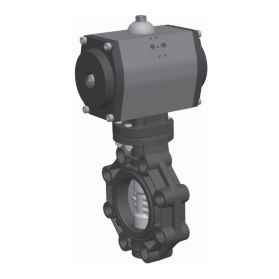
- Page 1 EXTREME BUTTERFLY VALVES Pneumatic actuator 0045 INSTALLATION AND MAINTENANCE MANUAL PVC-U (EPDM/FPM) CPVC (EPDM/FPM) (EPDM/FPM) PVDF (EPDM/FPM) (EPDM/FPM)
- Page 2 Declaración de conformidad CE / EC Declaration of Conformity El fabricante / manufacturer: CEPEX S.A.U. Avinguda Ramon Ciurans 40 ( Parcel.la 6) - P. I. Congost 08530 LA GARRIGA Declara que nuestras vávulas / declares that our valves: Tipo / Type: Válvulas de Mariposa /...
- Page 3 ENGLISH PAGE 04 ESPAÑOL PAGE 12 FRANÇAIS PAGE 20 PORTUGUÊS PAGE 28 ITALIANO PAGE 36 DEUTSCH PAGE 44...
-
Page 4: General Safety Advice
Correct installation and handling of the valve, as well as adherence to the maximum pressure and temperature conditions specified in this manual are essential in order to preserve the service life of the valve. The liquid to be conduted must be compatible with the valve materials. Consult chemical resistance charts published by Cepex or consult the technical department. - Page 5 ENGLISH INDUSTRIAL PNEUMATIC BUTTERFLY VALVE 1. DEFINITION Butterfly valve for isolating the flow in liquid handling systems. Design based on Standard EN ISO 16136 in accordance with Directive 97/23/EC. The valve is available with PVC-U, CPVC, PP-H, PVDF and ABS discs and EPDM and FPM sealing gaskets. The choice of material for the body and gaskets depends on the type of liquid to be carried and on the working temperature of the liquid, in accordance with the chemical resistance tables available on our website and the pressure/temperature chart in this Manual.
-
Page 6: Butterfly Valve
INDUSTRIAL PNEUMATIC BUTTERFLY VALVE ENGLISH 3. BUTTERFLY VALVE 3.1 VERICATION OF VALVE TYPE On opening the packaging please check that the valve is the model ordered. Check that the actuator model corresponds with the code number ordered. Kv / % opening (G 3.2) Make especially sure that the voltage indicated on the actuator label corresponds to that of your mains supply (actuators do no Flow / valve opening... - Page 7 ENGLISH INDUSTRIAL PNEUMATIC BUTTERFLY VALVE 4. DIMENSIONS Fig.3 T4.1 (mm) HOLES 125-145 150-170 180-192 190-215 270-298 329-355 384-427 See the actuator and limit switch manuals to check the dimensions D, E and G. Fig.4 Actuation coupling dimensions (T 4.2) ISO FLANGE SQUARE (mm) 14 / 17 14 / 17...
-
Page 8: Installation And Comissioning
For solvent or welded connections, ensure also that the parts to be connected are of the same material and that the correct solvent or welding tools are used. To install the valve, follow best installation practice recommendations provided on the Cepex website, paying specific attention to thermal expansion and pipe alignment. -
Page 9: Solenoid Valve
In the case of a spring return actuator, Cepex will normally serve the closed valve as standard. 6.2 SPRING RETURN NORMALLY OPEN VALVE (Fig. 9) The valve is opened without an air supply. - Page 10 INDUSTRIAL PNEUMATIC BUTTERFLY VALVE ENGLISH 7. OPERATION AND MAINTENANCE INSTRUCTIONS It is recommended that the condition of the sealing gasket be regularly checked, since it may show signs of mechanical wear due to pressure, handling and contact with the liquid. The sealing gasket should be greased in the disc contact area (the grease must be compatible with the materials of the gasket and the disc).
-
Page 11: Troubleshooting
ENGLISH INDUSTRIAL PNEUMATIC BUTTERFLY VALVE 10. TROUBLESHOOTING FAULT POSSIBLE CAUSE FAULT CLEARANCE The disc does not fully open The sockets were not correctly Disassemble the valve and bevel the or close. bevelled. sockets as indicated in table T5.2. Foreign materials in the compart- Disassemble the valve and check for ment (adhesive, etc.). -
Page 12: Recomendaciones Generales De Seguridad
El líquido conducido debe ser compatible con los materiales de la válvula. Consultar la tabla de resistencia química publicado en la website de Cepex o consultar con el departamento técnico. No es recomendado el uso de herramientas para abrir o cerrar el control manual de la válvula. - Page 13 ESPAÑOL VÁLVULA DE MARIPOSA INDUSTRIAL NEUMÁTICA 1. DEFINICIÓN Válvula de mariposa para interrumpir el paso del flujo en sistemas de conducción de fluidos. El líquido puede circular en ambas direcciones. Diseño basado en EN ISO 16136 Standard de acuerdo con 97/23/EC Directive. La válvula está...
- Page 14 VÁLVULA DE MARIPOSA INDUSTRIAL NEUMÁTICA ESPAÑOL 3. VÁLVULA DE MARIPOSA Kv / % apertura (G 3.2) Flow / valve opening 3.1 VERIFICACIÓN DEL TIPO DE VÁLVULA Caudal / Apertura Al abrir el embalaje, comprobar que la válvula es el modelo que usted pidió. Comprobar que el modelo del actuador corresponde con el código pedido.
- Page 15 ESPAÑOL VÁLVULA DE MARIPOSA INDUSTRIAL NEUMÁTICA 4. DIMENSIONES Fig.3 T4.1 (mm) HOLES 125-145 150-170 180-192 190-215 270-298 329-355 384-427 Ver el manual del actuador para las dimensiones D, E y G. Fig.4 Dimensiones de acople del actuador (T 4.2) ISO FLANGE SQUARE (mm) 14 / 17 14 / 17...
-
Page 16: Instalación
Para unones encoladas o soldadas, asegurarse también que las partes a conectar son del mismo material y que está usando el adhesivo o herramientas de soldar correctos. Para instalar la válvula, seguir las recomendaciones de instalación correcta proporcionadas en la website de Cepex, prestando particular atención a la expansión termal y alineación de tubería. - Page 17 En el caso del actuador de simple efecto, Cepex lo servirá normalmente cerrado como estandard. 6.2 SIMPLE EFECTO NORMALMENTE ABIERTO (Fig. 10) Fig.
- Page 18 VÁLVULA DE MARIPOSA INDUSTRIAL NEUMÁTICA ESPAÑOL 7. OPERACIÓN E INSTRUCCIONES DE MANTENIMIENTO Se recomienda comprobar regularmente la condición de la junta del cuerpo, ya que puede mostrar signos de fatiga mecánica debido a la presión o al contacto con el líquido. La junta del cuerpo debe ser engrasada en el área de contacto con la compuerta (la grasa debe ser compatible con los materiales de la junta y de la compuerta).
-
Page 19: Solución De Problemas
ESPAÑOL VÁLVULA DE MARIPOSA INDUSTRIAL NEUMÁTICA 10. SOLUCIÓN DE PROBLEMAS PROBLEMA POSIBLE CAUSA SOLUCIÓN La compuerta no abre o cierra Los manguitos no han sid correcta- Desmontar la válvula y chaflanar los man- completamente. mente chaflanados. guitos como se indica en la tabla T5.2. Materiales extraños en el comparti- Demontar la válvula y comprobar si hay mento (adhesivo, etc.). -
Page 20: Consignes Generales De Securite
Liquide à transporter doit être compatible avec les matériels du robinet. Consultez les diagrammes de résistance aux produits chimiques publiés par Cepex ou contactez le service technique. L’usage des outils pour ouvrir ou fermer le robinet de commande manuelle n’est pas recommandé. - Page 21 FRANÇAIS VANNE PAPILLON PNEUMATIQUE INDUSTRIAL 1. DEFINITION Vanne à papillon pour l’isolation du flux dans les systèmes de manutention des liquides. Conçu suivant la norme EN ISO 16136 conformément à la Directive 97/23/EC. La vanne est disponible avec des papillons en PVC-U, CPV-C, PP-H, PVDF, ABS ainsi que des joints d’étanchéité en EPDM perox. et FPM.
- Page 22 VANNE PAPILLON PNEUMATIQUE INDUSTRIAL FRANÇAIS 3. VANNE PAPILLON 3.1 VÉRIFICATION DU TYPE DE ROBINET Lors de l’ouverture de l’emballage, veuillez-vous assurer que le robinet est le modèle Kv / % opening (G 3.2) commandé. Assurez-vous que le modèle de l’actionneur correspond au numéro de code commandé. Flow / valve opening Assurez-vous surtout que la tension indiquée sur l’étiquette de l’actionneur correspond Caudal / Apertura...
- Page 23 FRANÇAIS VANNE PAPILLON PNEUMATIQUE INDUSTRIAL 4. DIMENSIONS Fig.3 T4.1 (mm) HOLES 125-145 150-170 180-192 190-215 270-298 329-355 384-427 Consultez les manuels de l’actionneur et de l’interrupteur de fin de course afin de vérifier les dimensions D, E et G. Fig.4 Dimensions fixation (T 4.2) ISO FLANGE SQUARE (mm)
-
Page 24: Installation Et Mise En Service
Pour les assemblages soudées ou aux solvants, assurez-vous que les pièces à connecter sont du même matériau et que le solvant ou les outils appropriés pour souder sont utilisés. Afin d’installer la vanne, suivez les meilleures recommandations pratiques d’installation sur le site internet de Cepex en portant une attention particulière à l’expansion thermique et l’alignement du tuyau. - Page 25 électrique doit être maintenu pendant la durée de temps au cours duquel le robinet doit rester ouvert. S’il s’agit d’un actionneur à rappel par ressort, Cepex vous fournira normalement le robinet fermé en guise de norme. 6.2 ROBINET NORMALEMENT OUVERTE À SIMPLE EFFET (Fig. 10) Fig.
- Page 26 VANNE PAPILLON PNEUMATIQUE INDUSTRIAL FRANÇAIS 7. INSTRUCTIONS RELATIVES AU FONCTIONNEMENT ET A LA MAINTENANCE Il est recommandé que l’état du joint d’étanchéité soit régulièrement vérifié dans la mesure où il peut présenter des signes d’usures mécaniques causées par la pression, la manipulation et le contact avec le liquide. Le joint d’étanchéité doit être graissé au niveau des zones de contact avec le disque (la graisse doit être compatible avec les matériaux du joint et du disque).
-
Page 27: Dépannage
FRANÇAIS VANNE PAPILLON PNEUMATIQUE INDUSTRIAL 10. DÉPANNAGE PANNE CAUSE PROBABLE REPARATION DE LA PANNE Le disque ne s’ouvre pas ou ne se Les raccordements n’ont pas été Démontez la vanne et biseautez les raccor- ferme pas complètement. correctement biseautés. dements comme indiqués dans le tableau T5.2. -
Page 28: Recomendações Gerais De Segurança
O líquido conduzido deve ser compatível com os materiais da válvula. Consulte a tabela de resistência química publicada no site da Cepex ou consultar o departamento técnico. Não é recomendado a utilização de ferramentas para abrir ou fechar a válvula de controlo manual. - Page 29 PORTUGUÊS VÁLVULA DE BORBOLETA PNEUMATICA INDUSTRIAL 1. DESCRIÇÃO Válvula de borboleta para interromper a passagem de fluxo em sistemas de condutas de líquidos. Design com base na EN ISO 16136 Standard de acordo com 97/23 / Diretiva CE. La comporta da válvula está disponível em PVC-U, CPVC, PP-H, PVDF, ABS e as juntas em EPDM perox. e FPM. A escolha do material do corpo e das juntas depende do tipo de líquido a transportar e a temperatura do líquido, de acordo com os gráficos de resistência química disponíveis no nosso site e os gráficos pressão / temperatura neste manual.
- Page 30 VÁLVULA DE BORBOLETA PNEUMATICA INDUSTRIAL PORTUGUÊS 3. VÁLVULA BORBOLETA 3.1 VERIFICAÇÃO DO TIPO DE VÁLVULA Kv / % opening (G 3.2) Ao abrir a embalagem, verifique que a válvula é do modelo que pediu. Verifique se o modelo do actuador corresponde com o código de pedido. Preste especial Flow / valve opening Caudal / Apertura atenção para a corrente (voltagem) indicada na etiqueta do actuador se corresponde ao...
- Page 31 PORTUGUÊS VÁLVULA DE BORBOLETA PNEUMATICA INDUSTRIAL 4. DIMENSÕES Fig.3 T4.1 (mm) HOLES 125-145 150-170 180-192 190-215 270-298 329-355 384-427 Consulte o manual do actuador para as dimensões D, E e G. Fig.4 Dimensões união (T 4.2) ISO FLANGE SQUARE (mm) 14 / 17 14 / 17 14 / 17...
- Page 32 Para juntas coladas ou soldadas deverá assegurar também que as partes a ligar são do mesmo material e deverá certificar-se se está a utilizar o adesivo ou as ferramentas de soldadura correctas. Para instalar a válvula, siga as instruções de instalação correta no site da Cepex, prestando especial atenção à expansão térmica e ao alinhamento da tubagem.
- Page 33 No caso do actuador de efeito simples, Cepex enviá-lo-á normalmente fechado como standard. 6.2 EFEITO SIMPLES NORMALMENTE ABERTO (Fig. 10) Fig.
- Page 34 VÁLVULA DE BORBOLETA PNEUMATICA INDUSTRIAL PORTUGUÊS 7. FUNCIONAMENTO E INSTRUÇÕES DE MANUTENÇÃO Recomenda-se verificar regularmente o estado da junta da válvula, uma vez que pode mostrar sinais de stress mecânico, devido à pressão ou contacto com o líquido. A junta da válvula deve ser lubrificada na área de contacto com a comporta (o lubrificante deve ser compatível com materiais os materiais da junta e da comporta).
-
Page 35: Solução De Problemas
PORTUGUÊS VÁLVULA DE BORBOLETA PNEUMATICA INDUSTRIAL 10. SOLUÇÃO DE PROBLEMAS PROBLEMA CAUSA POSSÍVEL SOLUÇÃO A comporta não abre ou fecha As arestas das braçadeiras não foram Desmontar a válvula e recortar as completamente. cortadas correctamente. braçadeiras em forma de meia-lua como mostra a tabela T5.2. - Page 36 Il liquido convogliato deve essere compatibile con i materiali della valvola. Consultare la tabella di resistenza chimica pubblicata nel sito di Cepex o contattare l’ufficio tecnico. Non è consigliabile l’uso di strumenti per l’apertura e la chiusura del controllo manuale della valvola.
- Page 37 ITALIANO VALVOLA A FARFALLA PNEUMATICA INDUSTRIAL 1. DEFINIZIONE Valvola a farfalla per l’interruzione del flusso in sistemi per la conduzione di fluidi. Progettazione basata sulla norma EN ISO 16136 ai sensi della Direttiva 97/23/CE. La valvola è disponibile con lente in PVC-U, CPVC, PP-H, PVDF, ABS e giunti in EPDM perox. e FPM. La scelta del materiale del corpo e dei giunti dipende dal tipo di liquido da trasportare e dalla temperatura di funzionamento del liquido, secondo le tabelle di resistenza chimica disponibili nel nostro sito web e i grafici di pressione/temperatura inclusi nel presente manuale.
-
Page 38: Garanzia
VALVOLA A FARFALLA PNEUMATICA INDUSTRIAL ITALIANO 3. VALVOLA A SFERA Kv / % opening (G 3.2) 3.1 VERIFICA DEL TIPO DI VALVOLA All’apertura della confezione, verificare che la valvola corrisponda al modello richiesto. Flow / valve opening Verificare che il modello dell’attuatore corrisponda al codice richiesto. Prestare particolarmente Caudal / Apertura attenzione al voltaggio indicato sull’etichetta dell’attuatore, che deve corrispondere a quello dell’alimentazione elettrica (un voltaggio errato può... - Page 39 ITALIANO VALVOLA A FARFALLA PNEUMATICA INDUSTRIAL 4. DIMENSIONI Fig.3 T4.1 (mm) HOLES 125-145 150-170 180-192 190-215 270-298 329-355 384-427 Vedere il manuale dell’attuatore per le dimensioni D, E e G. Fig.4 Dimensioni unioni (T 4.2) ISO FLANGE SQUARE (mm) 14 / 17 14 / 17 14 / 17 14 / 17...
-
Page 40: Installazione
Per collegamenti incollati o saldati, assicurarsi anche che le parti da collegare siano dello stesso materiale e di utilizzare l’adesivo e gli strumenti corretti per la saldatura. Per installare la valvola, attenersi alle raccomandazioni per la corretta installazione fornite nel sito web di Cepex, prestando una particolare attenzione alla dilatazione termica e all’allineamento della tubatura. - Page 41 Nel caso dell’attuatore a semplice effetto, Cepex lo fornisce normalmente chiuso. 6.2 SEMPLICE EFFETTO NORMALMENTE APERTO (Fig. 10) In assenza d’aria la valvola rimane aperta.
- Page 42 VALVOLA A FARFALLA PNEUMATICA INDUSTRIAL ITALIANO 7. OPERAZIONE E ISTRUZIONI DI MANUTENZIONE E’ consigliabile controllare regolarmente lo stato del giunto del corpo, che può mostrare segni di fatica meccanica a causa della pressione o del contatto con il liquido. Il giunto del corpo deve essere lubrificato nell’area di contatto con la saracinesca (il grasso deve essere compatibile con i materiali del giunto e della saracinesca).
-
Page 43: Soluzione Di Eventuali Problemi
ITALIANO VALVOLA A FARFALLA PNEUMATICA INDUSTRIAL 10. SOLUZIONE DI EVENTUALI PROBLEMI POSSIBILE PROBLEMA CAUSA SOLUZIONE La saracinesca non si apre o chiude I manicotti non sono stati smussati Smontare la valvola e smussare i manicotti completamente. in modo corretto. come indicato nella tabella T5.2. Materiali estranei nel compartimen- Smontare la valvola e verificare che non to (adesivo, etc.). -
Page 44: Allgemeine Sicherheitshinweise
Die geführte Flüssigkeit muss mit allen Materialien des Ventils kompatibel sein. Sehen Sie in der Tabelle für Chemikalienbeständigkeit nach, die auf der Webseite von Cepex verfügbar ist, oder wenden Sie sich an die technische Abteilung. Der Einsatz von Werkzeugen zum Öffnen oder Schließen der manuellen Ventilsteuerung wird nicht empfohlen. - Page 45 DEUTSCH PNEUMATISCH ABSERRKLAPPE INDUSTRIAL 1. DEFINITION Absperrklappen zur Unterbrechung des Medienstroms in einem System zur Handhabung von Flüssigkeiten. Das Design basiert auf der Norm EN ISO 16136, gemäß der Richtlinie 97/23/EC. Das Ventil ist mit einem Klappen aus PVC-U, CPVC, PP-H, PVDF, ABS und Dichtungen aus EPDM perox. und FPM verfügbar. Die Auswahl des Materials des Körpers und der Dichtungen ist von der zu transportierenden Flüssigkeit sowie von der Arbeitstemperatur der Flüssigkeit abhängig, gemäß...
- Page 46 PNEUMATISCH ABSERRKLAPPE INDUSTRIAL DEUTSCH 3. ABSPERRKLAPPE 3.1 ÜBERPRÜFUNG DES VENTILTYPS Kv / % opening (G 3.2) Öffnen Sie die Verpackung und überprüfen Sie, ob das Ventil dem von Ihnen bestellten Modell entspricht. Überprüfen Sie, ob der Code des Antriebs dem bestellten Modell entspricht. Achten Sie Flow / valve opening Caudal / Apertura insbesondere darauf, ob die auf dem Etikett des Antriebs angegebene Spannung Ihrer...
- Page 47 DEUTSCH PNEUMATISCH ABSERRKLAPPE INDUSTRIAL 4. DIMENSIONS Fig.3 T4.1 (mm) HOLES 125-145 150-170 180-192 190-215 270-298 329-355 384-427 Siehe Betriebsanleitung des Antriebs für die Abmessungen D, E und G. Fig.4 ABMESSUNGEN (T 4.2) ISO FLANGE SQUARE (mm) 14 / 17 14 / 17 14 / 17 14 / 17 17 / 22...
-
Page 48: Installation
Klebemittel oder die richtigen Schweißwerkzeuge nutzen. Zur Installation des Ventils befolgen Sie bitte die Hinweise für eine korrekte Installation, die auf der Webseite von Cepex zur Verfügung stehen. Achten Sie insbesondere auf die thermische Ausdehnung und die Ausrichtung der Rohre. - Page 49 Weise wird es bereits im Werk installiert (NAMUR VDE/VDI 3845 Standard). 6.6 AUSTRITTSREGULATOR Cepex empfiehlt stark, Austrittsregler zu installieren, um die Geschwindigkeit zu steuern, mit der der Antrieb das Ventil öffnet, um so Wasserschläge zu verhindern. Im Austrittsregler kann ein Schalldämpfer inkludiert werden.
-
Page 50: Austausch Der Dichtung
PNEUMATISCH ABSERRKLAPPE INDUSTRIAL DEUTSCH 7. BETRIEB UND WARTUNGSHINWEISE Es wird empfohlen, dass der Zustand der Dichtungen regelmäßig überprüft wird, da es aufgrund des Drucks oder des Kontakts mit der Flüssigkeit zu mechanischem Verschleiß kommen kann. Die Dichtung muss im Kontaktbereich mit der Scheibe eingefettet werden (das Schmiermittel muss mit den Materialien der Dichtung und der Scheibe kompatibel sein). -
Page 51: Problemlösung
DEUTSCH PNEUMATISCH ABSERRKLAPPE INDUSTRIAL 10. PROBLEMLÖSUNG PROBLEM MÖGLICHE URSACHE LÖSUNG Die Scheibe öffnet oder schließt sich Die Muffen wurden nicht korrekt Bauen Sie das Ventil aus und fasen Sie nicht vollständig. angefast. die Muffen gemäß Tabelle T5.2 an. Fremdkörper im Inneren (Klebemit- Bauen Sie das Ventil aus und überprüfen tel etc.). - Page 52 Av. Ramón Ciurans 40, PI Congost P6 La Garriga (BCN) - Spain Tel: +34 93 870 42 08 www.cepex.com cepex@cepex.com CODE: C584075MNXT - VERSION: 2.1 - DATE: 17/10/2019 COPYRIGHT © CEPEX, S.A.U. - ALL RIGHTS RESERVED...
Need help?
Do you have a question about the Extreme BTV-PVC-U-PA and is the answer not in the manual?
Questions and answers