Table of Contents
Advertisement
Quick Links
GETTING STARTED GUIDE
PXIe-5830
12 GHz, 1 GHz Bandwidth PXI Vector Signal Transceiver
Note
Before you begin, install and configure your chassis and controller.
This document explains how to install, configure, and test the PXIe-5830. The PXIe-5830 is
an RF vector signal transceiver (VST). You can program the PXIe-5830 instrument using
RFmx or NI-RFSA and NI-RFSG driver software.
The PXIe-5830 instrument configuration comprises the following modules:
•
PXIe-5820 Vector Signal Transceiver
•
PXIe-3621 Vector Signal Up/Down Converter
There is no single instrument labeled "PXIe-5830."
Contents
Verifying the System Requirements..........................................................................................2
Unpacking the Kit..................................................................................................................... 2
Verifying the Kit Contents................................................................................................ 3
Preparing the Environment....................................................................................................... 4
Choosing and Installing the Software....................................................................................... 5
Software Options...............................................................................................................5
Installing the Software...................................................................................................... 5
Installing the PXIe-5830........................................................................................................... 6
Interconnecting the PXIe-5830 Modules.......................................................................... 8
Direct Connections to the PXIe-5830..................................................................................... 10
Configuring the PXIe-5830 in MAX...................................................................................... 10
Self-Calibration....................................................................................................................... 11
Performing a Self-Calibration Using NI-RFSA..............................................................12
Locating the Software and Examples......................................................................................13
Software Locations......................................................................................................... 13
Programming Examples Locations................................................................................. 15
Making a First Measurement.................................................................................................. 16
Troubleshooting...................................................................................................................... 17
What Should I Do if the PXIe-3621 Does Not Appear in MAX?.................................. 17
Why Is the ACCESS LED Off When the Chassis Is On?...............................................17
What Should I Do if the PXIe-5830 Fails the Self-Test?................................................18
What Should I Do if the Instrument Does Not Initialize?...............................................18
Advertisement
Table of Contents

Subscribe to Our Youtube Channel
Related Manuals for National Instruments PXIe-5830


Summary of Contents for National Instruments PXIe-5830
-
Page 1: Table Of Contents
Note Before you begin, install and configure your chassis and controller. This document explains how to install, configure, and test the PXIe-5830. The PXIe-5830 is an RF vector signal transceiver (VST). You can program the PXIe-5830 instrument using RFmx or NI-RFSA and NI-RFSG driver software. -
Page 2: Verifying The System Requirements
NI Services..........................25 Verifying the System Requirements To use the PXIe-5830, your system must meet certain requirements. For more information about minimum system requirements, recommended system, and supported application development environments (ADEs), refer to the readme, which is installed or available at ni.com/manuals. -
Page 3: Verifying The Kit Contents
Do not grasp or pull on non-metallic portions of the cables. Other Equipment There are required items not included in your kit that you need to install or operate the PXIe-5830. Your application may require additional items not included in your kit to install or operate your hardware. Required Items •... -
Page 4: Preparing The Environment
Preparing the Environment Ensure that the environment you are using the PXIe-5830 in meets the following specifications. Operating ambient temperature 0 °C to 45 °C Operating relative humidity 10% to 90%, noncondensing (IEC 60068-2-56) Maximum altitude 2,000 m (800 mbar) (at 25 °C ambient... -
Page 5: Choosing And Installing The Software
Choosing and Installing the Software Software Options NI provides three software options for programming the PXIe-5830—RFmx, NI-RFSA and NI-RFSG instrument driver software. Table 1. PXIe-5830 Software Options Software Description Use Case Option RFmx Provides a single-handle instrument Use RFmx SpecAn to perform spectral driver with built-in measurements. -
Page 6: Installing The Pxie-5830
5. PXI Express Peripheral Slot 3. PXI Express Hybrid Peripheral Slot The modules that comprise the PXIe-5830 can be placed in PXI Express peripheral slots, PXI Express hybrid peripheral slots, or PXI Express system timing slots. 6 | ni.com | PXIe-5830 Getting Started Guide... - Page 7 Note For more information about installing slot blockers and filler panels, go to ni.com/r/pxiblocker. 12. Power on the chassis. Related Information Installing the Software on page 5 PXIe-5830 Getting Started Guide | © National Instruments Corporation | 7...
-
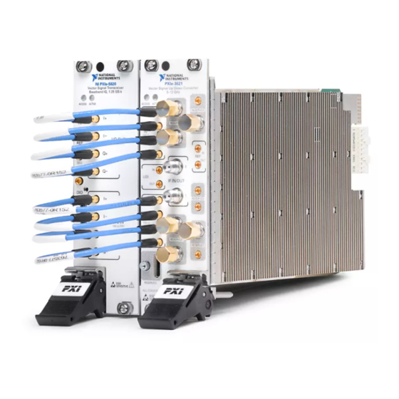
Page 8: Interconnecting The Pxie-5830 Modules
Incorrect torque at SMA connections can damage device connectors and degrade signal fidelity. Connecting the PXIe-5820 and PXIe-3621 Complete the following steps for the baseband signal connections and Reference Clock connection, as shown in the following figure. 8 | ni.com | PXIe-5830 Getting Started Guide... - Page 9 I/Q OUT I- I/Q IN I- I/Q OUT Q+ I/Q IN Q+ I/Q OUT Q- I/Q IN Q- I/Q IN I+ I/Q OUT I+ I/Q IN I- I/Q OUT I- PXIe-5830 Getting Started Guide | © National Instruments Corporation | 9...
-
Page 10: Direct Connections To The Pxie-5830
This completes the Reference Clock connection. Direct Connections to the PXIe-5830 The PXIe-5830 is a precision RF instrument that is sensitive to ESD and transients. Ensure you are making proper direct connections to the PXIe-5830 to avoid damaging the hardware. -
Page 11: Self-Calibration
Self-test the hardware by selecting the item in the configuration tree and clicking Self- Test in the MAX toolbar. Repeat this step for all modules in your PXIe-5830 system. The MAX self-test performs a basic verification of hardware resources. -
Page 12: Performing A Self-Calibration Using Ni-Rfsa
Select the device identifier assigned to the PXIe-3621 in MAX in the [Resource Name] drop-down menu. Set Clock Source to OnboardClock. Set Self Calibration Step Operations to Perform All Self Calibration Steps. Run the VI. 12 | ni.com | PXIe-5830 Getting Started Guide... -
Page 13: Locating The Software And Examples
Windows 10 (32-bit)/8.1 (32-bit)/7 (32-bit)- Program Files\National Instruments • Windows 10 (64-bit)/8.1 (64-bit)/7 (64-bit)- Program Files (x86)\National Instruments Microsoft .NET For the location of .NET class libraries, refer to the installed RFmx readme. PXIe-5830 Getting Started Guide | © National Instruments Corporation | 13... - Page 14 Table 3. Location of PXIe-5830 Software Options (Continued) Software Location Option NI-RFSA LabVIEW Available on the LabVIEW Functions palette at Measurement I/O»NI-RFSA. LabWindows/CVI Available in the \Drivers\niRFSA <IVIROOTDIR32> directory, where is one of the <IVIROOTDIR32> following locations: • Windows 10 (32-bit)/8.1 (32-bit)/7 (32-bit)- Program Files\IVI Foundation\IVI •...
-
Page 15: Programming Examples Locations
If you are using RFmx, NI-RFSA, or NI-RFSG with LabVIEW or LabWindows/CVI, use the NI Example Finder to locate programming examples. Launch LabVIEW or LabWindows/CVI. Select Help»Find Examples to open the NI Example Finder. PXIe-5830 Getting Started Guide | © National Instruments Corporation | 15... -
Page 16: Making A First Measurement
You can verify proper installation and configuration of your instrument by making a measurement using the NI-RFSG and RFmx Soft Front Panels (SFPs). Connect the PXIe-5830 IF IN/OUT 0 and IF IN/OUT 1 ports as appropriate for your application. Select Start»All Programs»National Instruments»NI-RFSG»NI-RFSG Soft Front Panel to launch the NI-RFSG SFP. -
Page 17: Troubleshooting
Apply external signals only while the hardware is powered on. Applying external signals while the hardware is powered off may cause damage. Disconnect any signals from the PXI Express module front panel. PXIe-5830 Getting Started Guide | © National Instruments Corporation | 17... -
Page 18: What Should I Do If The Pxie-5830 Fails The Self-Test
What Should I Do if the Instrument Does Not Initialize? Failure to initialize may indicate a problem with module interconnections or with MAX. If the niRFSA Initialize VI or niRFSG Initialize VI returns an error and the PXIe-5830 fails to initialize, complete the following steps: Reconnect the PXIe-5830 front panel cables securely. -
Page 19: Hardware Connectors And Indicators
Input connector that allows for the use of an external 10 MHz MMPX (f) Reference Clock. REF OUT Output connector that can export a 10 MHz Reference Clock. MMPX (f) PXIe-5830 Getting Started Guide | © National Instruments Corporation | 19... - Page 20 MMPX (f) I/Q IN Input connector for I+ signals. MMPX (f) Input connector for I- signals. MMPX (f) Input connector for Q+ signals. MMPX (f) Input connector for Q- signals. MMPX (f) 20 | ni.com | PXIe-5830 Getting Started Guide...
- Page 21 The indicators are listed in increasing order of priority. For example, if you are generating a waveform using NI-RFSG and waiting on an acquisition Reference Trigger in NI-RFSA, the LED is dim amber. PXIe-5830 Getting Started Guide | © National Instruments Corporation | 21...
- Page 22 MGT REF– / DIO 1 DIO 3 MGT Rx+ 2 MGT Tx+ 2 MGT Rx– 2 MGT Tx– 2 MGT Rx+ 3 MGT Tx+ 3 MGT Rx– 3 MGT Tx– 3 5.0 V Reserved 22 | ni.com | PXIe-5830 Getting Started Guide...
-
Page 23: Pxie-3621 Front Panel And Leds
I/Q IN Input connector for I+ signals. MMPX (f) Input connector for I- signals. MMPX (f) Input connector for Q+ signals. MMPX (f) Input connector for Q- signals. MMPX (f) PXIe-5830 Getting Started Guide | © National Instruments Corporation | 23... - Page 24 OUT Output connector for the Reference Clock. MMPX (f) RESERVED Reserved connectors are not enabled for use on the — PXIe-5830 and should remain capped with 50 Ω terminators to ensure specified instrument performance. 24 | ni.com | PXIe-5830 Getting Started Guide...
-
Page 25: Ni Services
NI product. Product registration facilitates technical support and ensures that you receive important information updates from NI. NI corporate headquarters is located at 11500 N Mopac Expwy, Austin, TX, 78759-3504, USA. PXIe-5830 Getting Started Guide | © National Instruments Corporation | 25... - Page 26 NI trademarks. Other product and company names mentioned herein are trademarks or trade names of their respective companies. For patents covering NI products/technology, refer to the appropriate location: Help»Patents in your software, the file on your media, or the National Instruments Patent Notice at . You can find patents.txt ni.com/patents...
Need help?
Do you have a question about the PXIe-5830 and is the answer not in the manual?
Questions and answers