Table of Contents
Advertisement
Quick Links
LPRT 517914
by
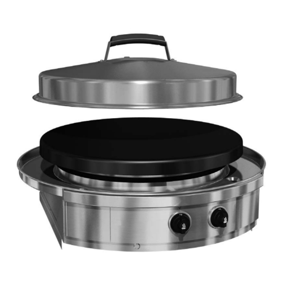
AGA Professional Series Outdoor Gas Grills
25G drop in cooktop
For Outdoor Use Only.
Do Not Use Indoors.
Installations & Operation Instructions
CAUTION: THIS UNIT IS HEAVY, PROPER EQUIPMENT AND ADEQUATE MANPOWER MUST BE USED IN MOVING THE
RANGE TO AVOID DAMAGE TO THE UNIT OR THE FLOOR.
REMEMBER, when replacing a part on this appliance, use only spare parts that you can be assured conform to the safety and
performance specification that we require.
DO NOT use reconditioned or copy parts that have not been clearly authorised by AGA.
PLEASE READ THESE INSTRUCTIONS BEFORE USING THIS APPLIANCE
AND KEEP IN A SAFE PLACE FOR FUTURE REFERENCE.
For use in GB and IE
05/2021 EINS 517915
Advertisement
Table of Contents

Subscribe to Our Youtube Channel
Related Manuals for Evo AGA AGA-10-0096-LP-CE


Summary of Contents for Evo AGA AGA-10-0096-LP-CE
- Page 1 LPRT 517914 AGA Professional Series Outdoor Gas Grills 25G drop in cooktop For Outdoor Use Only. Do Not Use Indoors. Installations & Operation Instructions CAUTION: THIS UNIT IS HEAVY, PROPER EQUIPMENT AND ADEQUATE MANPOWER MUST BE USED IN MOVING THE RANGE TO AVOID DAMAGE TO THE UNIT OR THE FLOOR.
- Page 2 Useful Information What is not covered by this warranty: It maybe useful to make a note of your AGA appliance Serial Number when it is being installed. Conditions and damages resulting from any of the The serial number can be found on the right hand side of the following: control panel.
- Page 3 My AGA Details: Model Nos: AGA Professional Series Gas Grill 25G drop in AGA-10-0096-LP-CE Serial No: AGA Service No: AGA Dealer or store contact No: Date of Installation:...
-
Page 4: Table Of Contents
Contents General Warnings Outdoor use advice Unpacking Clearance dimensions Countertop Installation (1 of 4) Countertop Installation (2 of 4) Countertop Installation (3 of 4) Countertop Installation (4 of 4) Fitting chassis in counter top Drip pan installation Drip pan and gasket installation Assembling cook surface retaining fasteners 10. -
Page 5: General Warnings
General Warnings FOR YOUR SAFETY FOR YOUR SAFETY If You Smell Gas: Do not store or use gasoline or other Shut off gas to appliance. flammable vapours and liquids in the vicinity of this or any other appliance. Extinguish any open flame. An LP Tank not connected for use shall not Remove grill cooking surface. -
Page 6: Outdoor Use Advice
Outdoor use advice This appliance shall only be used in an above ground open-air situation with natural ventilation, without stagnant areas, where gas leakage and products of combustion are rapidly dispersed by wind and natural convection. Any enclosure in which the appliance is used shall comply with one of the following: •... - Page 7 READ FIRST IMPORTANT PRODUCT AND SAFETY INFORMATION Installation Requirements CAUTION ALWAYS KEEP ANY AND ALL FLAMMABLE LIQUIDS AND COMBUSTIBLE MATERIALS THIS APPLIANCE MUST ONLY BE INSTALLED BY PERSONS AWAY FROM UNIT. DO NOT STORE TOWELS OR THAT ARE CERTIFIED TO LOCAL REGULATIONS. UTENSILS, OR ANY OTHER ITEMS ON UNIT’S This AGA is suitable for Propane only, and cannot be used on DRIP PAN.
-
Page 8: Unpacking
Unpacking 3/8” 228mm 25” 635mm Diameter 19 7/8” 503mm 32” 816mm Cooking Surface: Lift and separate cooking surface from unit and place next to installation area. Drip Pan Gasket: The cooking surface is heavy. Gasket is secured Use caution when lifting. to top of drip tray. -
Page 9: Clearance Dimensions
Clearance dimensions 305mm (12”) clearance from 915mm (36”) clearance from cooking surface cooking surface to to combustible ceiling materials. combustible back 305mm (12”) clearance wall materials. from cooking surface to combustible sidewall materials. If installing alongside another 25G unit, provide 50mm (2”) minimum clearance from edge of drip pans. -
Page 10: Countertop Installation (1 Of 4)
Countertop Installation (1 of 4) Countertop TOP VIEW with substrate underlayment Cabinetry box: 1-1/2” below countertop surface 12" 305mm Countertop overhang to cabinet front NOTE: If the dimensions for the countertop overhang and countertop depth cutout are not followed, there will 12"... -
Page 11: Countertop Installation (2 Of 4)
Countertop Installation (2 of 4) Black o-ring under drip pan bead CORRECT ALIGNMENT OF DRIP PAN AND INCORRECT ALIGNMENT OF DRIP PAN AND CHASSIS TO COUNTERTOP CHASSIS TO COUNTERTOP Possible reasons for incorrect alignment: Top of cabinetry box is less than 3 cm from countertop Chassis mounting brackets are too high. -
Page 12: Countertop Installation (3 Of 4)
Countertop Installation (3 of 4) SIDE VIEW 572mm 22 1 " Finished cabinet face set back from finished countertop front edge 146mm 68mm 2 11 " " Metal Right 146mm 146mm Angle Mounting " " Brackets (supplied) Shelving or drawers can be installed under AGA 25G if desired. -
Page 13: Countertop Installation (4 Of 4)
Brackets are slotted for fasteners at each four corners. Shelving or drawers can be installed under AGA 25G if desired. Step. 3: Construct a bay for the Evo unit with your chosen cabinet system. Position and fasten the supplied mounting brackets 195mm (7-21/32”) below the finished countertop surface. -
Page 14: Fitting Chassis In Counter Top
Fitting chassis in counter top Use supplied 1/4” fasteners to bolt chassis to angle brackets. Step. 4 Slide the AGA 25G chassis into the counter top so it rests on top of the installed brackets. Bolt unit to angle brackets using supplied 1/4”... -
Page 15: Drip Pan Installation
Drip pan installation Drip Tray Catches GRILL FRONT Step. 5 Slide drip tray over chassis circular skirt positioning spillover slots to the corresponding slots of the top chassis deck. Notice the drip pan catches showing through the inside cutout locations of the circular chassis skirt. From the inside of the skirt, use each of the three latches to pull the drip pan down into the counter. -
Page 16: Drip Pan And Gasket Installation
Drip pan and gasket installation Use No. 3 Phillips screwdriver to secure drip pan at the access points. Drip pan gasket seam at rear CROSS SECTION OF CROSS SECTION OF CROSS SECTION OF CHASSIS ACCESS SLOT DRIP PAN TOP DRIP PAN EDGE countertop chassis drip pan... -
Page 17: Assembling Cook Surface Retaining Fasteners
Assembling cook surface retaining fasteners IT IS RECOMMENDED THE COOKING SURFACE BE PLACED ON A PROTECTED WORK SURFACE WITH THE FLANGE FACING UPWARD. Using a 7/16” wrench, tighten the Rear Retaining Bullet to the cooking surface tab with two each 1/4” x 20 hex bolt and locking nut. -
Page 18: Installing Cook Surface (1 Of 3)
10. Installing cook surface (1 of 3) Place suitable protection on drip pan (towel or cardboard). Place cook surface vertically with Bullet Fastener facing downward. Step. 8 Position the cook surface at the rear of the burner chassis by placing the cook surface in the area of the drip pan, separated by a towel or cardboard to prevent damage to the drip pan. -
Page 19: Installing Cook Surface (2 Of 3)
10. Installing cook surface (2 of 3) COOK SURFACE SUPPORT TAB BOTTOM-UP VIEW OF REAR COOK SURFACE REAR BULLET CUT AWAY VIEW OF REAR COOK SURFACE SHOWING BULLET ENGAGED IN CHASSIS SLOT Step. 9 Place cook surface over circular skirt with the three support tabs (located under cook surface) resting on the chassis skirt top. -
Page 20: Installing Cook Surface (3 Of 3)
10. Installing cook surface (3 of 3) J-Hook Guide Tube Open waste doors to locate end of J-hook. Tighten nyloc nut at end of each J-hook. Step. 10 Locate two (2) J-hooks attached to underside of cooktop, cut zip ties and remove nyloc nut. One at a time, slide J-hooks through guide tubes. -
Page 21: Gas Type, Gas Pressure, And Heat Inputs
BE, CH, CZ, ES, FR, GB, GR,HR, 411.4 10.93 kW I3P - 37 mbar IE, IT, LT, NL, PL, PT, SI, SK, TR 362.8 I3P - 50 mbar AT, CH, CZ, DE, NL, SK 9.64 kW Evo America, LLC DU-25G-0100-CE... -
Page 22: Gas Connections
12. Gas Connections Gas Cylinder The AGA 25G gas grill is desgined for use with Quick Connection Cylinder such as the Calor 5kg patio gas with the following dimensions: • 5kg - height 314mm, diameter 306mm. This gas cylinder is designed for use with the 27mm Clip-on type regulator. -
Page 23: Gas Soundness
All factory-made connections have been thoroughly checked for gas leaks. The burners and ignition system has been flame tested. As a safety precaution, we recommend you recheck all fittings for leaks before using your Evo grill. Shipping and handling may loosen or damage a gas fitting. -
Page 24: Gas Burner And Injectors
14. Gas burner and injectors The Affinity 25G Gas Tube Burners are located under the cooking surface and inside the stainless steel Burner Skirt. They are arranged with the smaller inner burner located in the center of the burner skirt and the larger outer burner located outside the inner burner. -
Page 25: Operating Instructions
16. Operating Instructions Please refer to page 22 - page 26 before using this AGA outdoor gas grill... -
Page 26: G Temperature Control
17. 25G Temperature Control Inner Burner and Inner Control Knob - The Inner Gas Inner Burner Outer Burner Burner is a 7.5” (190mm) in diameter. This burner is controlled by the Inner or center control knob. Temperatures are adjustable from Low to High. Starting at the Off position, the Inner Control Knob rotates 180-degrees counterclockwise through three positions. -
Page 27: Lighting Instructions
18. Lighting Instructions BEFORE EACH USE: Inspect gas hose under unit. If it is evident there is excessive abrasion or wear, or the hose is cut, please contact Evo for a replacement hose. Electronic Ignitor Lighting Procedure: Read instructions carefully before lighting. -
Page 28: Checking Operation
19. Checking Operation Any of the following are considered to be abnormal operation and may require servicing: Right Wrong • Excessive yellow tipping of the burner flame (See Flame Flame diagram above). Excessive Yellow Yellow Tip Tipping • Sooting up of cooking utensils. Light Blue Light Blue •... -
Page 29: Removing Spill Trays
20. Removing Spill Trays Spillover Slot Insert each waste pan all the way to the back of the left and Removable waste pan right compartments. Access Door Do not operate cook top or clean drip pan into spillover slots without waste pans installed in spillover doors. -
Page 30: Cooking Surface Maintenance
21. Cooking Surface Maintenance Regular cleaning and care for your AGA 25G cooking surface will keep it looking and functioning its best. The cooking surface is designed to hold a fine layer of cooking oil which will create a ‘seasoning’ on its surface. This seasoning promotes a non-stick surface and is easily maintained. - Page 32 For further advice or information contact your local AGA Specialist. With AGA Rangemaster’s policy of continuous product improvement, the Company reserves the right to change specifications and make modifications to the appliances described and illustrated at any time. AGA Rangemaster Station Road Ketley Telford Shropshire TF1 5AQ...
Need help?
Do you have a question about the AGA AGA-10-0096-LP-CE and is the answer not in the manual?
Questions and answers