Sony ECM-Z37C Service Manual
Hide thumbs
Also See for ECM-Z37C:
- Operating instructions (2 pages) ,
- Operating instructions (4 pages)
Table of Contents
Advertisement
Quick Links
SERVICE MANUAL
Ver 1.0 2001. 02
Ver 1.0 2001. 01
Sony Corporation
9-927-983-11
2001B0400-1
Audio Entertainment Group
© 2001. 2
General Engineering Dept.
SPECIFICATIONS
General
Type
Electret condenser microphone
Microphone cord
1.5 mm dia. single core-shielded, OFC (Oxygen-free copper)
cord with the gold-plated L-shaped miniplug
Length: Approx. 30 cm (11
Approx. 46 × 122 × 36.5 mm (W × H × D)
Dimensions
× 4
× 1
(1
13 /16
7 /8
Mass
Approx. 44 g (1 lb 6 oz) including battery and cord
Supplied accessories Wind screen (1)
Extension arm (1)
Carrying case (1)
Performance
Frequency response
100 - 10,000 Hz
Output impedance
2.2 kilohm ± 30 %
Sensitivity
Open circuit output level*
Power requirements
Lithium battery CR2025
Continuous lasting hours: Approx. 300 hours
Plug-in power
2
Maximum input sound pressure level*
More than 105 dB
Dynamic range
More than 79 dB
Operating temperature range
0°C to 40°C (32°F to 104°F)
*
1
0 dB = 1 v/Pa, 1,000 Hz (1 Pa = 10 µbar = 94 dB
*
2
4 % wave distortion is present at 1,000 Hz
= 2 × 10
(0 dB
Pa)
-5
SPL
Design and specifications are subject to change without notice.
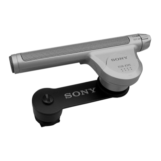
ELECTRET CONDENSER MICROPHONE
ECM-Z37C
7 /8
inches)
7 /16
inches) (without the projecting parts)
1
: – 41 ± 3.5 dB (8.9 mV)
SPL
)
SPL
Notes on chip component replacement
• Never reuse a disconnected chip component.
• Notice that the minus side of a tantalum capacitor may be
damaged by heat.
US Model
Canadian Model
AEP Model
E Model
1
Advertisement
Table of Contents

Related Manuals for Sony ECM-Z37C


Summary of Contents for Sony ECM-Z37C
- Page 1 ECM-Z37C SERVICE MANUAL US Model Canadian Model Ver 1.0 2001. 02 Ver 1.0 2001. 01 AEP Model E Model SPECIFICATIONS General Type Electret condenser microphone Microphone cord 1.5 mm dia. single core-shielded, OFC (Oxygen-free copper) cord with the gold-plated L-shaped miniplug Length: Approx.
-
Page 2: Section 1 General
ECM-Z37C SECTION 1 GENERAL This section is extracted from instruction manual. -
Page 3: Section 2 Disassembly
ECM-Z37C SECTION 2 DISASSEMBLY Note : Follow the disassembly procedure in the numerical order given. 2-1. CASE, UPPER 6 grille assy, front Section view claws 0 case, lower 8 B 1.7 x 7 Spread and remove. claws 9 case, upper Push and remove. -
Page 4: Section 3 Diagrams
ECM-Z37C SECTION 3 DIAGRAMS 3-1. SCHEMATIC DIAGRAM Note: • All capacitors are in µF unless otherwise noted. pF: µµF 50 WV or less are not indicated except for electrolytics and tantalums. • All resistors are in Ω and W or less unless otherwise specified. -
Page 5: Printed Wiring Board
ECM-Z37C 3-2. PRINTED WIRING BOARD AMP BOARD (COMPONENT SIDE) (POWER) -1 -2 MINI PLUG (MIC OUT) MIC UNIT FET1 MIC1 (CHASSIS) TO TOP GRILLE LITHIUM BATTERY CR-2025 1-679-162- (11) • Semiconductor Location Note: Ref. No. Location • X : parts extracted from the component side. -
Page 6: Section 4 Exploded Views
ECM-Z37C SECTION 4 EXPLODED VIEWS NOTE: • The mechanical parts with no reference • Color Indication of Appearance Parts number in the exploded views are not supplied. Example : • Items marked “*” are not stocked since KNOB, BALANCE (WHITE) ... (RED) they are seldom required for routine service. -
Page 7: Arm Section
ECM-Z37C 4-2. ARM SECTION supplied supplied supplied Ref. No. Part No. Description Remark Ref. No. Part No. Description Remark A-4540-573-A ARM ASSY (EXTENSION ARM) 2-545-662-01 O RING (P20) 2-509-712-21 SCREW A-4521-030-A HOLDER ASSY, SHOE 7-621-284-20 SCREW +P 2.6X6... -
Page 8: Section 5 Electrical Parts List
ECM-Z37C SECTION 5 ELECTRICAL PARTS LIST NOTE: • Due to standardization, replacements in • CAPACITORS the parts list may be different from the uF : µF parts specified in the diagrams or the • COILS components used on the set. - Page 9 ECM-Z37C...
-
Page 10: Revision History
ECM-Z37C REVISION HISTORY Clicking the version allows you to jump to the revised page. Also, clicking the version at the upper right on the revised page allows you to jump to the next revised page. Ver. Date Description of Revision...
Need help?
Do you have a question about the ECM-Z37C and is the answer not in the manual?
Questions and answers