
Related Manuals for Formax Cut-True 29A


Summary of Contents for Formax Cut-True 29A
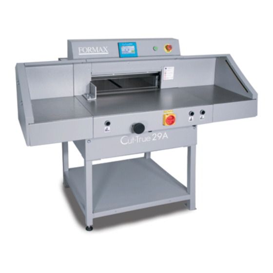
- Page 1 Cut-True 29A S/N 0592 and above Electric Guillotine Paper Cutter OPERATOR MANUAL Second Edition 1/2019...
-
Page 3: Table Of Contents
CONTENTS 1.GENERAL INFORMATION ....................6 1.1 Identification ........................6 1.2 Purpose of use ........................ 7 1.3 Documentation ........................ 7 1.4 Introduction ........................8 2. SAFE OPERATION ......................8 2.1 Symbols: meaning and application ................. 9 2.2 Employee qualifications ....................10 2.3 Requirements for the operator's workplace.............. - Page 5 7.2 Danger zones in the cutter .................... 37 7.3 Starting the cutter ......................37 7.3.1 Commissioning ....................... 37 7.3.2 Diagnostics of the safety curtain after switching on the power supply....38 7.3.3 Emergency stop of the cutter .................. 39 7.3.4 Starting the cutter after emergency stop ..............
-
Page 6: General Information
1. GENERAL INFORMATION This operator manual introduces the machine for the user and shows what for the machine was designed for to enable safe and comfortable work on the machine Inside the manual there are listed special safety requirements necessary to use the product ... -
Page 7: Purpose Of Use
After the machine purchase in is suggested to check the serial numbers of machine nameplate with purchase documents. A –Machine category (Paper cutter) B –Machine type (G52) C - Four digits serial no. D – Production year E – Voltage (V) / frequency (Hz) F –... -
Page 8: Introduction
exemplary, available at manufacturer region when the manual was created. It is allowed to use other materials with similar properties available at local market. The manual should be always stored near the machine The staff of user should be familiar with the manual before starting to operate the machine. -
Page 9: Symbols: Meaning And Application
Despite all precautions the operating of the machine by not trained staff or wrongly trained can cause the risk of damage. Each person present during the installation, maintenance and usage of the machine must be familiar with the manual, especially the chapter Safety of use. Despite the obligation to do it prior using the machine such means should be also repeated! Possible effects of incorrect usage: ... -
Page 10: Employee Qualifications
• Children must not operate the device! • Do not put hands underneath the knife! Do not leave knives unattended Do not remove or transport knives without covers! Risk of injury! • Do not cut hard materials or materials, which may be splattered 2.2 Employee qualifications ... -
Page 11: Requirements For The Operator's Workplace
INFO Before operating the cutter the operator must read the operating instructions. Every employee delegated to work during assembly, disassembly, reassembly, commissioning, servicing and maintenance (technical inspection, servicing, repairs) of the cutter must read the entire operating manual, in particular the chapter "Safety of use". -
Page 12: Expected Risks When Operating The Cutter
Ambient air temperature: + 5 ° C - + 30 ° C 2.4 Expected risks when operating the cutter Using the single cutter as intended, you can predict some of the risks to your life and health. To avoid existing hazards, the rules of using and operating the cutter must be explained in detail. -
Page 13: Description And Evaluation Of Residual Risk
Cutting zone Cut off, cut Manipulation with a knife during the change Cut off, cut The edges and corners of the cutter elements Chipping, clash Surfaces Electrical hazards Direct touch Electric shock Description and evaluation of residual risk The Grafmasz company takes responsibility for the construction of the cutter in order to eliminate the danger, although some risk elements during the cutting machine operation are possible. -
Page 14: Safety Systems Used In The Cutter
When following such recommendations as: • Comply with the safety rules described in the operating instructions • Careful reading of the operating instructions • It is forbidden to put your hands in dangerous and forbidden places • It is forbidden to make any alterations on your own •... - Page 15 Figure 3. Arrangement of covers and protective elements Table 3. Safety measures used to eliminate hazards (according to Figure 3) Identification Factors and / or dangerous places Security measures MECHANICAL fixed cover The lever assembly mechanism of the 1,3,4 clamp bar drive ...
- Page 16 - fixed cover - electro sensitive protective device Lowering of the clamp two-handed device Emergency stop fixed cover Backguage movement Emergency stop - two-handed device - electro sensitive protective device Cutting zone cam device that monitors the knife stop at the upper turning point...
-
Page 17: Safe Working Rules
- protection against indirect contact according to PN-EN Indirect touch 60204-1 - continuity of the protective conductor 2.8 Safe working rules 1. training of the operator: • aware of the potential hazards that may occur when operating the cutter • clearly defining activities which, under the conditions of a given plant, are or are not the responsibility of the cutter operator and are reserved for designated authorized persons, in particular as regards the removal of defects and repairs - including electrical installations. -
Page 18: Transport And Storage
eliminating production stoppages. INFO At the latest after 5 years of use, at least control of the folowwing functions should be carried out and the results should be documented. operation of the control function check the correct position of the knife ... - Page 19 Figure 4. Cutter in a transport crate. Figure 5a. Transporting the cutter in the crate using a forklift.
-
Page 20: Delivery Status
Figure 5b. Transporting cutters with a pallet truck 3.3 Delivery status The cutter can be supplied by the manufacturer: • completely assembled and ready for use (Fig. 6a). • with disassembled side tables, assembly of tables according to Figure 6b. •... - Page 21 Figure 6a. Cutter without side tables Figure 6b. Tightening of the side tables 1. Left side table + M8x25 screw (4 pieces) + washer 8 (4 pieces) 2. Right side table + M8x25 screw (4 pcs.) + 8 washer (4 pcs.) 3.
- Page 22 4. Right photocell + M8x25 screw (4 pcs.) + 8 washer (4 pcs.) + M8 nut (4 pcs.) Figure 6c. Assembling of the base 1. Right side 1 piece 2. Left side 1 piece 3. Bracket 1 item 4. Shelf 1 item 5.
- Page 23 Figure 6d. Assembled base Figure 6e Tightening the transport handles...
- Page 24 Figure 6f. Setting the cutter on the base 1. Transport handle 2 pcs 2. M12x30 screw 4 pcs 3. cutter 4. basis 5. M10x16 screw 4 pcs 4 strong people are needed to raise the machine and set it on the base! Danger! Protect the power cable from sharp tools, high temperature and oil.
-
Page 25: Setting The Cutter
3.4 Setting the cutter Figure 7. Adjusting the cutter setting. The slicer does not need to be attached to the ground. The correct and safe setting of the machine is achieved by twisting the adjusting foot 1, as shown in Figure 7. 3.5 Work area In order to easily access the cutter's mechanisms during adjustment, maintenance or servicing activities, it is recommended to keep a free space of about 0.5 m around the... -
Page 26: Technical Characteristics Of The Guillotine
Figure. 8 4. TECHNICAL CHARACTERISTICS OF THE GUILLOTINE 4.1 Destiny The cutter is intended for trimming the required size of a stack of paper, cardboard and other materials: plastics, fibers, metal foil, laminate, rubber, etc. It is mainly used in printing houses, bookbinding shops and offices. -
Page 27: Technical Data - Electrical System
Table PARAMETER G 52 Maximum stack width (mm) Without false clamp Maximum stack height (mm) With false clamp Cutting depth (mm) Front table lenght (mm) Without false clamp Narrow cut (mm) With false clamp Sound power level (dB) 74,6 Backguage speed (mm/s) Side table load (kg) Without side table Weight (kg) -
Page 28: External Dimensions
4.2.3 External dimensions The dimensions of cutters in different equipment versions are shown in figure 9a, 9b and table 6. Figure 9a. External dimensions of the cutter without side tables. - Page 29 Figure 9b. External dimensions of the cutter with side tables Table 6. DIMENSION VALUE(mm) 1244 1215 1430 1533...
-
Page 30: Operation
5. OPERATION 5.1 Operating safety 5.1.1 Safety instructions • Before each start-up or start-up on the cutter, the next change should be made to ensure that the safety components are complete and work properly. • The cutter can only be operated if all safety components and safeguards such as detachable covers, emergency stop switches are installed and fully functional. - Page 31 Figure 10. Elements of G 52 cutting machine operation and signaling 1. Main switch 2. Palm button, (emergency stop) 3. Button that activates the control system. 4. Buttons enabling the cutting cycle (two-hand cutting system) 5. A button that activates the movement of the clamp bar 6.
- Page 32 8. Safety curtain (non-contact protection device) 8a. Transmiter 8b. Receiver Figure 11. Indicators of the receiver The receiver is equipped with six LEDs informing about the operating status: Table 7. Item Color of the LED Display Text Red/green Status OSSD OSSD Error indication Blue...
- Page 33 Table 8. Blue LEDs informing about the quality of the settings LEDs informing about quality Diode LED OSSD Meaning settings The setting is insufficient or the protective field is interrupted at least It does not light up partially. The receiver can no LED synchronize with the transmitter.
-
Page 34: Electrical Apparatus
Figure 12. Indicators of the transmitter The transmitter is equipped with two LEDs informing about the operating status: Table 9. Position LED diode colour Indication Text Work status yellow indicator Error indication 5.3 Electrical apparatus Danger! Dangerous electrical voltage! Before opening the housing, switch off the main switch! - Page 35 1. Hinged housing of electrical apparatus (Fig. 13) 2. Nuts fixing the housing (Fig. 13) Figure 13. Location of electrical apparatus...
-
Page 36: Power Supply
6. POWER SUPPLY Figure 14. Location of the nameplate Data on the plate: - 230V power supply - 50 Hz frequency - 2 kW power - 20 A protection OSTRZEŻENIE WARNING The data on the plate must correspond to the current parameters in the mains! Parameters of frequency converters (inverters) are set by the cutter manufacturer and can not be changed! -
Page 37: Using The Cutter
7. USING THE CUTTER The user is obliged to create working conditions at the cutter workplace that preclude the operator from slipping or falling due to poor ground conditions, the way of routing the wires or the lack of convenient access! 7.1 Work area for operational staff The working area is the front side of the (operational) cutter! 7.2 Danger zones in the cutter... -
Page 38: Diagnostics Of The Safety Curtain After Switching On The Power Supply
1. Set the main switch 1 to "ON" 1 position (Fig. 15) 2. Press the green button 2 (Fig.15) - green LED 3 on the program unit 6 display lights up (fig.15) - the green OSSD 1 LED lights up (Fig.11) in the receiver 4 (Fig.15) Figure 16. -
Page 39: Emergency Stop Of The Cutter
In case of an error on the device, the red LED will light. On the side receiver red error LED - in combination with blue LEDs -indicates the cause of the error, Danger! In case of malfunction of photocells, immediately contact the service! 7.3.3 Emergency stop of the cutter 1. -
Page 40: Changing The Position Of The Backguage With The Handwheel
7.4.1 Changing the position of the backguage with the handwheel 1. Press knob 2 2. Turn the knob to bring the backguage closer or closer by reading the position value on the programmer screen. Figure 17. Arrangement of the positioning elements of backguage 7.5 Clamping the material Danger! not put your hands into the cutting area when pressing! -
Page 41: Clamping And Holding Of Sliced Material
7.5.2 Clamping and holding of sliced material. 1. Press simultaneously the left cutting button 1 and the pressure button 2 (fig.18) 2. Release the clamping button 2 - clamping will continue for the whole time you hold button 1 3. Release button 1 - the clamp will return to the upper position Figure 18. -
Page 42: Change Of Clamping Force
7.5.3 Change of clamping force Changes of the clamping force are made on the screen of the programmer 3 (Fig.18) The method of changing the clamping force has been described in the "Instructions for program unit". 7.5.4 Rules for selecting the contact pressure. The value of clamping force is selected experimentally, in relation to the type, width and height of the cut material. - Page 43 Fig. 19. Operating and signaling elements used during cutting. Cutting can be done if: 1. There is no object in the work area of the light barrier - the green OSSD 1 LED lights up (Fig.11) on the receiver 1 (Fig.19). 2.
-
Page 44: Operational Activities
8. OPERATIONAL ACTIVITIES 8.1 Replacing the knife in the cutter It is recommended, on the basis of experience, to change the knife after about 8 hours of effective, continuous work. Danger! Risk of injury! • Danger of injury to the operator and auxiliary personnel •... -
Page 45: Removing The Knife
8.1.1 Removing the knife Figure 20. 8.1.1.1 Select the "Change knife" function on the programmer 1 screen (Fig.20) ("Programmer's manual"). 8.1.1.2 Pressing the push buttons 2 (fig.20) at the same time, start the cutting cycle. The knife 3 is held in the lower position. 8.1.1.3. - Page 46 Figure.21 8.1.1.4 Remove the four screws 1 (fig.21) securing the cover 2 and remove cover 2. Figure.22 Unscrew and remove the first fastening screw 1 from the right side of the cutter bar (Fig. 22). 8.1.1.5 Switch on the power supply of the electrical system by turning the main switch knob 2 (fig.22) to position "I"...
- Page 47 8.1.1.7 On the program screen 4 (fig.22), deactivate the "knife change" function 8.1.1.8 Press simultaneously on the push buttons 5. The knife will return to its upper position. Figure 23. 8.1.1.9 Unscrew and remove the fastening screws 1 and 2 (Fig. 23). 8.1.1.10 In the place of removed screws 1 and 2 (fig.23), screw in the transport handle 1 (fig.24).
- Page 48 Figure 24. Figure 25.
- Page 49 Figure 26. Figure 27. 8.1.1.12 holding the transport handles release the clamp by turning them 1/2 turn at a time to the left (fig 26) and carefully pull the knife down (fig 27). Take the removed knife...
- Page 50 into the special protective packaging (Fig. 28a - 28d.) With the blade inwards and fasten it with two screws. To unscrew the bolts fixing the blade knife, use the RWTg 8 wrench provided on the cutter. Figure. 28a. Knife in the transport handle Figure 28b.
- Page 51 Figure 28 c. Unscrewing / securing the transport handles Figure 28d. Fixing the knife in the package 1. Packaging 2. Cover 3. Screw 4. Nut 5. Washer 6. Knife 7. Knife change holder...
-
Page 52: Inserting A Knife
8.1.2 Inserting a knife 8.1.2.1. Remove all adjusting screws 1 (figure 29) so that their faces are hidden in the knife bar body. Figure 29 B - the adjusting screw does not protrude below the protrusion 2 in the cutter bar - correct position. - Page 53 Figure 30. Insert the knife so high that its upper surface will rest against the protrusion in the knife bar 2 (Fig. 29). Figure 31.
- Page 54 8.1.2.4 Pre-attach the knife to the cutter bar by turning both transporting handles 1 to the right (fig. 31). 8.1.2.5 Install the fastening screws 2 (fig. 31). 8.1.2.6 Unscrew both transport lugs 1 (figure 31) and replace them with the mounting screws 1 and 2 (fig.
- Page 55 Figure 32a. 8.1.2.11. Screw in the bolt 2 lightly (fig.32a) Figure 33. 8.1.2.11.Remove (loosen) the fixing screws 4 (fig.33) so that the knife falls under its own weight on the base bar with its entire length. 8.1.2.12. Tighten the adjustment screws 5 (fig. 33) as far as they will go, so that the blade of the knife cuts into the base bar, approx.
- Page 56 8.1.2.13. Tighten the fixing screws 4 (figure 33) 8.1.2.14. Switch on the power supply of the electrical system by turning the main switch knob 3 (fig. 33) to position "I". 8.1.2.15. Turn off the "knife change" function on the programmer 1 (fig.33) 8.1.2.16.
-
Page 57: Reversing Or Replacing The Cutter Bar
8.2 Reversing or replacing the cutter bar Danger! Risk of injury! The cutting quality of the lower stack sheets and the dulling of the knife depend to a large extent on the cutting stick. Replacing or reversing the cutting stick is recommended after each knife change or in the event of not cutting the lower sheets OSTRZEŻENIE WARNING... -
Page 58: False Clamp
1. Cutting stick 1 2. Tables 2 3. Fixing pin 4. Screwdriver 8.2.1 Lift (lift) the cutting stick 1 with a screwdriver 4 (fig. 35) 8.2.2 Rotate or replace the cutting stick 8.2.3. Insert the replaced stick into the channel between the tables 2 and place it on the dowel 3 (Fig. - Page 59 Figure 37. False clamp plate (insert) The clamp bar insert (fig. 37) is attached under the front table in the place shown in figure 38. Figure 38. Placement of the insert before attachment in the pressure bar...
- Page 60 Danger! Risk of injury! In order to mount the insert in the pressure bar: 8.3.1 Pressing buttons 1 (fig. 39) cause the clamp bar 5 to move down. 8.3.2 When the pressure bar 5 lowers by approx. 2 cm, revealing the holes for the screws 4, release the right button 1 (left button 1 still pressed) 8.3.3 Press the 2 "O"...
-
Page 61: Adjusting The Parallelism Of Backguage
Figure 39. Operating elements used when mounting the insert into the pressure bar 8.4 Adjusting the parallelism of backguage Depending on the required inclination of backguage, its adjustment should be carried out using drawings 40 and 41,... - Page 62 Drawing. 40 Removing the cover To adjust backguage: 8.4.1 unscrew the screws 1 (fig.40) 8.4.2 remove the cover 2 (fig.40) 8.4.3 loosen the screws 1 (fig.41) 8.4.4 loosen the nuts 2 (fig.41) 8.4.5 by turning the screws 3, place the approaching backguage 4 (Fig. 41) at the right angle 8.4.6 lock the adjustment screws with 3 nuts 2 (fig.41) 8.4.7 firmly tighten the screws 1 (fig.41)
-
Page 63: Maintenance
Figure 41. Adjusting the backguage 9. MAINTENANCE Danger Maintenance and lubrication work should be carried out after turning off the machine (main switch in position "0") 9.1 Daily maintenance Every day, remove all waste from the cutter and the operator's working space. 9.2 Maintenance that should be performed regularly At regular intervals, waste and dirt should be removed from hard to reach machine and surrounding areas:... -
Page 64: Lubrication
• Air intakes for motors must be kept free of dust and debris. Danger Caution- fire hazard with insufficient ventilation. The machine guards must be put back into place immediately after maintenance work has been completed! 9.3 Lubrication The list of lubrication points is shown in Figures 44, 45, 46, 47, 48 and described in table 10. - Page 65 Figure 42. Removing the upper cover (2) and back (1) Figure 43. Removing the bottom cover (1)
- Page 66 Figure 44 Lubrication locations of the knife assembly. Figure 45. Lubrication points of the knife assembly (1), the clamp bar (2), the guide shaft of the feed mechanism (3)
- Page 67 Figure 46. Grease location of the lead screw. The worm gear mechanism is filled with an exchangeable oil. The exchange should be made after 5 years of work. The use of GL-5 and / or MIL-L-2105D gear oil is recommended. Figure 47.
-
Page 68: Oil Change In Gearboxes
Figure.48. Grease location of the pinion bearings 9.3.1 Oil change in gearboxes The worm gear reducers (Fig.49) and the pressure drive are filled with an exchangeable oil. The exchange should be made after 5 years of work. The use of GL-5 and / or MIL-L- 2105D gear oil is recommended. -
Page 69: Inspections
Figure 49. Oil change in the gear unit. Danger! Risk of injury! After lubrication: Using a cloth, completely remove any excess lubricant (grease, oil), in particular from the table surface on which the cutting material is laid and the work pieces in contact with the cut material, ie the knife body and the clamp bar. -
Page 70: Knife Regeneration
9.4.2 Knife regeneration The quality and accuracy of cutting depends primarily on the sharpness of the knife and the right angle of its blade. 9.4.2.1 Features of a blunt knife • rough and uneven surface of the cut ream • ticking the edge of the cut material •... -
Page 71: Basic Procedures For Removing Various Types Of Defects
10.2 Basic procedures for removing various types of defects Electrical faults: check the compatibility of the direction the motor is turning check the fuses in the machine measure the voltage check that all connectors are tightened securely ...
Need help?
Do you have a question about the Cut-True 29A and is the answer not in the manual?
Questions and answers