
Subscribe to Our Youtube Channel
Related Manuals for Alfa Laval Emmie


Summary of Contents for Alfa Laval Emmie
- Page 1 Alfa Laval Emmie Mobile oil cleaning system Instruction Manual Book No.: 9017434-02 Rev. 8 Product No.: 9016159-80, -81 9016160-80, -81...
- Page 2 Telephone: +46 8 530 650 00 Telefax: +46 8 530 310 40 © Alfa Laval Tumba AB 05-2016 Original instruction This publication or any part there of may not be reproduced or transmitted by any process or means without prior written permission of...
-
Page 3: Table Of Contents
Contents Safety instructions Application Machine plates Description of main parts System overview Hoses Separator Pump Starter/control unit Collecting tank Heater Working principle of the separator Introduction Clarifier operation Purifier operation Changing operation mode Control Cabinet Operator panel 6.1.1 Program 6.1.2 Changing of programs 6.1.3 Adjustable parameters... - Page 4 Start Operation Standby Stop How to drain hoses and heater Trouble shooting Cleaning system/separator does not start or stops shortly after start Pump does not start Pump stops Heater does not start Separator stops Noise Separator vibrates Insufficient separation result No flow from pump 8.10 Flow too low...
- Page 5 Every second year 9.3.1 Separator Dismantling - assembly instructions for separator 9.4.1 Introduction 9.4.2 Cleaning of bowl 9.4.3 Replacement of O-rings in purifier bowl 9.4.4 Replacement of O-rings in clarifier bowl 9.4.5 Replacement of motor bearings 10 Technical data 10.1 Technical data, system 10.2 Declaration...
-
Page 7: Safety Instructions
Ensure that personnel are competent and have sufficient knowledge of maintenance and operation. • Use only Alfa Laval genuine spare parts and the special tools supplied. Electrocution risk Switch off the power supply and remove the electric cables from the sockets before opening the... - Page 8 1 Safety instructions Disintegration hazard The separator is supplied with a safety yoke and a magnetic safety switch. Modifications to the machine which put the safety devices out of operation can lead to serious injury or damage. stop If excessive vibrations occur, the separator.
-
Page 9: Application
2 Application The Alfa Laval Emmie oil cleaning module is here included in the Alfa Laval Emmie oil cleaning system. The module can be bought separately and included in a similar system to the one described in this book. The Alfa Laval Emmie hydraulic oil cleaning... - Page 10 2 Application...
-
Page 11: Machine Plates
3 Machine plates The cleaning unit has two different machine plates. One for the separator only One for the complete unit G1105111 When ordering spare parts for the When ordering spare parts for the cleaning unit (except the separator) separator itself, please specify the please specify the article and serial type, product and serial numbers numbers stamped on the machine... - Page 12 H. Serial No.: D. Direction of rotation: Enclosure: E. Supply voltage: Article No. Serial No./Year Manufacturer Alfa Laval - Krakow Service enquiries www.alfalaval.com G1102721 Example of machine plate (complete unit) A. Article No. B. Serial No. C. Manufacturing Year Note that the illustrations are examples of a machine plates.
-
Page 13: Description Of Main Parts
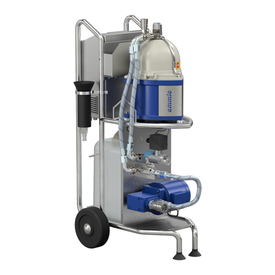
4 Description of main parts System overview The Alfa Laval Emmie unit consists of the following parts (numbered in process order): Parts marked with *) are further described on pages to 18. Coupling device fitted in oil tank Inlet hose (1/2”) from tank to pump Feed pump for the oil Hose (1/2”) from pump to heater... - Page 14 4 Description of main parts 13. Starter/control unit For starting, stopping and supervising the cleaning unit (except heater). The main part in the control unit is the PLC (Programmable Logic Computer) which supervises the starting and stopping of the cleaning unit. It also supervises system functions as:frequency converters, one for the separator and one for the pump.
- Page 15 4 Description of main parts G1105211...
-
Page 16: Hoses
4 Description of main parts Hoses The hose from the tank to the cleaning unit (cold side) is 1/2” and the hose from the cleaning unit back to the tank (warm side) is 3/8”. When the two coupling halves are fitted into each other, remember to secure the coupling by turning the locking ring until it engages. -
Page 17: Separator
4 Description of main parts Separator The separator has a bowl hood interlock (3) over the hood (2) and connection housing (1). A magnet (4) in contact with a safety switch indicates if the yoke is in correct position. If not, no power is supplied to the motor. -
Page 18: Collecting Tank
4 Description of main parts Collecting tank The tank stands on a support under the separator which is held in its upper position by a spring with adjustable tension. The spring can be adjusted by the handle (1) on the underside of the support. When the collecting tank is nearly full the weight will overcome the spring tension and a limit switch is actuated. -
Page 19: Working Principle Of The Separator
5 Working principle of the separator Introduction Separation takes place in a bowl (1), which rotates at high speed generating powerful centrifugal forces. The speed of the electric motor (6) driving the bowl spindle (3) is controlled by a frequency converter in the control cabinet. - Page 20 5 Working principle of the separator The separator can be operated either as a clarifier or as a purifier. clarifier operation Choose when or only traces water in the oil. At delivery the separator is assembled for clarifier operation. purifier operation Choose when the oil contains much water...
-
Page 21: Clarifier Operation
5 Working principle of the separator Clarifier operation The unseparated oil continuously enters at (A) and flows into the bowl (1). The particles (2) are separated and deposited on the bowl wall. The cleaned oil is forced inwards to the centre of the bowl and up to a paring disc (not illustrated). Since the oil is rotating, the stationary paring disc acts as a pump which forces the oil out through outlet (B) under a constant pressure. -
Page 22: Changing Operation Mode
5 Working principle of the separator Changing operation mode When changing operating mode from clarifier to purifier, or vice versa, proceed as follows: 1. Dismantle the separator in the same way as when cleaning the bowl, see 9.4.2 Cleaning of bowl on page 2. - Page 23 5 Working principle of the separator 5. Exchange one insert for the other. G1114311 G1114411 Clarifier bowl insert Purifier bowl insert 1. Bowl bottom (clarifier) 2. Bottom disc (purifier) 3. Bowl bottom (purifier) with three holes (*) 6. When fitting the insert, check that the cylindrical pin (1) in the shaft is not missing.
- Page 24 5 Working principle of the separator 7. Tighten the centre screw. Check that one washer is fitted under the screw. G05191c1 8. Fit the sleeve with wings, lower part of paring chamber, level ring and O-ring. 9.4.2 Cleaning of bowl See the instructions in fitting the level ring and O-ring correctly.
-
Page 25: Control Cabinet
6 Control Cabinet The operator panel is a 4" touch screen placed on top of the control cabinet. Do not use metal or any sharp objects to operate the panel. A stylus pen or similar however, can be used. Inside the control cabinet there are two frequency converters for regulating the speed of the separator and the pump, a 24VDC power supply and a PLC. - Page 26 6 Control Cabinet Control bar The control bar is always visible at the bottom of the screen. G1101211 Start, Stop and Standby buttons are blue when they are accessible, and grey when they are not. When an operating mode is active the corresponding button is circled in green.
- Page 27 6 Control Cabinet Tiles The startup screen contains three tiles, each representing a sub-equipment of the unit. When a sub-equipment is running the corresponding tile will be circled green. G1113811 Tapping a tile will display an overview of all devices within that sub-equipment. On the left hand side there is a status row for the sub-equipment and if applicable, setpoints for the devices and control functions for that subequipment.
- Page 28 6 Control Cabinet Separator The Separator screen shows the separator motor, the bowl hood interlock and the tank limit switch. A trip counter for batch running time is available. G1113831 Pressure control The Pressure control screen shows the pressure sensor and the pressure regulation valve. Pressure set-point can be changed from here.
- Page 29 From there the operator is given access to the following screens (starting on the top left hand side): Parameters Configuration of the system. Only possible to change values when logged in as Administrator. Administrator access level is only for Alfa Laval service engineers. Alarm history A list of all past alarms System time Set system time so correct time stamps are made in the alarm list.
- Page 30 6 Control Cabinet Alarm list The Alarm list shows all active and all unacknowledged alarms. It is always accessible from the Control bar. G1113861 Alarms can be for operator information only but in most cases it also forces the unit to another operating mode. See ‘‘6.4 Alarm table” on page 33.
-
Page 31: Program
6 Control Cabinet 6.1.1 Program The unit is programmed with predefined programs: Mode Oil viscosity P1 Auto ISO VG 15-22 P2 Auto ISO VG 32-46 P3 Auto ISO VG 68 P4 Auto ISO VG 100 P5 Auto ISO VG 150 P6 Manual In P1-5 the heater is started when the starting process is completed (separator start, pump... -
Page 32: Adjustable Parameters
6 Control Cabinet 6.1.3 Adjustable parameters In manual mode, P6, all parameters can be adjusted. In auto modes, P1-5, it is possible to adjust the counter pressure. Parameter Interval Comments Min. 55 kPa Too high counter pressure (recommended Counter pressure 60 –... -
Page 33: Alarm Table
Empty the tank and start the pump. Oil tank full A202 Frequency converter Check separator motor connection. Separator motor fault for separator. Check separator motor. Check control overload cables to Frequency converter. A300 (For Alfa Alarm only Laval Emmie with heater only) Heater overheat... - Page 34 6 Control Cabinet...
-
Page 35: Operating Instructions
7 Operating instructions Separation time It is recommended that the oil volume (V) in the T = (V x 5)/100 complete system, not only the tank volume, is separated at least five times. The separation T = Minimum running time capacity will normally be adjusted to about 100 V = Volume in complete system (in litres) litres per hour. - Page 36 7 Operating instructions Control of water content Stop the separator. Move the hose outlet (1) from the collecting tank to the filler cup (2) and drain the content (about 1 litre). Pour over the content to a glass bottle or similar to check the water content.
-
Page 37: Before Start
7 Operating instructions Bowl wall Before start 1. Make sure that the pump is fully primed. Connect the inlet tube to the pump with the suction pipe and pour oil into the pump as illustrated. 2. Connect the hoses as described in chapter Description of main parts. - Page 38 7 Operating instructions 5. When using the unit onboard a ship, first fasten it firmly with straps (A) or similar to fixing points. G1104611 Never separate an unfiltered system without a strainer G0912421 fitted to the pump inlet. In such a case, use the special Suction pipe (½”) with built-on strainer suction pipe with the built-on strainer.
- Page 39 7 Operating instructions 7. Make sure that the three hood screws (3) and the knob (1) are firmly tightened and that the bowl hood interlock (2) is in closed (vertical) position. G0908811...
-
Page 40: Start
7 Operating instructions Start 1. Connect the unit to the power supply. If the power supply is equipped with an ELCB (Earth Leakage Circuit Breaker) make sure that it is of industrial type that allows higher leakage current. The unit must be connected to an earthed outlet. Program P1 –... - Page 41 7 Operating instructions When the filler cup is empty, close the valve, remove the filler cup and fit the protective cap (1) onto the connection. The filler cup must be removed in order to avoid vibration. The feed pump starts automatically G0906211 When the separator has reached full speed the feed pump starts.
- Page 42 7 Operating instructions 4. Evacuate air from the heater. Press the valve until oil is leaking. G09787s1 5. When the oil starts to flow through the separator the counter pressure will increase and regulation starts. The counter pressure is increased to the latest set value ±10%.
- Page 43 7 Operating instructions If the pump starts to emit cavitation noise (e.g. when the oil is of high viscosity or cold) turn the screw anti-clockwise to increase the internal leakage, which will eliminate the cavitation. 8. The recommended separation temperature depends on the oil viscosity.
- Page 44 7 Operating instructions To check the actual flow, proceed as follows: When the oil temperature has reached the set point, check the throughput of the separated oil. 100 - 120 l/h is recommended. With this flow the enclosed filler cup will be filled within 35 - 40 seconds.
-
Page 45: Operation
7 Operating instructions Operation 1. Check the cleaning unit for correct operation (temperature, counter pressure and vibration). This is especially important the first time the cleaning unit is run after installation or dismantling and assembly. g1106311 Recommended counter pressure is 60 – 90 kPa 2. -
Page 46: Stop
7 Operating instructions Stop 1. The cleaning unit is stopped by tapping the Stop button, or if an alarm forces the system to stop. Feed pump and separator are turned off. Pressure regulating valve is opened. g1106211 After each stop of the cleaning unit, the separator bowl must be cleaned well. -
Page 47: How To Drain Hoses And Heater
7 Operating instructions How to drain hoses and heater It is possible to drain the heater and the hoses (not the hoses from pump to separator and from separator to tank) by switching them in following way: 1. Stop the unit. 2. - Page 48 7 Operating instructions...
-
Page 49: Trouble Shooting
8 Trouble shooting Cleaning system/separator does not start or stops shortly after start Possible cause Action No power supplied Check the mains switch, fuses and supply line Bowl hood interlock is not in correct position Position the interlock correctly Defective magnetic switch indicating the Check that the switch opens and closes when position of the bowl hood interlock interlock is moved up and down... -
Page 50: Heater Does Not Start
8 Trouble shooting Possible cause Action Voltage protection on frequency card trips Check the voltage. If unstable voltage, connect because of too low/high voltage or voltage a transformer. spikes Remedy - replace Defective motor/frequency converter Heater does not start Possible cause Action No power supplied Check the mains switch, fuses and supply line... -
Page 51: Separator Vibrates
8 Trouble shooting Separator vibrates Disintegration hazard STOP If excessive vibrations occur, the separator Possible cause Action Bowl out of balance due to: Dismantle and clean the separator bowl. Be • Insufficient or incorrect cleaning sure that the separator is assembled correctly. (sludge in disc stack) •... -
Page 52: Flow Too Low
8 Trouble shooting 8.10 Flow too low Possible cause Action Low feed flow Increase the flow. Check for correct counter pressure. Counter pressure at outlet too high Reduce the counter pressure with the regulating valve (60 - 90 kPa is recommended) Leakage caused by incorrect assembly •... -
Page 53: Some Liquid Escaping Through Drain Outlet To Collecting Tank
8 Trouble shooting 8.12 Some liquid escaping through drain outlet to collecting tank Possible cause Action • Reduce the counter pressure with Counter pressure at outlet too high the regulating valve (60 - 90 kPa is recommended) • Reduce the flow Clogged disc stack Clean the bowl and disc stack Dismantle and check the separator bowl. -
Page 54: Separation Temperature Too Low
8 Trouble shooting 8.16 Separation temperature too low Possible cause Action Throughput too high Reduce the flow 8.17 Heater trips Possible cause Action Thermoswitch TS tripped (located in heater Reset the thermoswitch control cabinet) 8.18 Oil leaks from heater Possible cause Action Oil leaking from heater Remove the cover and tighten the four screws... -
Page 55: Maintenance
9 Maintenance Entrapment hazard Switch off the power supply, remove the electric cables from the sockets and make sure that rotating parts complete standstill have come to a before starting any dismantling work. Never use cleaning agents with a pH below 6 or above 9 as they can damage the metal surfaces. -
Page 56: Strainer
9 Maintenance Control of sludge content Dismantle the separator and measure the thickness (A) of the sludge collected on the bowl wall. The thickness should never exceed 10 mm. If the interval between bowl cleaning is too long, this can result in a sludge cake that is hard and difficult to remove. -
Page 57: Every Second Year
9 Maintenance Fit new vibration dampers. To get access to the dampers, only remove the three screws and washers shown in illustration 10 on page 66. Inspect the stop flanges of the dampers for possible damage and replace the stop flanges with new ones if necessary. Use Loctite 243 at assembly, see illustration 33 in chapter 9.4.5 Replacement of motor bearings. -
Page 58: Cleaning Of Bowl
9 Maintenance 9.4.2 Cleaning of bowl Comments to illustrations following. Illustration 4: Before dismantling the separator, wait until the rotating parts have come to a complete standstill, which will take up to two minutes. To be sure, open the front cover and check that the rotation of the electric motor shaft has stopped. - Page 59 9 Maintenance Dismantling G04491c1 *See comments on opposite page...
- Page 60 9 Maintenance Comments to illustrations on opposite page. Illustration 16: When fitting the bowl shell, press firmly downwards with both hands to overcome the resistance from the O-ring fitted on the bowl bottom. A “clicking” sound will be heard. G0912141 Illustration 17: If the level ring (1) and O-ring (2) have been removed, first fit the level ring and then the O-ring...
- Page 61 9 Maintenance Illustration 22: before Always screw home the knob fitted on the connecting housing tightening the screws shown in illustration 23. Otherwise there is a risk that the pin inside the connecting housing could break. Assembly <0.5 mm G0449281 *See comments above and on opposite page.
-
Page 62: Replacement Of O-Rings In Purifier Bowl
9 Maintenance 9.4.3 Replacement of O-rings in purifier bowl Converting from purifier to clarifier bowl or vice versa is described in 5 Working principle of the separator. Comments to illustrations on opposite page. Illustration 5: Take care of the washer. Illustration 14: Check that the washer is fitted. - Page 63 9 Maintenance First dismantle the separator bowl as described in 9.4.2 Cleaning of bowl on page G05191k1 *See comments on opposite page.
-
Page 64: Replacement Of O-Rings In Clarifier Bowl
9 Maintenance 9.4.4 Replacement of O-rings in clarifier bowl Converting from purifier to clarifier bowl or vice versa is described in 5 Working principle of the separator. Comments to illustrations on opposite page. Illustration 5: Take care of the washer. Illustration 14: Check that the washer is fitted. - Page 65 9 Maintenance First dismantle the separator bowl as described in 9.4.2 Cleaning of bowl on page G05191L1 *See comments on opposite page.
-
Page 66: Replacement Of Motor Bearings
9 Maintenance 9.4.5 Replacement of motor bearings First dismantle the separator bowl as described in 9.4.2 Cleaning of bowl on page G0449461... - Page 67 9 Maintenance G0449671...
- Page 68 9 Maintenance G0449681...
-
Page 69: Technical Data
10 Technical data 10.1 Technical data, system Type designation: Alfa Laval Emmie – mobile oil cleaning system Application: Cleaning of hydraulic oils Intended for land installations. Use is restricted to removal of solids and water from oils with the following specifications: Process media: Max. -
Page 70: Declaration
The technical construction file for the machinery is compiled and retained by the authorized person Hans Thomasson within the Product Centre for High Speed Separator sytems, Alfa Laval Tumba AB, SE-14780 Tumba Sweden. Signed for and on behalf of: ...................... -
Page 71: Installation
11 Installation 11.1 Installation alternatives The Alfa Laval Emmie cleaning unit can be connected to a hydraulic oil tank in the three ways described below. The third alternative normally needs no preparations for using the cleaning unit (except maybe removing a cover). However, for the two other alternatives the hydraulic oil tanks must be prepared as described below. -
Page 72: Connection To Drain Hole In Tank
11 Installation 11.1.2 Connection to drain hole in tank The suction hose is connected to an outlet fitted into the tank drain hole, while the return hose is connected to a hole on the opposite side of the tank. A shut-off valve must be connected between the tank and the quickcoupling for the outlet. -
Page 73: Lifting Instruction
12 Lifting instruction 12.1 Cleaning unit Attach two lifting straps (1) to the lifting hooks. The distance between the lifting hooks and crane hook should be min. 1 metre (A). Weight of unit is approx. 100 kg. Entrapment hazard Only attach the lifting straps to the two lifting hooks when lifting the cleaning unit. - Page 74 12 Lifting instruction...
-
Page 75: Diagrams
13 Diagrams 13.1 Electrical system Alfa Laval ref. 9014734 Rev. 7... - Page 76 Alfa Laval Tumba AB C:\Documents and Settings\SETUGNH\My Documents\My Pictures\alfalaval.bmp Company / customer Project description Emmie w. heater Main supply 230V AC (100/110/120VAC with optional transformer) Control voltage 24V DC Manufacturer (company) Alfa Laval Tumba AB Drawing number 9014734 Created on...
- Page 77 Created by Revised by Project Title Location Page Revision Revised date Page 2014-04-02 SETUTBL SETUTBL 2015-03-26 Emmie w. heater Cable-connection diagram 1 W001 W002 W003 W101 Department Approved date Approved by Mounting Latest Revision Document No. Next page 9014734 2015-10-23...
- Page 78 Created by Revised by Project Title Location Page Revision Revised date Page 2014-04-02 SETUAKL SETUAKL 2015-10-07 Emmie w. heater Cable-connection diagram W201 W202 W203 W401 Department Approved date Approved by Mounting Latest Revision Document No. Next page 9014734 2015-10-23 SETUNLN...
- Page 79 Created date Created by Revised by Project Title Location Page Revision Revised date Page 2014-04-02 SETUTBL SETUTBL 2015-03-26 Emmie w. heater Cable-connection diagram W402 W403 Department Approved date Approved by Mounting Latest Revision Document No. Next page 9014734 2015-10-23 SETUNLN...
- Page 80 Note: All signal cables should be a Signal Shielded Cable with the shield properly connected to earth as shown in the electrical drawings. 1) Cable not included in Alfa Laval delivery 2) Cable type and size according to VFD/motor specification For power cables, armour must be connected to the earth bar.
- Page 81 Created date Created by Revised by Project Title Location Page Revision Revised date Page 2014-04-02 SETUTBL SETUTBL =9014734 2014-09-05 Emmie w. heater Wiring table Department Approved date Approved by Mounting Latest Revision Document No. Next page 9014734 2015-10-23 SETUNLN +CP01...
- Page 82 Created date Created by Revised by Project Title Location Page Revision Revised date Page 2014-04-02 SETUTBL SETUAKL =9014734 2015-10-23 Emmie w. heater Control cabinet assembly Department Approved date Approved by Mounting Latest Revision Document No. Next page 9014734 2015-10-23 SETUNLN +CP01...
- Page 83 Created date Created by Revised by Project Title Location Page Revision Revised date Page 2014-04-02 SETUTBL SETUTBL =9014734 2015-03-24 Emmie w. heater Control cabinet assembly Department Approved date Approved by Mounting Latest Revision Document No. Next page 9014734 2015-10-23 SETUNLN +CP01...
- Page 84 Created date Created by Revised by Project Title Location Page Revision Revised date Page 2014-04-02 SETUTBL SETUTBL =9014734 2014-09-05 Emmie w. heater Control cabinet assembly Department Approved date Approved by Mounting Latest Revision Document No. Next page 9014734 2015-10-23 SETUNLN +CP01...
- Page 85 Created date Created by Revised by Project Title Location Page Revision Revised date Page 2014-04-02 SETUTBL SETUTBL =9014734 2015-03-24 Emmie w. heater Terminal assembly Department Approved date Approved by Mounting Latest Revision Document No. Next page 9014734 2015-10-23 SETUNLN +CP01...
- Page 86 Created date Created by Revised by Project Title Location Page Revision Revised date Page 2014-04-02 SETUTBL SETUTBL =9014734 2015-01-14 Emmie w. heater PLC Assembly Department Approved date Approved by Mounting Latest Revision Document No. Next page 9014734 2015-10-23 SETUNLN +CP01...
- Page 87 Created date Created by Revised by Project Title Location Page Revision Revised date Page 2014-04-02 SETUTBL SETUAKL =9014734 2015-10-22 Emmie w. heater 230VAC 24VDC Department Approved date Approved by Mounting Latest Revision Document No. Next page 9014734 2015-10-23 SETUNLN +CP01...
- Page 88 Separator Created date Created by Revised by Project Title Location Page Revision Revised date Page 2014-04-02 SETUTBL SETUTBL =9014734 2015-03-24 Emmie w. heater Separator Department Approved date Approved by Mounting Latest Revision Document No. Next page 9014734 2015-10-23 SETUNLN +CP01...
- Page 89 Pump Created date Created by Revised by Project Title Location Page Revision Revised date Page 2014-04-02 SETUTBL SETUTBL =9014734 2015-03-24 Emmie w. heater Pump Department Approved date Approved by Mounting Latest Revision Document No. Next page 9014734 2015-10-23 SETUNLN +CP01...
- Page 90 Overheat Created date Created by Revised by Project Title Location Page Revision Revised date Page 2014-04-02 SETUTBL SETUTBL =9014734 2015-03-26 Emmie w. heater Heater Department Approved date Approved by Mounting Latest Revision Document No. Next page 9014734 2015-10-23 SETUNLN +CP01...
- Page 91 Created date Created by Revised by Project Title Location Page Revision Revised date Page 2014-04-02 SETUTBL SETUTBL =9014734 2015-03-24 Emmie w. heater HMI Panels Department Approved date Approved by Mounting Latest Revision Document No. Next page 9014734 2015-10-23 SETUNLN +CP01...
- Page 92 Created date Created by Revised by Project Title Location Page Revision Revised date Page 2014-04-02 SETUTBL SETUTBL =9014734 2014-09-05 Emmie w. heater A1 - CPU Department Approved date Approved by Mounting Latest Revision Document No. Next page 9014734 2015-10-23 SETUNLN +CP01...
- Page 93 Created date Created by Revised by Project Title Location Page Revision Revised date Page 2014-04-02 SETUTBL SETUTBL =9014734 2015-03-26 Emmie w. heater X1 - Inputs Department Approved date Approved by Mounting Latest Revision Document No. Next page 9014734 2015-10-23 SETUNLN +CP01...
- Page 94 Created date Created by Revised by Project Title Location Page Revision Revised date Page 2014-04-02 SETUTBL SETUAKL =9014734 2015-10-07 Emmie w. heater X2 - Inputs Department Approved date Approved by Mounting Latest Revision Document No. Next page 9014734 2015-10-23 SETUNLN +CP01...
- Page 95 Created date Created by Revised by Project Title Location Page Revision Revised date Page 2014-04-02 SETUTBL SETUTBL =9014734 2015-03-24 Emmie w. heater X3 - Outputs Department Approved date Approved by Mounting Latest Revision Document No. Next page 9014734 2015-10-23 SETUNLN +CP01...
- Page 96 Created by Revised by Project Title Location Page Revision Revised date Page 2014-04-02 SETUTBL SETUTBL =9014734 2015-03-26 Emmie w. heater A2 - Analog outputs Department Approved date Approved by Mounting Latest Revision Document No. Next page 9014734 2015-10-23 SETUNLN +CP01...
Need help?
Do you have a question about the Emmie and is the answer not in the manual?
Questions and answers