Table of Contents

Subscribe to Our Youtube Channel
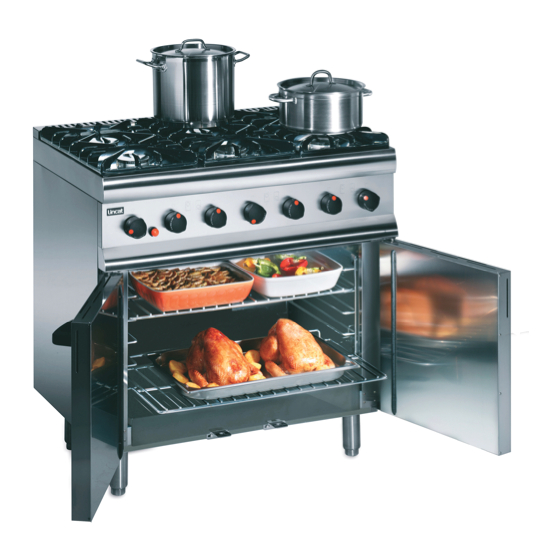
Related Manuals for First Choice Lincat Silverlink 600 SLR6


Summary of Contents for First Choice Lincat Silverlink 600 SLR6
- Page 1 SPARE PARTS DIAGRAM FOR Gas Oven Range Silverlink 600 Range First Choice Group Blakeney Way, Kingswood Lakeside Cannock, Staffs, WS11 8LD TEL: 01543 577778 FAX: 01543504141 Email: enquires@firstchoice-cs.co.uk Web: www.firstchoice-cs.co.uk...
- Page 2 Installation, Operating, Servicing and Conversion Instructions Silverlink 600 Gas Ranges SLR6, SLR6C, SLR9 and SLR9C Please make a note of your product details for future use: Date Purchased:_________________________ Model Number:__________________________ Serial Number:__________________________ Dealer:_________________________________ _______________________________________ IS 514 ECN 3706 Page 1 of 20...
-
Page 3: Table Of Contents
CONTENTS Important Information Warnings and Precautions Technical Data Checklist of Enclosures Installation and Commissioning Operating Instructions Cleaning Servicing, Maintenance and Component Replacement Conversion Fault Finding Spare Parts List Accessories Service Information and Guarantee IMPORTANT INFORMATION Read these instructions carefully before using this product, paying particular attention to all sections that carry warning symbols, caution symbols and notices. -
Page 4: Warnings And Precautions
WARNINGS AND PRECAUTIONS This appliance must be installed, commissioned, serviced and converted by a qualified person in accordance with national and local regulations in force in the country of installation. Strip plastic coating and clean the appliance before use. During operation parts may become hot - avoid accidental contact. Parts protected by the manufacturer shall not be adjusted by the user. -
Page 5: Technical Data
TECHNICAL DATA Model SLR6 SLR9 Dimensions Overall height (mm) 925 to hob 960 to pan support Width (mm) Depth (mm) Weight (kg) 69kg (Net) 85kg (Net) Hob cooking surface w x d (mm) 590 x 500 890 x 500 Usable oven capacity w x d x h (mm) 425 x 345 x 400 660 x 345 x 400 Oven shelf size (mm) -
Page 6: Checklist Of Enclosures
CHECK LIST OF ENCLOSURES Model SLR6 SLR9 Tick Warranty Card Pan Supports User Instructions IS 514 ECN 3706 Page 5 of 20... -
Page 7: Installation And Commissioning
INSTALLATION AND COMMISSIONING Site this appliance beneath an extraction canopy for the removal of combustion products. Installation must include sufficient ventilation to prevent the occurrence of unacceptable concentrations of substances harmful to health in the room of installation. There must be a minimum free area of 4.5cm per kW of total heat input. -
Page 8: Operating Instructions
OPERATING INSTRUCTIONS Only qualified or trained personnel should use this appliance. LIGHTING SEQUENCE Please ensure that the gas isolation valve for the appliance is turned to the open position before attempting to light this unit. Hob Burners From the OFF position: press and turn the control knob anti-clockwise to any position between the two stylized flames to allow gas through to the burner. - Page 9 Oven Temperatures The temperatures on the thermostat knob are a guide and generally reflect the NOTE temperature at the centre of the oven. The temperatures in the oven will vary from top to bottom. It may be necessary to periodically rotate product being cooked to ensure even cooking.
-
Page 10: Cleaning
CLEANING Do not use a water jet or steam cleaner, and do not immerse this appliance. Clean all panels with warm water and mild detergent, do not use abrasive materials. Dry with a soft cloth. It is important that users of the appliance systematically check and clean down as necessary areas of the hob and oven cavity that have accumulated oils, fats and other combustible debris from previous cooking. -
Page 11: Servicing, Maintenance And Component Replacement
SERVICING, MAINTENANCE AND COMPONENT REPLACEMENT The replacement of serviceable parts can only be carried out by registered authorised personnel and must and must be in possession of up to date licensing. FASCIA PANEL REMOVAL Care should be taken when removing the fascia panel as the oven ignitor lead will be attached to the ignitor. - Page 12 Hob Burner Components Isolate the gas supply to the appliance To replace the burner and its parts: BU09 Remove the burner cap 'BU09' BU08 Remove the burner head 'BU08' Remove the 3 screws 'FAS601 Remove the control knobs from the valves Remove the fascia panel FAS601 Loosen the burner feed pipe connection...
- Page 13 Oven Burner Components Ignitor Electrode To remove the ignitor (IG16) electrode remove the lead from the electrode Remove the retaining screw FAS360 and nut FAS016 Replace the ignitor, secure and refit the lead Thermocouple Loosen the lock nut at the tip side of the thermocouple (TC33) and withdraw from the burner bracket Remover the control knobs and fascia panel Loosen the thermocouple nut at the thermostat...
- Page 14 Thermocouple Setting To correctly position the thermocouple the lock nuts will require setting on the barrel of the thermocouple body Feed the replaced thermocouple as detailed above Position the thermocouple as detailed below and to the dimension given Lock the thermocouple into place Light the oven burner and set the thermostat to approximately 190 Allow the oven to reach temperature with the doors shut and turn the thermostat to the lowest setting (1301...
- Page 15 Thermostat Replacement Isolate the gas supply to the appliance To replace the thermostat remove the control knobs and fascia panel Supporting the thermostat body and loosen the thermostat feed nut TH17C Loosen the clamp screw FAS150 and lock nut FAS033 sufficiently to free the thermostat brackets TH17k and TH17L Free the thermostat TH17A from the manifold Maxx Free the thermocouple TC33 from the thermostat body...
-
Page 16: Conversion
CONVERSION Hob Burner Injector Changes Inlet Model Mark Part Number ∅ ∅ ∅ ∅ Pressure 20mbar 1.64 JE155 28-30mbar 0.98 JE157 37mbar 1.10 JE156 Oven Burner Injector Changes Inlet Model Mark Part Number ∅ ∅ ∅ ∅ Pressure 20mbar 1.90 JE107 SLR6 28-30mbar... - Page 17 Oven Burner To replace the oven burner injector Loosen the nut on the feed elbow CO133 Free the elbow and injector from the burner BUxx Free the injector JExx from the elbow Replace the injector applicable to the gas type with the washer WA13 and tighten against the elbow Refit the injector assembly to the burner Reconnect the elbow nut...
-
Page 18: Fault Finding
FAULT FINDING • Piezo oven ignitor not sparking Check for a Short in High Tension Lead Lead Detached Replace Lead Reconnect Lead Check Electrode for Fracture Replace Electrode Replace Piezo Ignitor • Burner/s will not light or stay lit Is There Gas at the Burner? Check Injector for Blockages Are Thermocouple Connections Loose? Tighten Connections... -
Page 19: Spare Parts List
SPARE PARTS LIST Description Part number Hob burner body BU07 Hob Burner head BU08 Hob burner cap BU09 Door bush BU55 Oven burner – SLR9 BU78 Oven burner – SLR6 BU86 Fixed castor CA86 Adjustable leg FE29 Piezo ignitor IG12 Ignitor electrode IG16 Ignitor lead... -
Page 20: Accessories
ACCESSORIES Part Number Description Used on IS 514 ECN 3706 Page 19 of 20... -
Page 21: Service Information And Guarantee
SERVICE INFORMATION For help with the installation, maintenance and use of your Lincat equipment, please contact our service department: 01522 875520 For non-UK customers, please contact your local Lincat dealer All service work, other than routine cleaning should be carried out by one of our authorised service agents.
Need help?
Do you have a question about the Lincat Silverlink 600 SLR6 and is the answer not in the manual?
Questions and answers