Subscribe to Our Youtube Channel
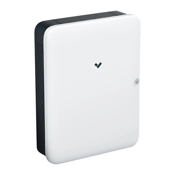
Summary of Contents for Verkada BP41
- Page 1 Install Guide BP41 Alarm Panel Verkada Inc. 405 E 4th Ave, San Mateo, CA 94401 All specifications are subject to change without notice sales@verkada.com Copyright © Verkada Inc. All rights reserved.
- Page 2 5/32 inch (4mm) drill bit for pilot holes ● A Cat5 or Cat6 Ethernet cable ● Connect After connecting BP41 to Ethernet and an AC outlet, visit www.verkada.com/start Verkada Inc. 405 E 4th Ave, San Mateo, CA 94401 All specifications are subject to change without notice sales@verkada.com...
- Page 3 Alarm panel is managing inputs and outputs, but cannot reach the server. Solid Blue Alarm panel is managing inputs and outputs. Verkada Inc. 405 E 4th Ave, San Mateo, CA 94401 All specifications are subject to change without notice sales@verkada.com...
- Page 4 Once the security screws are fully removed, slide the wall mount down and away from the main enclosure. Verkada Inc. 405 E 4th Ave, San Mateo, CA 94401 All specifications are subject to change without notice sales@verkada.com Copyright © Verkada Inc. All rights reserved.
- Page 5 Fasten the two security torx screws to and onto the mounting plate tabs. secure the enclosure to the mounting plate. Verkada Inc. 405 E 4th Ave, San Mateo, CA 94401 All specifications are subject to change without notice sales@verkada.com Copyright © Verkada Inc. All rights reserved.
- Page 6 End-of-Line Resistor (EOLR) Supervision EOLR supervision of inputs is optional on the BP41, and resistors do not need to be installed for normal operation. The panel does support single EOLR and double EOLR supervision modes. The supervision mode for each input can be configured in Command.
-
Page 7: Wiring Diagram
AUX outputs must not exceed 2A. alarm signaling device can be used with either output. Verkada Inc. 405 E 4th Ave, San Mateo, CA 94401 All specifications are subject to change without notice sales@verkada.com Copyright © Verkada Inc. All rights reserved. - Page 8 BP41s by Ethernet. Connect the BP41 power supply into your standard power outlet (120 VAC). Verkada Inc. 405 E 4th Ave, San Mateo, CA 94401 All specifications are subject to change without notice sales@verkada.com Copyright © Verkada Inc. All rights reserved.
- Page 9 être conservé aussi loin que possible du corps de l’utilisateur ou que le dispositif est réglé sur la puissance de sortie la plus faible si une telle fonction est disponible. Verkada Inc. 405 E 4th Ave, San Mateo, CA 94401 All specifications are subject to change without notice sales@verkada.com...
- Page 10 Appendix Support Thank you for purchasing this Verkada product. If for any reason things don’t work right, or you need assistance, please contact us immediately. verkada.com/support Sincerely, The Verkada Team Verkada Inc. 405 E 4th Ave, San Mateo, CA 94401 All specifications are subject to change without notice sales@verkada.com...


Need help?
Do you have a question about the BP41 and is the answer not in the manual?
Questions and answers