Table of Contents
Advertisement
Quick Links
BP41 LED Behavior & Details
Solid Orange
Controller is on and booting up.
Solid Blue
Controller is managing inputs
and outputs.
RS-485
Inputs 1-16
Status
LED
AC Power
LED
Battery
LED
12V Outputs A & B
Dual USB 2.0
Dual Ethernet
Federal Communication Commission Interference Statement
This device complies with Part 15 of the FCC Rules. Operation is subject to the following two conditions: (1) This device
may not cause harmful interference, and (2) this device must accept any interference received, including interference
that may cause undesired operation.
This equipment has been tested and found to comply with the limits for a Class B digital device, pursuant to Part
Flashing Orange
15 of the FCC Rules. These limits are designed to provide reasonable protection against harmful interference in a
residential installation. This equipment generates, uses and can radiate radio frequency energy and, if not installed
Controller is updating firmware.
and used in accordance with the instructions, may cause harmful interference to radio communications. However,
there is no guarantee that interference will not occur in a particular installation. If this equipment does cause harmful
interference to radio or television reception, which can be determined by turning the equipment off and on, the user is
Flashing Blue
encouraged to try to correct the interference by one of the following measures:
• Reorient or relocate the receiving antenna.
Controller is managing inputs
• Increase the separation between the equipment and receiver.
and outputs, but cannot reach
• Connect the equipment into an outlet on a circuit different from that
to which the receiver is connected.
the server.
• Consult the dealer or an experienced radio/TV technician for help.
FCC Caution: Any changes or modifications not expressly approved by the party responsible for compliance could
void the user's authority to operate this equipment.
This transmitter must not be co-located or operating in conjunction with any other antenna or transmitter.
Radiation Exposure Statement:
The product comply with the FCC portable RF exposure limit set forth for an uncontrolled environment and are safe
for intended operation as described in this manual. The further RF exposure reduction can be achieved if the product
can be kept as far as possible from the user body or set the device to lower output power if such function is available.
Industry Canada statement
This device complies with ISED's licence-exempt RSSs. Operation is subject to the following two conditions: (1) This
device may not cause harmful interference, and (2) this device must accept any interference received, including
interference that may cause undesired operation.
Le présent appareil est conforme aux CNR d' ISED applicables aux appareils radio exempts de licence. L'exploitation
est autorisée aux deux conditions suivantes : (1) le dispositif ne doit pas produire de brouillage préjudiciable, et (2) ce
dispositif doit accepter tout brouillage reçu, y compris un brouillage susceptible de provoquer un fonctionnement
indésirable.
Radiation Exposure Statement:
The product comply with the Canada portable RF exposure limit set forth for an uncontrolled environment and are
safe for intended operation as described in this manual. The further RF exposure reduction can be achieved if the
product can be kept as far as possible from the user body or set the device to lower output power if such function is
available.
Inputs 17-32
Déclaration d'exposition aux radiations:
Le produit est conforme aux limites d'exposition pour les appareils portables RF pour les Etats-Unis et le Canada
établies pour un environnement non contrôlé.
Le produit est sûr pour un fonctionnement tel que décrit dans ce manuel. La réduction aux expositions RF peut être
augmentée si l'appareil peut être conservé aussi loin que possible du corps de l'utilisateur ou que le dispositif est réglé
sur la puissance de sortie la plus faible si une telle fonction est disponible.
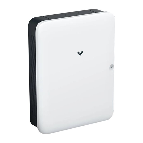
BP41 Overview
12V AUX
Door security screw
12V AUX
12V AUX
Wall mount
AC power
security screws
Power cable exit
Alarm panel
wiring exit
Wall mount
Door contact
switch
Power cable exit
Alarm panel
wiring exit
BP41 Alarm Panel
What's in the box
1 BP41 Alarm Panel
1 Wall mount plate
1 T10 Security torx screwdriver
1 Flat head screwdriver
12 Cable zip ties
4 Mounting screws and wall anchors
32 1kΩ EOL resistors
1 AC Power cable
What you'll need
• A working wired Internet connection over Ethernet
• A smartphone or laptop
• A #2 Phillips screwdriver or power drill with a #2 Phillips driver bit
• 5/16 inch (7.9mm) drill bit for wall anchors
• 5/32 inch (4mm) drill bit for pilot holes
• A Cat5 or Cat6 Ethernet cable
Advertisement
Table of Contents

Subscribe to Our Youtube Channel
Related Manuals for Verkada BP41


Summary of Contents for Verkada BP41
- Page 1 BP41 LED Behavior & Details Federal Communication Commission Interference Statement This device complies with Part 15 of the FCC Rules. Operation is subject to the following two conditions: (1) This device may not cause harmful interference, and (2) this device must accept any interference received, including interference that may cause undesired operation.
- Page 2 End-of-Line Resistor (EOLR) Supervision EOLR supervision of inputs is optional on the BP41, and resistors do not need to be installed for normal operation. The panel does support single EOLR and double EOLR supervision modes. The supervision mode for each input can be configured in Command.
Need help?
Do you have a question about the BP41 and is the answer not in the manual?
Questions and answers